Installing English Firmware on a FAST FWR171

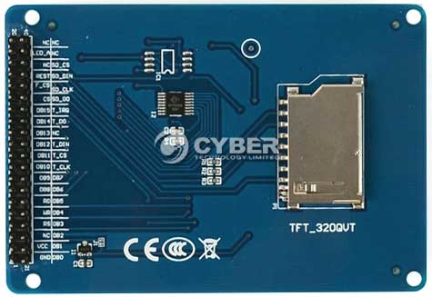
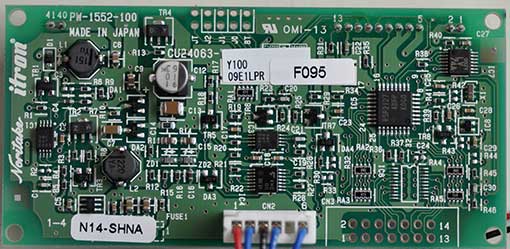
I recently learned that the FAST FWR171-3G is a lower cost clone of the TP-Link TL-WR703N, the only difference being the case. While browsing AliExpress, I found what I thought was a great deal… the FAST FWR171 for only $16. After waiting over a month to receive it, I noticed that it doesn’t have a USB port. Sheesh! I’m such an idiot. Just like when I mistakenly ordered a TL-WR702N from Amazon, it turns out that the FAST FWR171 is a clone of the TL-WR702N, not the TL-WR703N. AAARRGGGH!!! The trailing -3G in the FWR171-3G model number denotes the TL-WR703N clone!! So, not only did I end up with a router that’s useless for hacking, because it doesn’t have a enough RAM to load OpenWrt, has no USB port, and the firmware is in Chinese! FWR171_2 
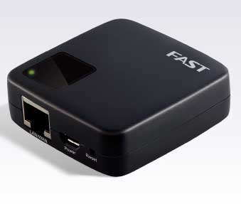
Notice the lack of a USB port in the photo of the FWR171 above. That alone should have warned me that I was ordering the wrong model. The FWR171-3G is slightly larger, and has a USB port on the side. Not wanting to be left with a completely useless device, I started browsing around for an English version of the firmware. None exists, but I found one for the TL-WR702N. Unfortunately, the web admin interface of the FWR171 checks the firmware for the correct device, and it won’t allow you to load a firmware for th TL-WR702N. Luckily, an OpenWrt forum member named jvvh5897 figured out how fool the firmware loader into thinking that it’s loading the appropriate firmware for a different model. In this thread, he describes how to modify an English TL-WR702N firmware to run on the Chinese model. I took that information, and used it to modify the English TL-WR702N firmware to run on the FW171. To adapt the TL-WR702N firmware to be accepted by the FWR171, we need to change two fields: 1) the system identifier and 2) the MD5 checksum of the firmware. In the TL-WR702N English firmware that I downloaded, the bytes in the blue box are the system identifier, and the bytes in the red boxes are the 16-byte MD5 checksum. 702fw 
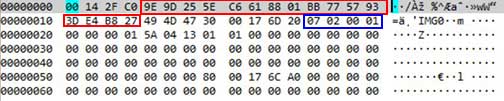
Note that the system ID contains 0702 for the TL-WR702N. I downloaded a firmware for the FWR171 and found that the system ID was 01 71 02 01. To update the MD5 sum, you must calculate the MD5 sum of the entire file, with the dummy MD5 sum CC 96 28 EE 8D FB 21 BB 3D EF 6C B5 9F 77 4C 7C inserted. Here is what the file looked like after I prepared it for calculating the MD5 sum: 151fwdummy 
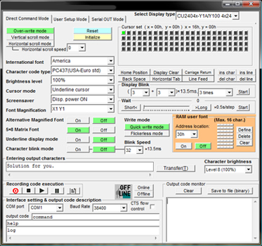
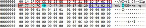
Next, I calculated the MD5 sum of the English TL-WR702N firmware file modified as above, and it was 06 7e a9 aa 7d 1e 75 10 b0 09 84 19 f1 d9 93 2d, so I replaced the dummy MD5 sum with those bytes and saved the file. Amazingly, the FW171’s firmware upgrader accepted it! To skip the hassle of modifying the firmware yourself, you can download my pre-hacked English TL-WR702N for FW171 firmware file. Using google, I found several descriptions of how to load the new firmware file into the FW171, but they were all wrong, because mine had the newer firmware, which checks for the proper system ID. To get to the web interface, set the IP number of your host computer’s Ethernet adapter to 192.168.1.3. Plug the FW171 into your host computer’s Ethernet port, and point a web browser to 192.168.1.253. Below is the firmware page for mine, which happened to be the latest firmware posted on www.fastcom.com.cn: fwver-sm 
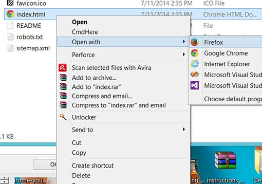
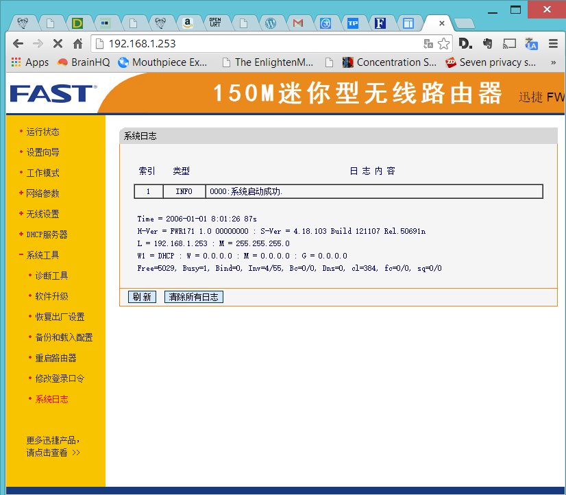
To load your English firmware, you must set up a TFTP server on your host machine. In Windows, you can use TFTPD32. If you don’t know how to use TFTPD32, I have a description in this article. Point your TFTP server to the directory containing your firmware file, and type the name of the file into the box containing fwr171v1-cn-up.bin below: fwupg-sm   
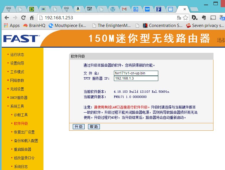
Click the bottom left button in the dialog, and a progress bar will appear, indicating that the firmware is being loaded. Once it is done, the device will automatically reboot, and your host computer should see a new WiFi AP with SSID TP-LINK_xxxxxx, where xxxxxx are the last 6 digits of your FW171’s MAC address. This indicates that you have successfully loaded your English TP-WR702N firmware! Next, set your host computer’s Ethernet port to DHCP, and plug the FW171 into it. Your host computer will receive an IP number in the range of 192.168.0.X. Point your web browser to the TL-WR702N’s IP number 192.168.0.254, and log in with user admin, password admin.

Downloads: English TL-WR702N firmware for FW171

OpenWrt: Cross-compiling libmicrohttpd for TL-WR703N

Recently, I’ve been developing embedded webapps using node.js. Unfortunately, node.js is a bit bloated for resource-constrained platforms, such as the TL-WR703N running OpenWrt. Not only is it too large to fit into flash memory, requiring an external USB drive to run EXTROOT, but I’ve even encountered circumstances where I’ve been running out of RAM. Thus, I’ve been looking for a lean & mean HTTP library written in C. Right now, my top two candidates are axTLS and libmicrohttpd. Since it’s impractical to host a toolchain on the TL-WR703N, we have to cross-compile everything, which can be a bit of a chore to set up. The first step is to download and unpack the source code:

% wget http://ftp.gnu.org/gnu/libmicrohttpd/libmicrohttpd-0.9.38.tar.gz
% tar xzvf libmicrohttpd-0.9.38.tar.gz

If you don’t already have an OpenWrt toolchain set up, you can download and install it as follows:

% wget http://downloads.openwrt.org/attitude_adjustment/12.09/ar71xx/generic/OpenWrt-Toolchain-ar71xx-for-mips_r2-gcc-4.6-linaro_uClibc-0.9.33.2.tar.bz2
% bzip2 -dc OpenWrt-Toolchain-ar71xx-for-mips_r2-gcc-4.6-linaro_uClibc-0.9.33.2.tar.bz2 | tar xvf –

Next, we need a build script. Save the bash script below as build_libmicrohttpd_mipsbe.sh:

[code language=”bash”]
#!/bin/bash
#
# compile libmicrohttpd for ar71xx (mipsbe)
#

export BASEDIR=$(pwd)

### begin configuration

# node src directory
export SRCDIR=libmicrohttpd-0.9.38

#adjust STAGING_DIR and TOOLDIR below based on location of your toolchain
#ToolChain
export STAGING_DIR=${BASEDIR}/OpenWrt-Toolchain-ar71xx-for-mips_r2-gcc-4.6-linaro_uClibc-0.9.33.2/toolchain-mips_r2_gcc-4.6-linaro_uClibc-0.9.33.2
#export STAGING_DIR=${BASEDIR}/openwrt/attitude_adjustment/staging_dir

export TOOLDIR=${STAGING_DIR}/toolchain-mips_r2_gcc-4.6-linaro_uClibc-0.9.33.2

### end configuration

export TARGET_PATH=${BASEDIR}/${SRCDIR}-mipsbe
export PREFIX=${TOOLDIR}/bin/mips-openwrt-linux-
export LIBPATH=${TOOLDIR}/lib/

# MIPS cross-compile exports
export CC=${PREFIX}gcc
export CXX=${PREFIX}g++
export AR=${PREFIX}ar
export RANLIB=${PREFIX}ranlib
export LINK=${PREFIX}g++
export CPP="${PREFIX}gcc -E"
export STRIP=${PREFIX}strip
export OBJCOPY=${PREFIX}objcopy
export LD=${PREFIX}g++
export OBJDUMP=${PREFIX}objdump
export NM=${PREFIX}nm
export AS=${PREFIX}as
export PS1="[${PREFIX}] \w$ "
export LDFLAGS=’-Wl,-rpath-link ‘${LIBPATH}

rm -rf ${TARGET_PATH}
mkdir ${TARGET_PATH}
cd ${SRCDIR}
make clean
make distclean
./configure –prefix=${TARGET_PATH} –host=mips-openwrt-linux-uclibc –without-snapshot –with-mips-float-abi=soft
make
make install
[/code]

If your toolchain is in a different place from the STAGING_DIR specified in the script, adjust it to point to the proper location. Finally, execute the build script:

% sh build_libmicrohttpd_mipsbe.sh

After the build is complete, you can test it out by transferring one of the example files to your TL-WR703N running OpenWrt. A good candidate would be src/examples/fileserver_example. In addition to the executable, you also need to get the shared library onto your OpenWrt machine. It is built into a strange location: src/examples/microhttpd/.libs/libmicrohttpd.so.10. Put the file in /usr/lib/libmicrohttpd.so.10 on your target machine. Finally, you should be able to execute fileserver_example on the target machine.

Windows 8: How to Fix Windows Update and/or Windows Defender Check for Updates Failure

I had a very irritating problem with my Acer Aspire V5 notebook computer running Microsoft Windows 8.1 for the past several months. The computer was not able to update itself. When I launched Windows Update, it would just hang forever checking for new updates, so I couldn’t even figure out what updates were needed, let alone download and install it. At the same time, Windows Defender would constantly bug me that my virus definitions needed to be updated, but every time I tried to download the updates, it would either hang forever, or fail.

After wasting many hours trying to find a solution, I finally fixed it yesterday. It turns out that the two problems were related. It seems that Windows Defender uses Windows Update as a back end to download its virus definitions, because my fix got both of them working again. So, without adieu, here is the procedure for getting your Windows Update and Windows Defender to successfully check for updates again:

Step 1: Download Windows Update Powershell Module

Open up your favorite Web Browser, and point it to:

http://gallery.technet.microsoft.com/scriptcenter/2d191bcd-3308-4edd-9de2-88dff796b0bc

Click the blue box labeled PSWindowsUpdate.zip and save the file to your computer.

(Direct download for PSWindowsUpdate.zip: http://gallery.technet.microsoft.com/scriptcenter/2d191bcd-3308-4edd-9de2-88dff796b0bc/file/41459/43/PSWindowsUpdate.zip)

Step 2: Extract files from PSWindowsUpdate.zip

Extract the files in PSWindowsUpdate.zip to %WINDIR%\System32\WindowsPowerShell\v1.0\Modules.

If you do this step correctly, in most computers, you will have a folder called C:\Windows\System32\WindowsPowerShell\v1.0\Modules\PSWindowsUpdate

Step 3: Launch Windows Power Shell with Administrator Privileges

From the Control Panel, open Administrative Tools. Right click Windows Powershell ISE, and select Run As Administrator:

Image1

Step 4: Import the PSWindowsUpdate Module

Type Import-Module PSWindowsUpdate into the PowerShell:

Image2

Step 5: Change Execution Policy

In the PowerShell, type:  Set-ExecutionPolicy RemoteSigned

PS> Set-ExecutionPolicy RemoteSigned

You will get a security warning dialog. Click the Yes button. You don’t have to worry, because we downloaded the module directly from Microsoft.

Step 6: Run Get-WUInstall

In the Powershell, type Get-WUInstall:

PS> Get-WUInstall

Answer any prompts which may come up. My system had a lot of updates pending, so I let the module download and install them all. After it’s done, your Windows Update and Windows Defender will work correctly again!

Many thanks to the people who came up with this solution. The information came from: http://social.technet.microsoft.com/Forums/windows/en-US/afc7f693-f742-402f-b513-063989b79c2f/windows-81-enterprise-windows-updates

gCode Visualization

I was working on a project today, which had some serious overhangs. I added support material manually, but needed to make sure that slic3r was traversing a usable path through my supports. Usually, I use Repetier Host‘s excellent built-in gCode visualizer, but it only displays a layer at a time, and I needed to see the actual paths followed in each layer. After searching a bit, I found an excellent online visualizer: gcode.ws:

Image3


It is very full featured, with sliders that let you step through your gCode layer by layer, and also line by line within a layer. Additionally, it prints out a lot of useful statistics within your gCode.

While running it in a web browser is handy, since you don’t need to install any software, sometimes, I need to have access to it when I have no Internet access. Fortunately, the visualizer is open source, and is written in javascript, so you can also run it directly from your hard drive. First, download the zip archive from github:

https://github.com/hudbrog/gCodeViewer/archive/master.zip

Unzip the archive, and simply launch index.html. I had security issues running it in Chrome, and it froze up in Internet Explorer, but Firefox runs it just fine. To run it in Chrome, you must launch it with the command line option “–allow-file-access-from-files” in order to lower the security so that it can access files locally, but it doesn’t work if you already have a running copy of Chrome.

On Windows computers, if Firefox isn’t your default browser, you can just right-click index.html, and select Open with->Firefox.

Image3


Many thanks to hudbrog for making this excellent tool.

Slic3r Support Material Frustration

It’s been a few years since I’ve played with Slic3r, so I was eager to play with the current stable version, v1.0.1. One problem I had when playing with earlier versions of Slic3r was that the support material generation was not yet usable. A part I was designing had a big circular overhang in the middle, so it was the perfect opportunity to try out support meterial in v1.0.1 stable. Unfortunately, while the support material worked great for printing, it was almost impossible to remove! The gcode depicted below was generated using the rectlinear pattern:

slic3r101stable

The support material in the above picture is the large circular plug. Notice how it doesn’t leave a gap between the plug and the hole, so it’s completely stuck to the part! It took me almost an hour to carefully dig the support material out with and x-acto knife. Unfortunately, there’s no parameter in v1.0.1 to let you tune the spacing between the support material and vertical walls. Next, after reading that the Slic3r team had rewritten the support material code, I downloaded the latest experimental version, 1.1.4, and tried it. Much better:

slic3r114

Note the sizeable gap between the support plug and the perimeter of the hole. This time, the supports only took a few minutes to remove. The moral of the story? Use a newer version of Slic3r instead of v1.0.1 stable if you want to generate easy to remove support material. An added bonus of v1.1.4 is a new support pattern, called pillars. It looks like this:

pillars

Arduino 1.0.5-r2 for AT90USB1286 and Printrboard

It’s been a few years since I hacked together the copy of Arduino-0022 that’s been floating around the web, which lets you compile and automatically upload Arduino code to an AT90USB1286. This made it a lot easier to develop Arduino code for the AT90USB1286, and in particular to easily modify the Marlin firmware for the Printrboard.

Yesterday, I figured it was high time to add AT90USB1286 support to Arduino 1.0.5-r2. The basic procedure for the modification was to first install Teensyduino, which adds the AT90USB1286 compilation support to Arduino, but only uploads to a Teensy++ 2.0, running PJRC’s proprietary halfkay bootloader. I modified the Teensyduino configuration to also support uploads to targets running the LUFA CDC Bootloader, or via USBtinyISP or USBasp ICSP programmers.

Note that I copy that I modified only runs on Microsoft Windows.
You can download it from github: https://github.com/lincomatic/arduino-1.0.5-r2-at90usb1286
It’s easiest to download it as a zip file: https://github.com/lincomatic/arduino-1.0.5-r2-at90usb1286/archive/master.zip

Once you unzip the archive and launch arduino.exe, you will notice some new entries in the Tools->Board menu:

[USBasp]AT90USB1286
[usbtinyisp]AT90USB1286
[BootloaderCDC]AT90USB1286
[USBasp]Printrboard
[usbtinyisp]Printrboard
[BootloaderCDC]Printrboard

The only difference between the Printrboard and AT90USB1286 entries is that the extraneous USB Type, CPU Speed, and Keyboard Layout submenus are grayed out from the Tools menu.

To load Marlin firmware onto a Printrboard, you will most likely want to use [BootloaderCDC]Printrboard.

Note that unlike my Arduino-0022 hack, the pinMode()/digitalRead()/digitalWrite() functions in version currently only support the pins that are exposed on the Teensy++ 2.0. This is because I haven’t yet had the time to figure out how to add in the remaining AT90USB1286. However, this limitation doesn’t affect Marlin firmware on the Printrboard, because Marlin uses its own fastio functions, rather than using Arduino digital pin numbers and pinMode()/digitalRead()/digitalWrite(). See pinmap.txt for the currently supported Arduino digital pin numbers.

Thanks again to PJRC for Teensyduino. Teensys are a great alternative to Arduino boards.

Interfacing a TFT_320QVT LCD/Touchscreen/SD to a Teensy 3.0

I’m working on a project which needs a touchscreen LCD. After searching eBay for a while, I noticed that many vendors were selling basically the same 3.2″ 320×240 TFT with resistive touchscreen and SD card reader. Though there were slight variations in the silkscreens, they all had the same model number – TFT_320QVT. I bought mine from digitalzone88 for $12.29. TK0466-1-digitalzone88 TK0466-4-digitalzone88 The board uses a SSD1289 LCD driver IC, and runs on 3.3V. The 3.3V voltage is incompatible with the typical Arduino, which runs at 5V (some vendors have created shields to interface it to an Arduino Mega). However, I purchased the TFT_320QVT with the intention of interfacing it to a Teensy 3.0, which runs at 3.3V. I noticed that there were not enough through-hole I/O pins on Teensy 3.0 to simultaneously interface to the LCD, touchscreen, and SD card. This necessitated the usage of the Teensy 3.0’s additional I/O pins, accessible only via solder pads on its underside: teensy3b To facilitate access to the 14 solder pads, I attached some header pins to piece of stripboard, and soldered 40AWG wire-wrap wire to between the pads and headers: extenderThe Teensy 3.0 runs on PJRC’s specially modified version of Arduino – Teensyduino. The task was to find compatible Arduino libraries. First order of business was the LCD. I searched the web, and found that dawnmist had spent a considerable effort in modifying Henning Karlson’s UTFT to work with the Teensy 3.0. Unbeknownst to me at the time, dawnmist’s modified UTFT is actually bundled with Teensyduino!

Next, was to get the touch screen working. It turns out that the current version of Henning Karlson’s UTouch is compatible with the Teensy 3.0.

For the SD slot, I tried the version of the Arduino SD library that’s bundled with Teensyduino. Unfortunately, though the SD library works with the TFT_320QVT’s SD reader, it stops working if you instantiate a UTFT object in the sketch. I tried sdfatlib, and found that not only does it work w/ the Teensy 3.0, but it coexists fine with UTFT. The only catch I found is that it works only with SPI_HALF_SPEED. When I set it to SPI_FULL_SPEED, it stops working.

Here is the Teensy 3.0 running UTFT‘s demo sketch on the TFT_320QVT: utft

Below is the step-by-step procedure to getting the TFT_320QVT up and running with Teensy 3.0:

Step 1: Install the libraries

1. UTFT: Run the Teensyduino installer, and when the Libraries to Install dialog is displayed, check the box next to UTFT in the Choose Additional Libraries to Install combobox. (Note: Henning Karlson’s latest UTFT also works with Teensy 3.0, but my discussion below will show how to interface to the UTFT that’s bundled with Teensyduino 1.18).

2. UTouch: Download UTouch.rar. Use WinRar or 7-zip to extract the enclosed UTouch folder. From the Arduino IDE pull-down menu, use Sketch->Import Library->Add Library… to install the extracted UTouch folder. Alternatively, you can just copy Utouch/ to your arduinosketchbook/libraries directory.

3. sdfatlib: Download the latest version of sdfatlib. From the Arduino IDE pull-down menu, use Sketch->Import Library->Add Library… to install the downloaded sdfatlibyyyymmdd.zip file. You can alternatively just extract the SdFat/ folder into your arduinosketchbook/libraries directory.

Step 2: Wire it up

1. LCD: dawnmist‘s modified UTFT library that’s bundled with Teensyduino has a configuration file: arduinofolder\libraries\UTFT\hardware\arm\HW_Teensy3.h. Inside HW_Teensy3.h, there are 3 options for the LCD pin assignments: USE_B_D_PORTS, USE_C_D_PORTS, and USE_USER_PORTS. By default, the file has

#define PORTS USE_B_D_PORTS

enabled. USE_B_D_PORTS gives the best performance when your sketch needs to use SPI (which is needed for the SD card slot). USE_C_D_PORTS gives the fastest performance, but is incompatible with SPI. USE_USER_PORTS allows you to configure arbitrary pins (by changing the DB_0-DB_16 #defines), but results in the slowest performance. I elected to use the default USE_B_D_PORTS setting.

2. SD card reader: The SD card reader works via SPI, so it needs to use SD_DIN->DIN (MOSI – 11), SD_DO->DOUT (MISO – 12), SD_CLK->SCK (13), and one of the chip select pins, CS0-CS4 (10,9,20,21, or 15). I chose to use SD_CS->CS4 (15).

3. Touchscreen: The touchscreen uses 5 pins, T_DIN/T_DO,T_CS/T_CLK/T_IRQ, which can be assigned to any arbitrary free GPIO pins.

Below is a chart of my pin assignments:

Teensy_pin = TFT_320QVT_pin
0 = LCD_DB4
1 = LCD_DB5
2 = LCD_DB8
3 = LCD_LED_A (backlight)
5 = LCD_DB15
6 = LCD_DB12
7 = LCD_DB10
8 = LCD_DB11
9 = LCD_REST (RESET)
11 = SD_DIN (MOSI)
12 = SD_DO (MISO)
13 = SD_CLK (SCK)
14 = LCD_DB9
15 = SD_CS
16 = LCD_DB0
17 = LCD_DB1
18 = LCD_DB3
19 = LCD_DB2
20 = LCD_DB13
21 = LCD_DB14
22 = LCD_WR
23 = LCD_RS
24 = T_CLK
25 = LCD_DB7
26 = T_CS
27 = T_DIN
28 = T_DO
29 = T_IRQ
32 = LCD_DB6

LCD_RD needs to be pulled up to 3.3v

I have created a sketch, UTFT_UTouch_SdFat_teensy3, that simultaneously demonstrates the LCD, touchscreen, and SD card by modifying the UTouch demo sketch. Below are the lines which are critical to configuring it to work with the above pin connections:
[code language=”c”]
#include <UTFT.h>
#include <UTouch.h>
#include <SdFat.h>

// bitmap file to load as background.
// must be 320×240 and in format output by ImageConverter565
char bkgRaw[] = "ade.raw";

uint8_t sdCS = 15; // SD_CS – chip select
SdFat sd;
SdFile inFile;

uint8_t lcdRS = 23;
uint8_t lcdWR = 22;
uint8_t lcdCS = 4;
uint8_t lcdReset = 9;
uint8_t lcdBacklight = 3; // must be a PWM pin for variable brightness
uint8_t lcdBacklightBrightness = 255; // 0-255
UTFT myGLCD(SSD1289, lcdRS, lcdWR, lcdCS, lcdReset);

// Initialize touchscreen
uint8_t t_Clk = 24;
uint8_t t_CS = 26;
uint8_t t_DIn = 27;
uint8_t t_DOut = 28;
uint8_t t_IRQ = 29;
UTouch myTouch(t_Clk, t_CS, t_DIn, t_DOut, t_IRQ);
[/code]

The file displays a bitmap, ade.raw, as the background. Before running the sketch, copy ade.raw to a FAT-formatted SD card, and insert it into the TFT_320QVT’s SD card slot.

You can also substitute your own bitmap file. To create a .raw file, first create a 240×320 pixel jpg, png, or GIF file. Run it through either imageconverter565.exe (bundled with UTFT) or the online ImageConverter 565 make sure to select Convert to .raw file and Target Platform Arduino (AVR).

Here’s what UTFT_UTouch_SdFat_teensy3 looks like when it’s running:
btntest

Many thanks to dawnmist, and the others who figured out how to get UTFT working with the Teensy 3.0.

Downloads:
UTFT_UTouch_SdFat_teensy3
UTFT_demo_tft_320qvt_teensy3

Links:
I obtained much of the information I needed from these pages:
dawnmist – screen working … finally
Teensy 3.0 – driving an SSD1289 with utft

Arduino IDE suddenly freezing up? Here’s how to fix it.

Every once in a while, my Arduino IDE suddenly takes forever to launch, sticking at the splash screen for a long time. Even after it launches, it’s still basically unusable, because the pull-down menus also freeze up, and take an eternity to respond. It happens to me every time I download a new Arduino IDE, which is so infrequent that repeatedly forget why it happens, and how to fix it. After ripping my hair out for a while, I start googling until I find the fix.

If you’re experiencing this problem running Arduino on Microsoft Windows, chances are, you have a virtual serial port from a Bluetooth SPP device installed in your system. The problem is that the Arduino IDE is trying to enumerate your system’s serial ports in order to locate the attached Arduino devices, and the code takes a long time to timeout. Luckily, user eried in the Arduino forums figured out what was happening, and posted a fix in the thread: Road to solve the delay in Arduino IDE. He has graciously come up with a workaround, and shared it with us.

The fix is easy. Simply download his rar file, extract his new rxtxSerial.dll, and replace the version that’s currently in the same directory where your arduino.exe resides. I’ve also attached a zip archive of the file below, for those people who don’t want to install WinRAR in order to get the new rxtxSerial.dll. Thanks, eried!

Downloads: rxtxSerial-2.2_fixed_2009-03-17.zip

ITEAD Studio IBOX – Part 3: Installing Java and Processing

ITEAD Studio asked me how to install Processing 2.1.1 on Debian 7.0 running on the IBOX, because they want to use the IBOX as a Lampduino controller. This article describes the installation procedure. All of the commands must be typed into a shell Terminal.

1. Install openjdk and librxtx

# apt-get update
# apt-get install openjdk-7-jdk librxtx-java

2. Download and extract Processing for 32-bit Linux

# cd /opt
# wget http://download.processing.org/processing-2.1.1-linux32.tgz
# tar xzf processing-2.1.1-linux32.tgz

3. Remove the x86 Java bundled with Processing and link to OpenJDK

# cd processing-2.1.1
# rm -rf java
# ln -s /usr/lib/jvm/java-7-openjdk-armhf java

4. Modify the serial support for ARM

Unfortunately, Processing 2.1.1 no longer uses RXTXcomm.jar, so we have to copy the serial support from Processing 2.0.3, and then modify it for ARM:

# cd /opt
# wget http://download.processing.org/processing-2.0.3-linux32.tgz
# tar xzf processing-2.0.3-linux32.tgz
# rm -rf processing-2.1.1/modes/java/libraries/serial
# mv processing-2.0.3/modes/java/libraries/serial processing-2.1.1/modes/java/libraries
# rm -rf processing-2.0.3*
# cd processing-2.1.1/modes/java/libraries/serial/library
# rm RXTXcomm.jar
# cp /usr/share/java/RXTXcomm.jar .
# rm linux32/librxtxSerial.so
# cp /usr/lib/jni/librxtxSerial.so linux32

Congratulalions, you have a working copy of Processing! Start Processing by launching /opt/processing-2.1.1/processing

** Optional Steps Below **

Processing complains that it doesn’t like OpenJDK when it’s launched. If you want to accelerate the performance, and improve compatibility, you can follow the additional steps below and install the hard float version of Oracle Java 7 SE Embedded. The OpenJDK 7 that’s installed via apt-get ignores the A20’s hardware floating point unit, and instead uses software emulation.

5. Download Java SE Embedded 7 update 51

Unfortunately, Oracle makes you accept a license agreement, which requires cookies, making download a lot messier than just running wget.
Use a web browser to navigate to the Java SE Embedded Downloads page. Click the Accept License Agreement radio button near the top of the page, and then click the link corresponding to ARMv6/7 Linux – Headful EABI, VFP, HardFP ABI, Little Endian. The next page requires you to log into an Oracle account. If you don’t have one, you can create one for free. Save the file the /opt directory. The included web browser wasn’t working in my copy of ITEAD Debian 7.0. If you need a web browser to download Java, you can use iceweasel:

# apt-get install iceweasel
# iceweasel

6. Install Oracle Java SE Embedded 7

# cd /opt
# tar xzf ejre-7u51-fcs-b13-linux-arm-vfp-hflt-client_headful-18_dec_2013.gz

The .gz file will extract into a directory at /opt/ejre1.7.0_51.
7. Modify Processing to use Oracle Java SE Embedded 7

# ln -s /opt/ejre1.7.0_51 /opt/processing-2.1.1/java

When you launch Processing 2.1.1, it should no longer complain that it doesn’t like the version of Java that you’re using. I found that the hardware floating support Oracle Java 7 gives a big speedup in any code that has floating point computations.

Previous Article: ITEAD Studio IBOX – Part 2: Booting up Debian Linux 7.0

Noritake 24×6 Character VFD Module

I’ve always thought VFDs were pretty cool. They used to be the rage in high end consumer electronics. Back in the mid 70’s, I built a VFD alarm clock. Recently, I got my hands on a modern VFD module to play with. The Noritake-itron SCK-Y100-24063-N14 is a very flexible 24×6 character VFD module in the same form factor of a 20×4 character LCD module. It is a member of Noritake’s CU-Y series VFDs.

vfdardu

Overview

  • 5V supply voltage
  • serial (asynchronous and synchronous) and 8-bit parallel communication
  • CMOS signal and RS-232 (+-15V) voltage compatible
  • jumper-selectable baud rate: 9600, 19200, 38400(default), 115200.
  • extensive built-in character sets: USA, European, Japanese (Katakana only), Multilingual – various fonts and symbols, Canadian and French, Nordic, WPC1252 – european fonts and symbols, Cyrillic, Latin, Portuguese, PC858 – european fonts and symbols
  • adjustable brightness
  • locally selectable brightness for highlighting (useful for implementing menus)
  • double width, and double width & height characters

The video below compares the Noritake 26×6 VFD to a 20×4 LCD. The characters are noticeably smaller on the VFD due to the higher density, but still quite readable.

This page shows some of the versatility of the Noritake VFD: Versatile Character Display CU-Y Series

The VFD comes pre-configured to operate in async serial mode at 38400 baud. It isn’t necessary to use a UART to talk to the VFD; any GPIO pins will suffice. A minimum of 2 pins are needed, for SIN (input) and SBUSY (output). A third GPIO pin can be connected to RESET (input). I hooked mine up to an Arduino UNO as follows:

D2 -> SIN
D3 -> SBUSY
D4 -> RESET

Here’s what it looks like from the front, running Noritake’s Arduino menu demo:

vfdfront

The lower contrast on the left side of the photo is due to my camera’s reflection – the glass is very reflective. Note the highlighting via localized variations in brightness. Here’s what it looks like with a blue filter on top (again, apologies for the reflections – it actually looks a lot better than this photo):

vfdblue

Though my photos are crap, the display is quite easy to read indoors. I wouldn’t recommend it for outdoor use, however, or anywhere that you expect direct sunlight.

Back view:

vfdback

The 10-pin  jumper block on the top center is used for configuration, and the 14-pin jumper block on the bottom right is used only for parallel mode.

The writing speed of this VFD is very fast. Running in async serial mode on an Arduino UNO at 38400 baud, I was able to output 120 characters in a mere 38ms, which is about 3x faster than LiquidTWI2 can muster, even after the I2C bus is tweaked (and over 100x faster than LiquidTWI2 w/o I2C bus frequency tweaking). Unfortunately, Noritake’s Arduino library doesn’t compile on a Teensy 3.x, because it contains AVR assembly code in a timing function, and calls _delay_us(), which isn’t implemented on the Teensy 3.x. On the other hand, it should not be hard to replace these two functions. To use the Noritake VFD with Arduino, first download the Arduino code library. From the Arduino IDE’s pull-down menu, use Sketch->Import Library…->Add Library... to import Arduino_Noritake_VFD_CUY.zip. Include the following headers into your sketch:

[code language=”c”]
#include <CUY_Interface.h>
#include <CUY_Serial_Async.h>
#include <Noritake_VFD_CUY.h>
[/code]

Two classes need to be instantiated:

[code language=”c”]
CUY_Serial_Async interface(38400,2, 3, 4); // SIN,BUSY,RESET
Noritake_VFD_CUY vfd;
[/code]

Here is what initialization looks like:

[code language=”c”]
void setup() {
delay(500); // wait for device to power up
vfd.begin(24, 4); // 24×4 character module
vfd.interface(interface); // select which interface to use
vfd.isModelClass(Y100);
vfd.CUY_init(); // initialize the module
}
[/code]

Note that Noritake chose to implement only partial compatibility with the LiquidCrystal library.  So while vfd.print(s) is supported, vfd.setCursor(x,y) is not; one has to instead call vfd.CUY_setCursor(x,y). The Noritake_VFD_CUY class methods are declared in Noritake_VFD_CUY.h. Noritake includes a few sample sketches, which you can access from Arduino’s menu via File->Examples->CUY.

Noritake also provides a handy host program, which lets you configure and test the display without a microcontroller.

cue-y_373x350

To use the program, connect the VFD to a PC running Microsoft Windows via a Serial->USB adapter, such as an FTDI cable. Using the Serial->USB adapter opens up the possibility of using the VFD  as a USB auxilliary display for a PC.

The Noritake SCK-Y100-24063-N14 is a very cool device, and I’m looking forward to building a project with it.

Resource Links

SCK-Y100-24063-N14 Overview 
CU-Y: Y-Series Evaluation Software
Code Library
Arduino Library with examples
Sample C++ code and configuration/hookup
How to use custom fonts
How to use the built-in font tables
How to use the font magnification command
How to create a menu using the highlight effect