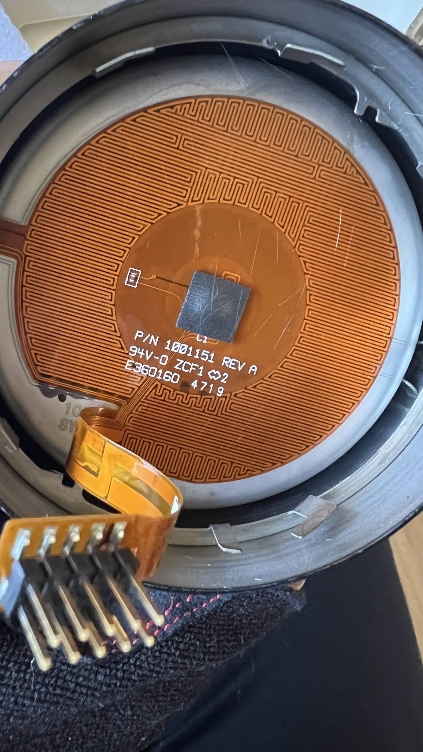
My previous article left off with the task of figuring out what kind of temperature sensor is in the Ember Mug 2. I removed the black rubber retaining ring in the bottom of the mug, and then the 2 aluminum plates which cover the white insulation disc easily came out. Behind it was this:
The very long grid of PCB traces is the heater. There are 3 wires going off into a narrow strip on the left of the photo above to a mystery component that’s sandwiched between the inside/outside of the mug. I think it’s glued in, and can’t be accessed w/o destroying it.
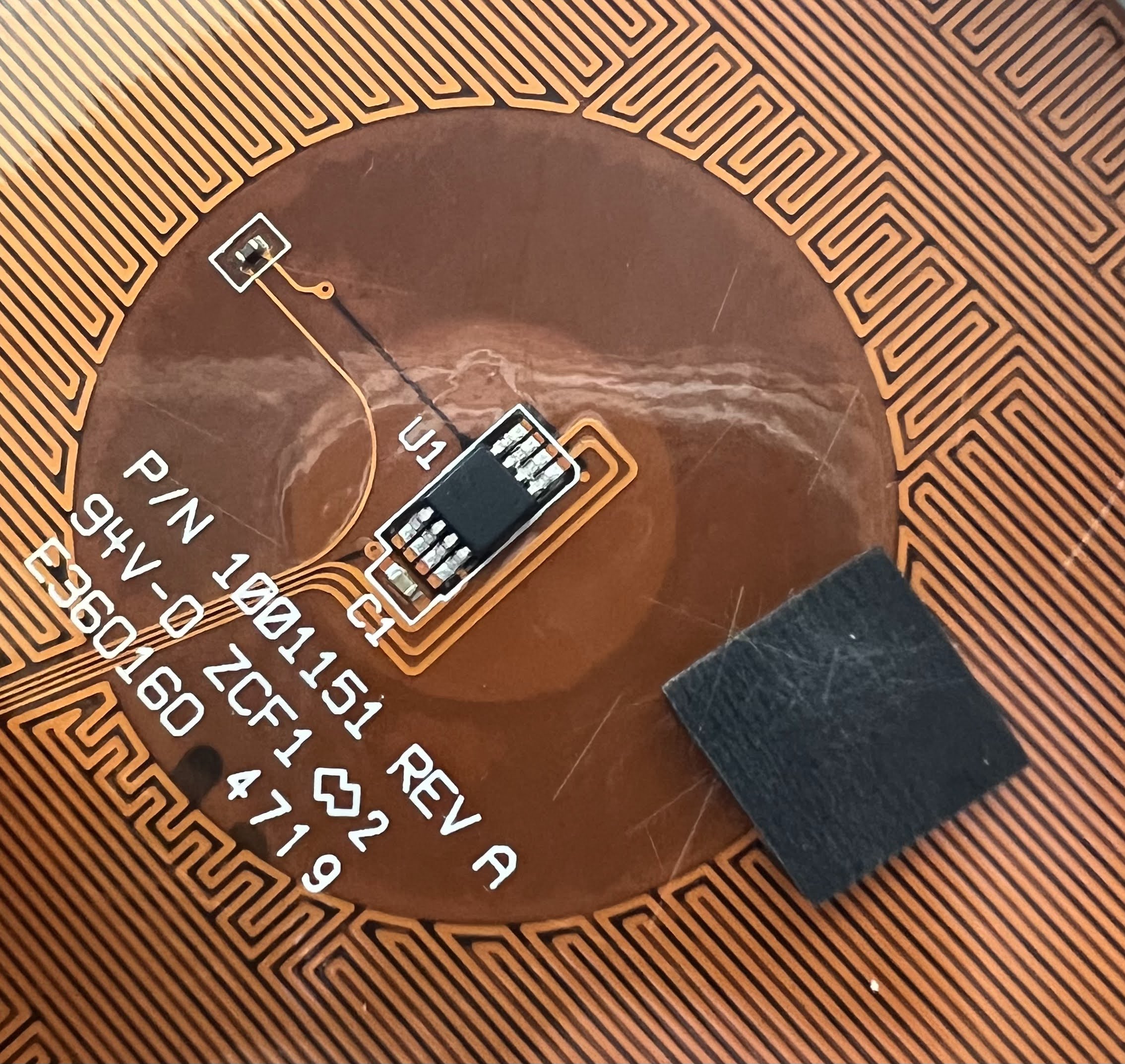
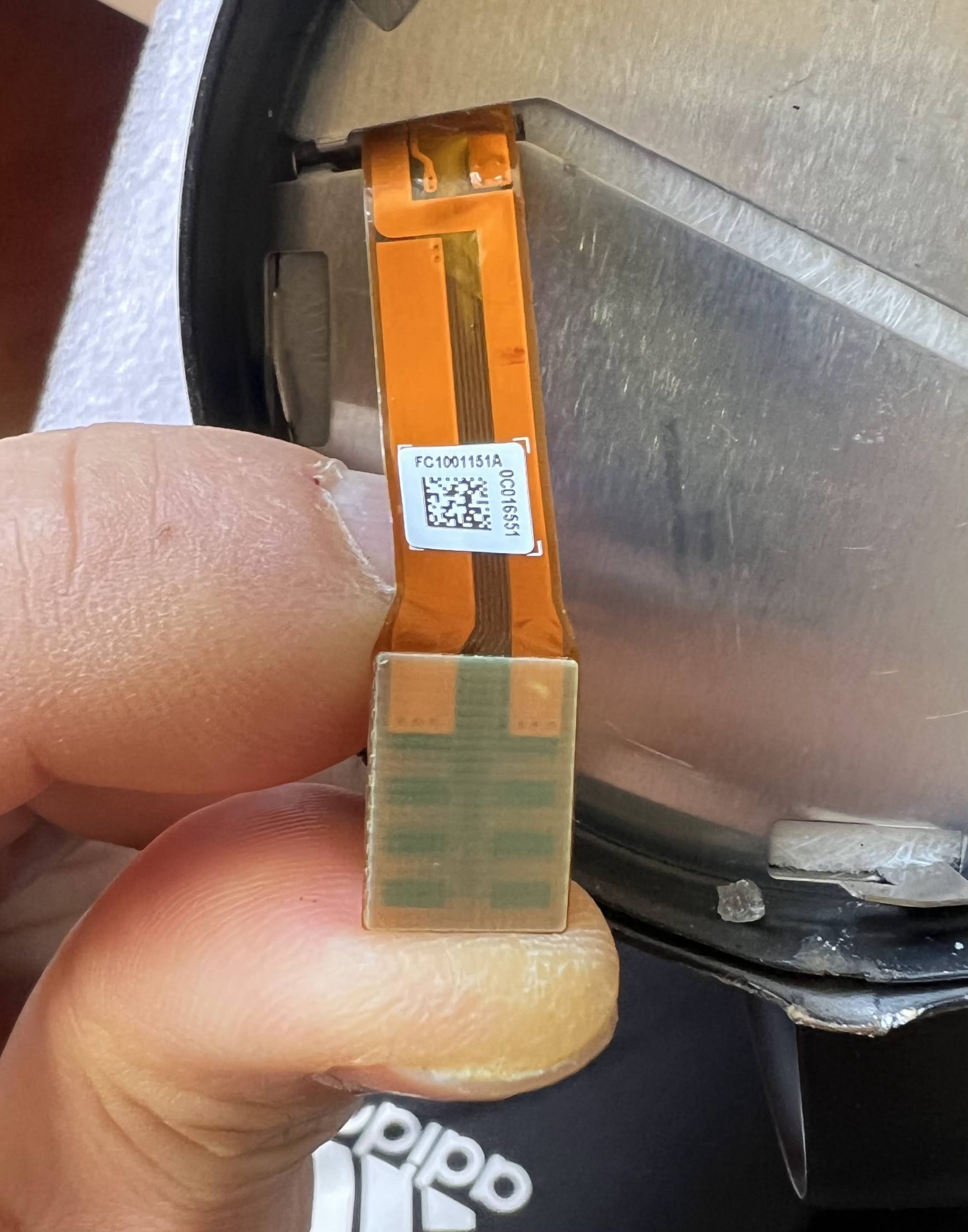
And below the black rubber square is this:
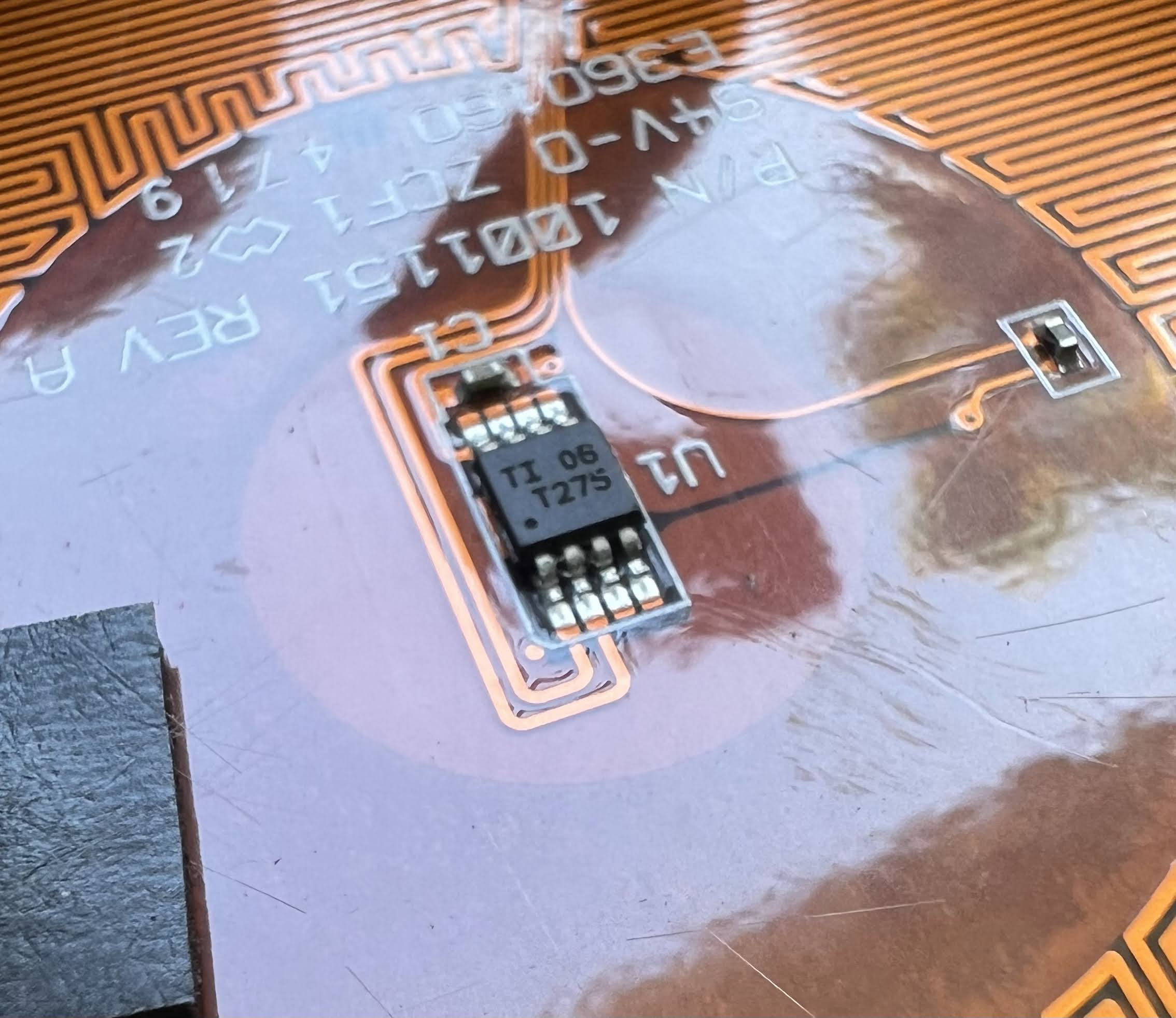
Is U1 the temperature sensor? Here is a close up:
The temperature sensor is just a common part, a TMP275. I have already interfaced a TMP275 to an ESP32 for a previous project of mine. There is plentiful library code already written for reading a TMP275/LM75.
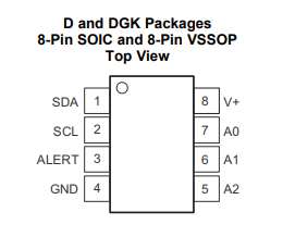
Here is the pinout of the TMP275:
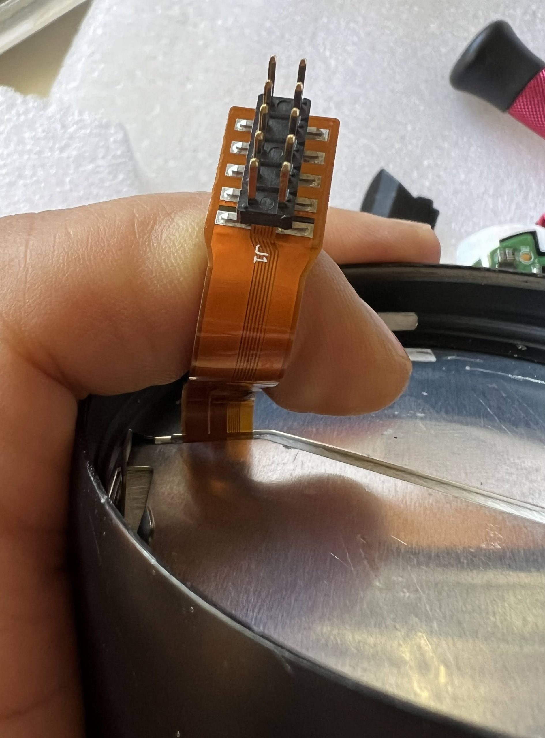
The 2×5 pin connector on the end of the flex cable is labeled J1. Looking at it from the pins side, and w/ J1 on the top, here are the connections I’ve figured out so far:
(1) Heater2
(6) Heater1
(2) Heater3
(7) TMP275 GND
(3)
(8) TMP275 SCL
(4)
(9) TMP275 SDA
(5) unlabeled cap- other end of cap to TMP275 A0/A1/A2
(10) TMP275 V+
SCL & SDA need to be pulled up with 5K resistors (these are probably on the main PCB)
I’m not sure what (3) & (4) connect to, but most likely, it’s the mystery component that’s connected by 3 traces up the side of the cup.
The heater connections are a bit puzzling:
Resistance Heater1-Heater2 11.8 ohms
Resistance Heater2-Heater3 13.8 ohms
Resistance Heater1-Heater3 2.4 ohms
It appears that there are 2 heaters in series with a center tap. I’m guessing that both are used in parallel during heating, and only one is used to maintain temperature.
I’ve already spent too much time on this today, so I’ll have to continue in Part 3.
On the surface, the Ember Mug sounds like a completely idiotic product. I mean, who needs a %#$ bluetooth mug? However, I like to drink coffee and tea, and it has been a constant irritant over the years that my coffee or tea are always either too hot or too cold. Especially tea. I tend to sip it over a long period, and it’s always either burning hot or too cold.
One day, my wife got an Ember Mug 2 as a gift. Actually, it turns out to be pretty useful. It keeps your drink at whatever temperature you like. I decided to get myself used Ember Mug 2. I paid $58, which is still way too much, but it’s a lot cheaper than the $150 a new one cost at the time.
The bluetooth is still idiotic. I would much prefer a mug w/ manual temperature control and buttons on the side. The app just complicates things. Furthermore, the firmware is absolute garbage. Since there’s no switch to turn it on or off. It tries to figure out if there’s liquid inside by sensing how fast the temperature changes when the heater is on. Unfortunately, the idiotic firmware also assumes that the mug is empty when you put in a drink that’s too cold. It refuses to heat up, even if you try to override via the app.
One day, I had some cold coffee that had been sitting out too long. I put it in the Ember Mug to warm it up. It refused to heat up my drink, since it was too cold. Being half asleep, I put it in the microwave oven to warm up the drink to a temp where the Ember Mug would recognize that it wasn’t empty. HORROR OF HORRORS! After about 30s, I realized that I had put my non-microwaveable Ember Mug into the oven!!! I turned off the oven, but alas, it was too late. The mug continued to talk to the app for a few minutes, but refused to heat. A few minutes, it completely died, never to wake up again. I’m lucky that I didn’t microwave it long enough to cause the lithium ion battery to catch on fire, and destroy my oven!!!
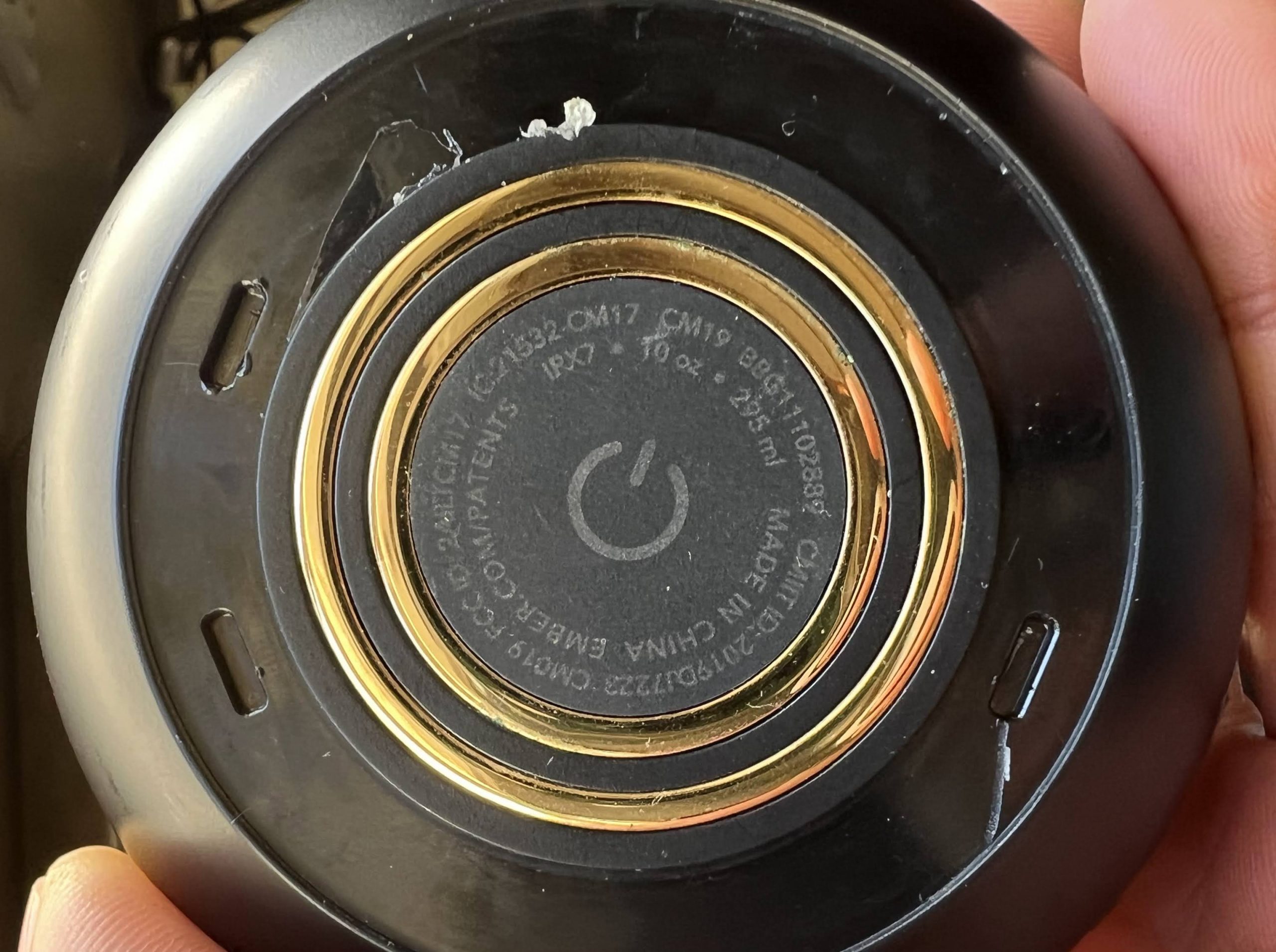
I scoured the Internet, looking for information on how to take it apart. I was hoping that maybe I got lucky, and only the battery got damaged… all I had to do was figure out how to replace it. Unfortunately, I couldn’t find anybody who’d actually taken apart an Ember Mug 2. There is lots of info on taking apart the Ember Travel Mug. However, that one’s bottom is held on with just screws. Not the Mug 2. I took off the rubber gasket on the bottom, and this is what I found:
Unlike the Travel Mug, there are no screws under the gasket. I tried rotating the bottom using the slots, but was not successful.
At this point, I decided to contact Ember tech support, because I heard that they offer cheap replacements to idiots who damage their mugs in the microwave. I emailed Ember tech support, and got this response:
Thank you for reaching out to Ember support! Your request has been received. We are currently experiencing longer reply times, but our team is working diligently to get back to you!
Yeah, right. It’s been 3 weeks, and they still haven’t gotten back to me! <rant> Ember is a shitty company! They sell such a ridiculously expensive disposable, unrepairable product, and have non-existent tech support.</rant> (Update 20240112: Ember actually did try to get back to me 2 days after I opened my support ticket w/ an offer to sell me a new mug at reduced cost, but somehow, the message never got to me. A few hours after I posted this article, I received a message from them saying the ticket would be closed soon due to inactivity.)
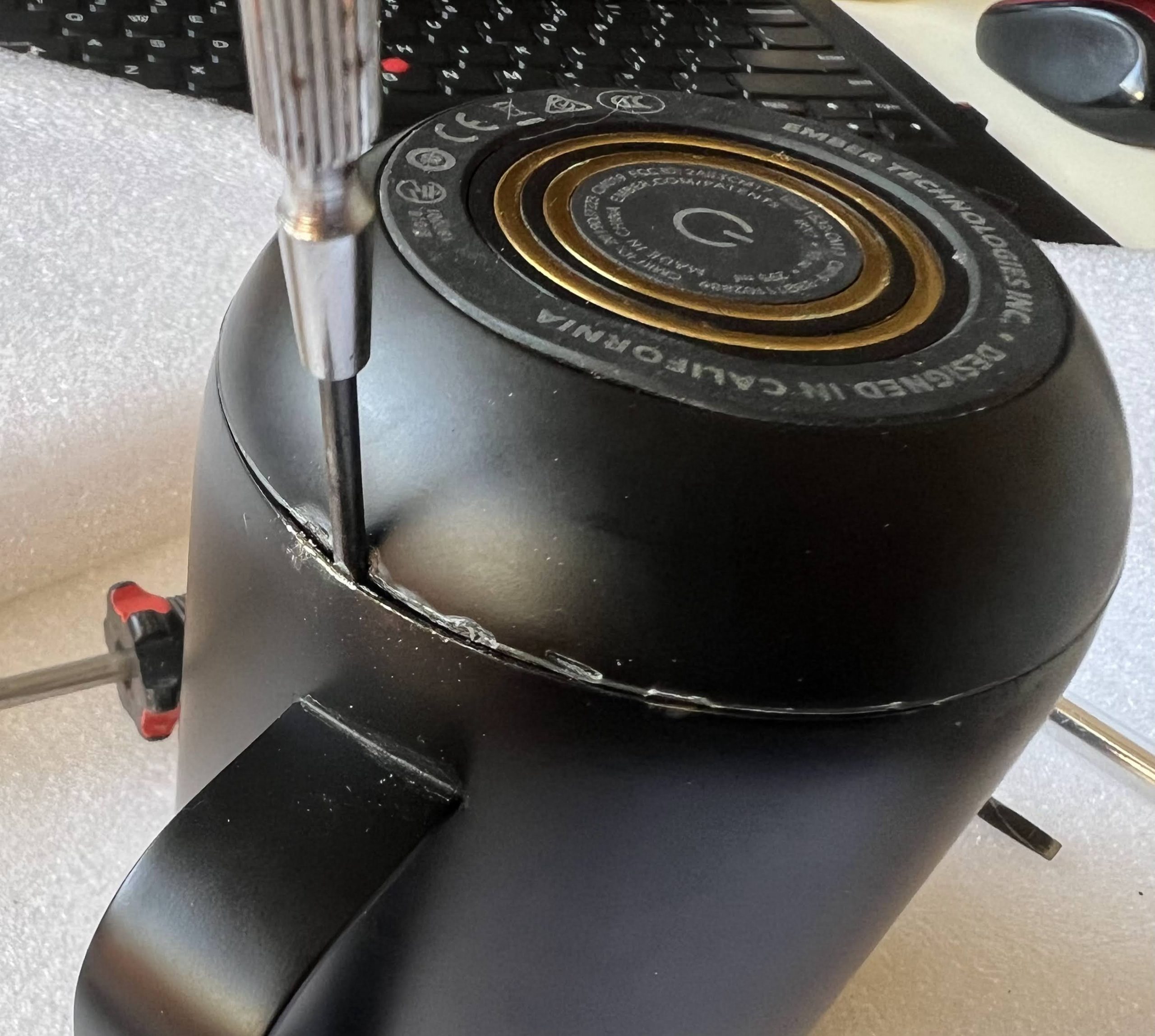
OK, so I decided to disassemble my mug this morning. First, I went around the seam at the bottom with an x-acto knife. It didn’t come loose. Next, I drove a screwdriver into the seam and tried to pry. I chose a spot under the handle, so that the damage wouldn’t be as visible. Finally, I drove my screwdriver between the metal casing and the plastic bottom:
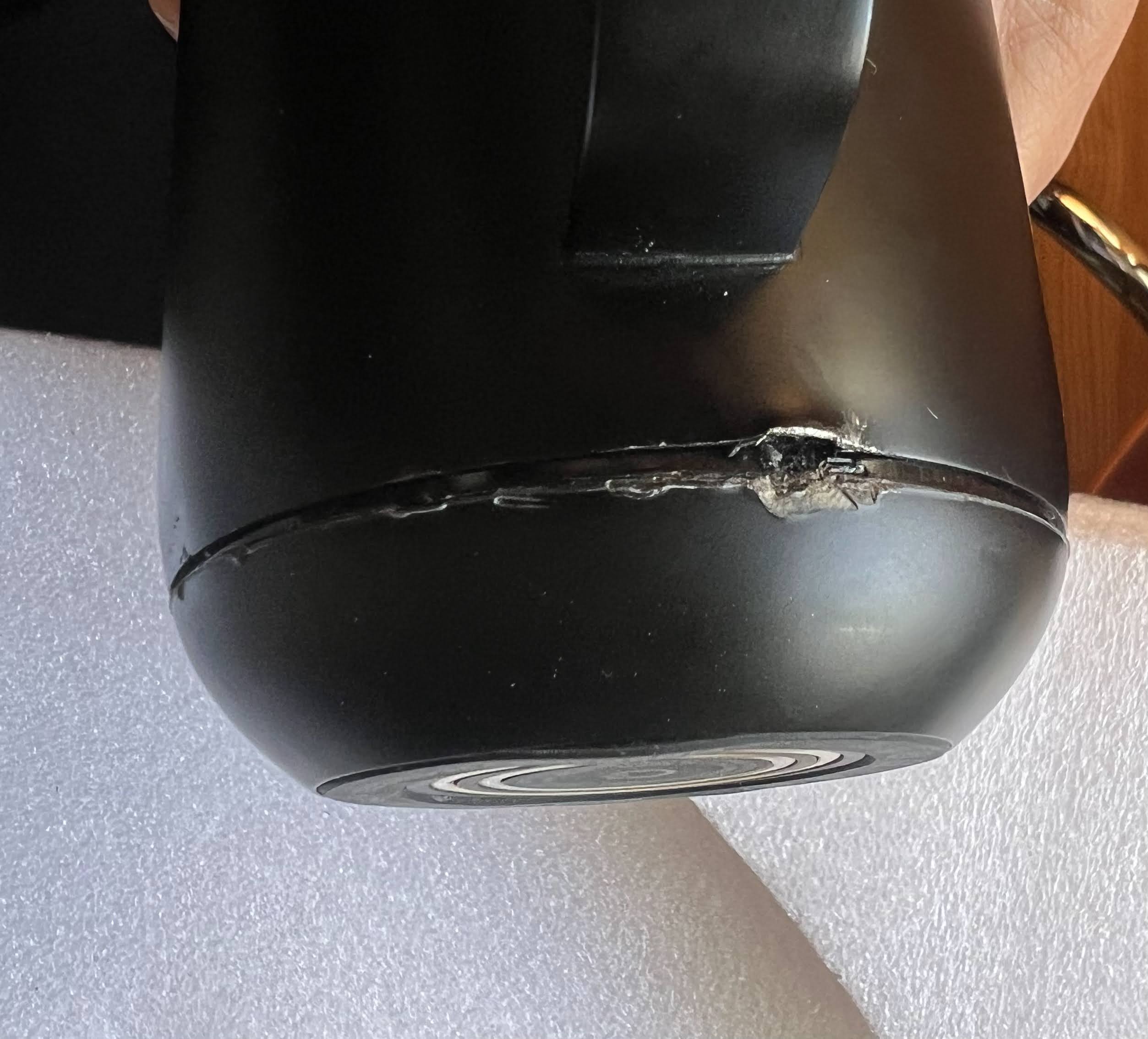
Finally, some movement.
I wedged a bigger screwdriver in, and pried harder. The bottom finally came off:
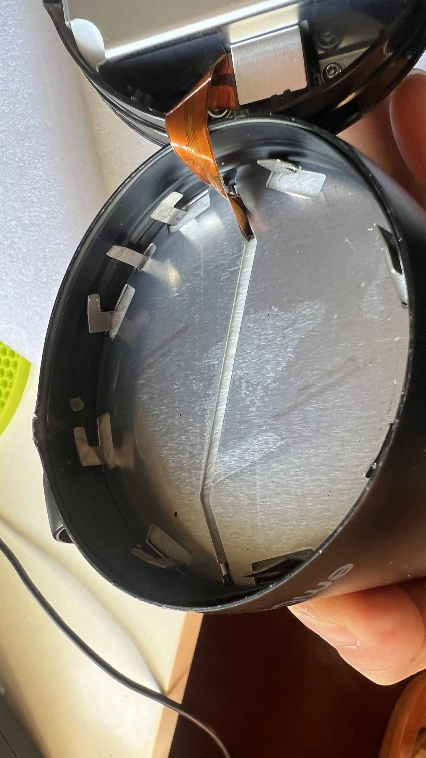
Well lookie there! It’s a twist off bottom after all! It’s too late for me, but I think one could easily drive 3 brads into a piece of wood, lining up w/ the slots I revealed in my first photo … rotate clockwise, and twist off the bottom w/o damaging anything! (UPDATE: The guy who wrote the iFixIt article linked at the bottom claims that the vertical aluminum strip at 10 o’clock prevents the bottom from being twisted off. If that’s the case, it’s a bit of assholery by Ember to keep the mugs from being serviced. Sheesh, it’s bad enough they didn’t just screw the bottom on like w/ the Travel Mug).
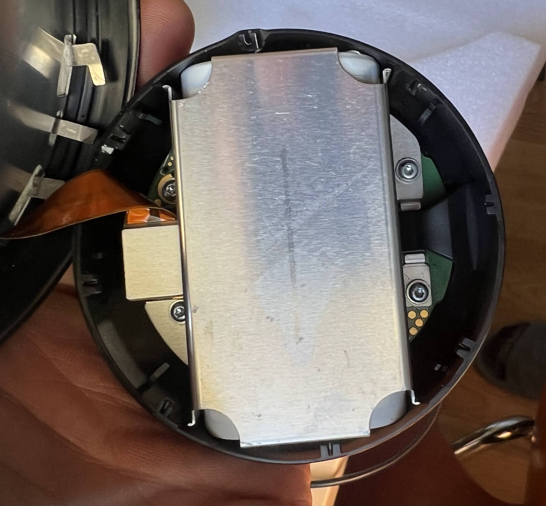
The second I had the case cracked open, the smell of burnt electronics emanated. I instantly knew that I would be dealing w/ more than a damaged battery. The battery is covered by an aluminum plate, which is held on by 4 torx screws:
The 4 torx screws also secure the PCB to the bottom of the case. However, I still couldn’t get the PCB out after taking out the screws. There was a piece of plastic holding down the PCB. You can see it on the right side in the photo below:
I rotated the plastic part out of its retaining slot. Bad idea. It turns out that it’s a light pipe for the RGB LED. Rotating it broke the LED from the PCB:
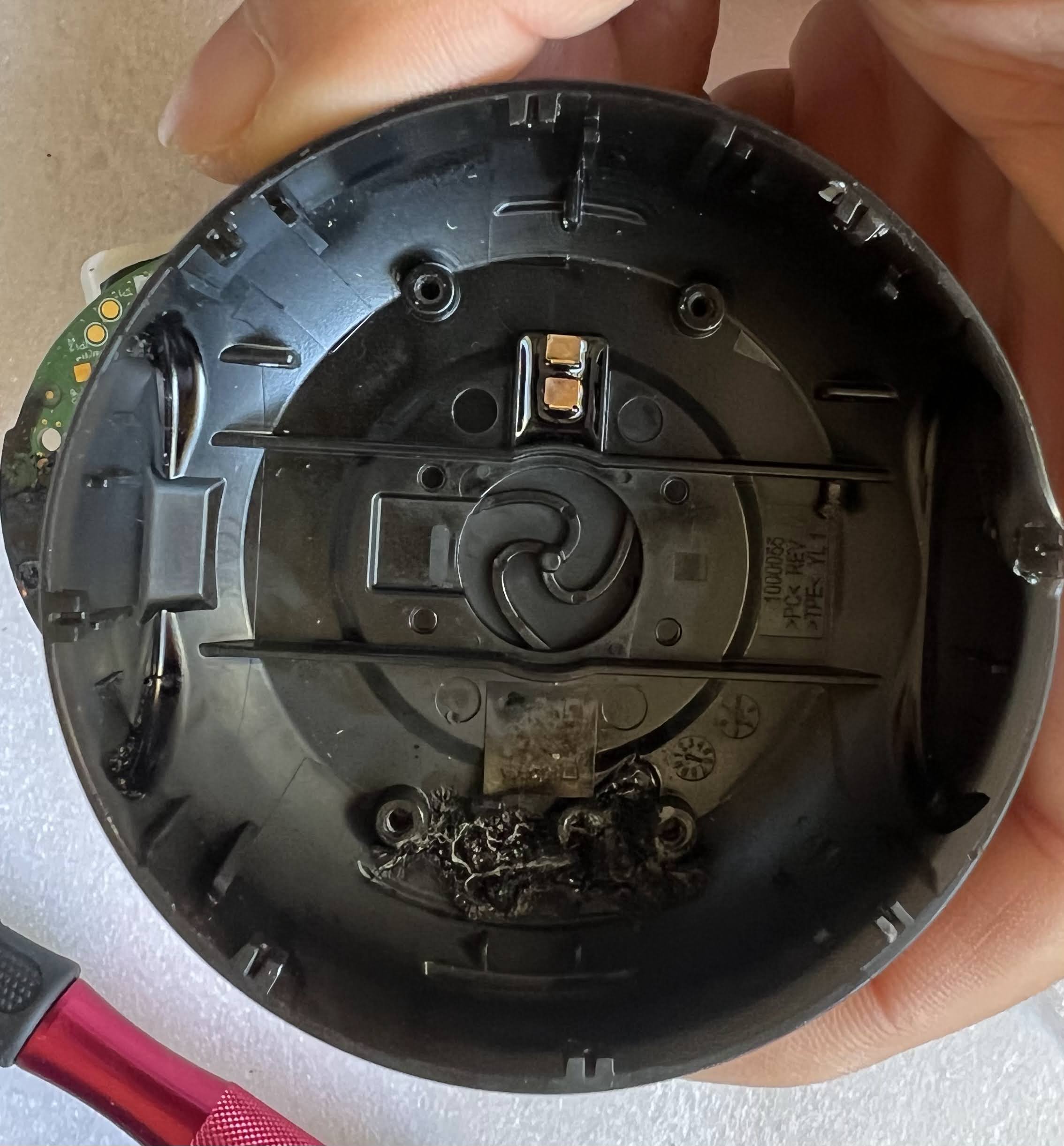
Note that there’s also a monochrome COB LED behind it. I wonder why they need 2 separate LEDs. Here’s what my burnt out plastic bottom looks like inside:
The 2 gold pins in the top center are contacts from the charging ring on the other side. The small circular pin dead center is the pushbutton on the bottom of the mug, which actuates a small SPST switch on the bottom of the PCB
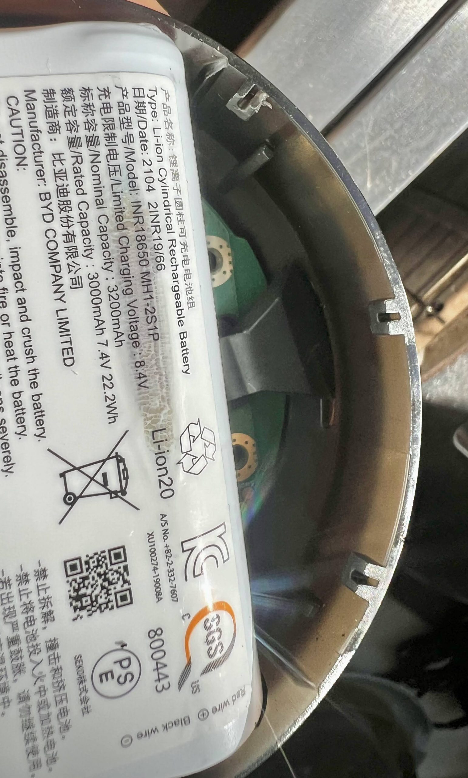
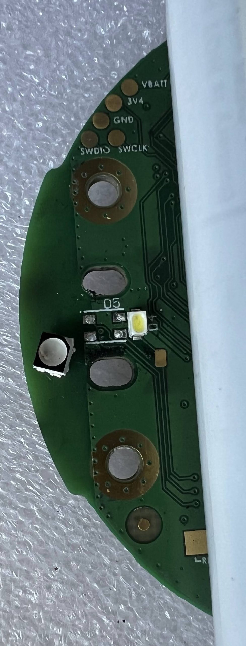
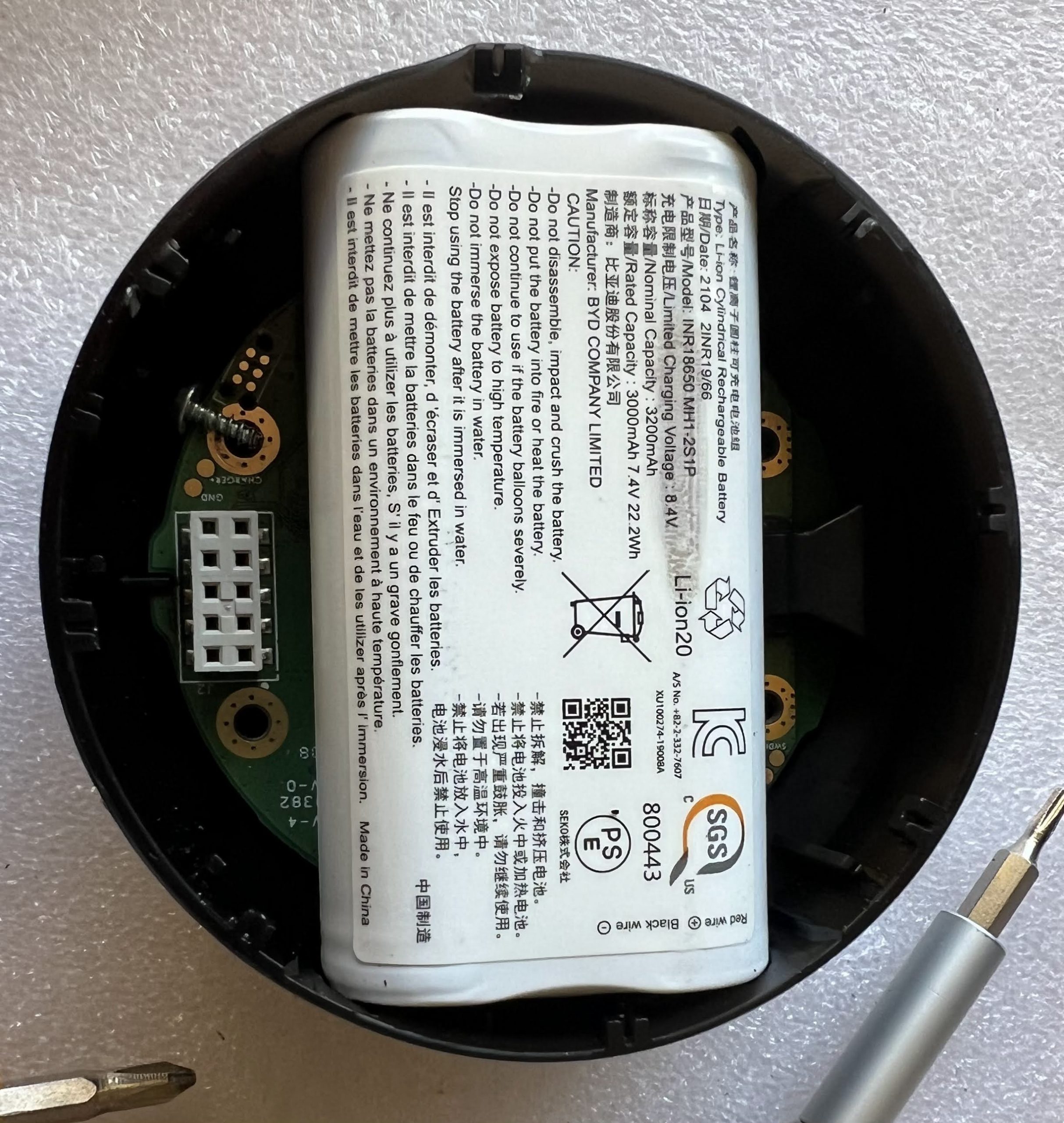
The battery is just a couple standard 18650 cells welded together in a plastic casing, along with the protective circuitry. If you have a Mug 2 with a worn out battery, Ember won’t sell you a replacement. It’s not to hard to just rebuild the pack w/ two new 18650 cells. Here’s my scorched PCB:
The battery connector is on the bottom of the photo above. I measured the voltage between the red and black wires, and it was zero. The yellow and green are sense wires. I am not going to even try to apply 7.4V to the burnt PCB to see if it still works. Here are closeups of the connector that goes into the top of the mug:
It’s obvious that the fat traces are for the heater. Next, I need to figure out what voltage/current the heater needs, as well as what kind of temperature sensor is attached at the other end.
It will be non-trivial, but not too difficult to cook up a circuit w/ an ESP32, along with firmware to resurrect my Ember Mug 2.
UPDATE 2022-08-31: It turns out that in order to program Honda key fobs for cars w/ a push to start button (one button start), you need to be running the beta Honda module V2.01.54, which only runs on 64-bit Android phones, and which you must request from Autel (Instructions here: https://clarity-phev.github.io/Battery-Capacity-Read/AP200_Instructions.pdf). The regular Honda module only programs keys via a separate external module, which plugs into the car’s DLC port. If you aren’t able to obtain the beta Honda module, then you’re out of luck, unfortunately.
Several months ago, I misplaced one of the key fobs from my 2019 Honda Clarity. The MSRP of the fob itself is $467, and I found the OEM part online for $314. Local locksmiths all wanted $150 to program it. Outrageous.
I started searching around for cheaper sources of fobs, and found one on eBay for $22.24:
I was pleasantly surprised when I received it. It’s pretty much identical to the OEM part, except that the spot for a plastic insert in the back is empty. It even comes with a blank key, which slides out, just like the original. Next, I had to figure out how to program it. I called a bunch of locksmiths, and they all wanted $150 to program it, which is crazy. Then I remembered that I had an Autel MaxiAP200 bluetooth dongle, which I used for OBD-II diagnostics.:
It’s a steal, because it can do most of the functions that their standalone professional OBD-II units can do, but a fraction of the price. I bought mine on AliExpress for $50 from the official Autel store (the price is higher on the screenshot above). You can also find them on Amazon. Autel sells several different models of bluetooth dongle at different price points. Make sure to buy the MaxiAP200. The other models force you to pay an annual fee, while the MaxiAP200 includes a lifetime license for one vehicle make, with free updates. You can add on other makes later on, but they will need to be renewed annually. It connects to both Android an iOS phones. I will not go into how to install the app and pair the device, because you can find that info elsewhere.
Anyway, I started looking around the functions that were available in the app, and discovered that it has the capability to program key fobs! I will walk you through the easy procedure. Note: Some of the screens may be missing in the walkthrough below.. there were so many that I think I forgot one or two, but the app walks you through step-by-step. Just follow the prompts.
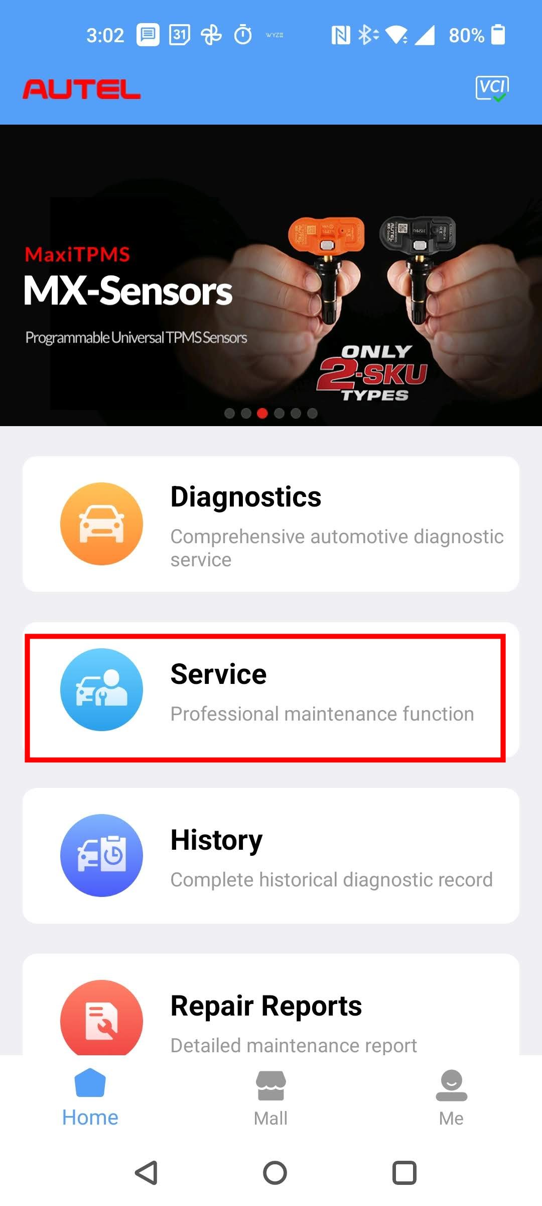
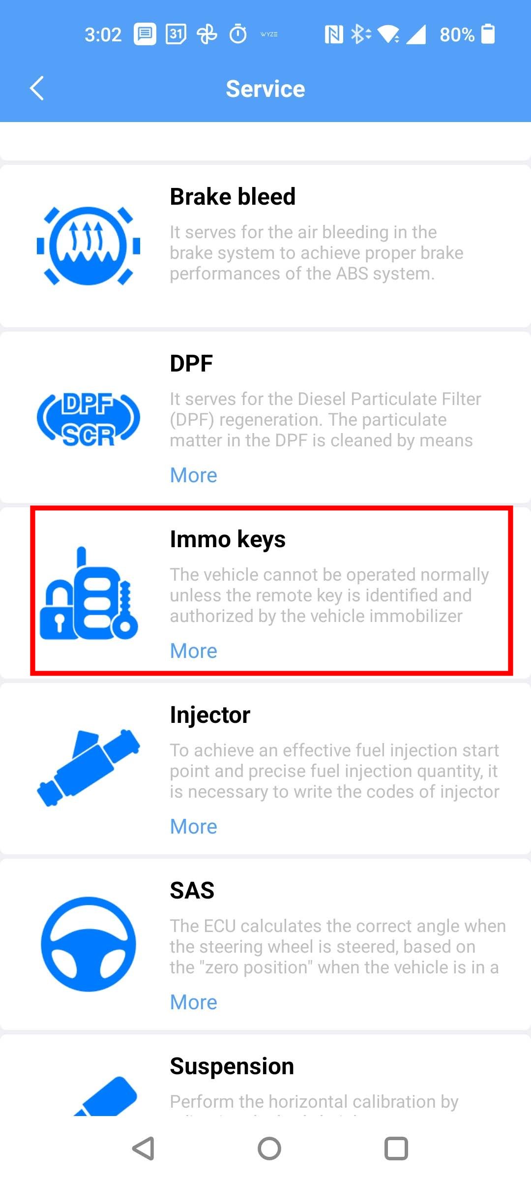
Launch the MaxiAP200 app on your phone, and select Service from the main menu.
Next, select the Immo Keys module:
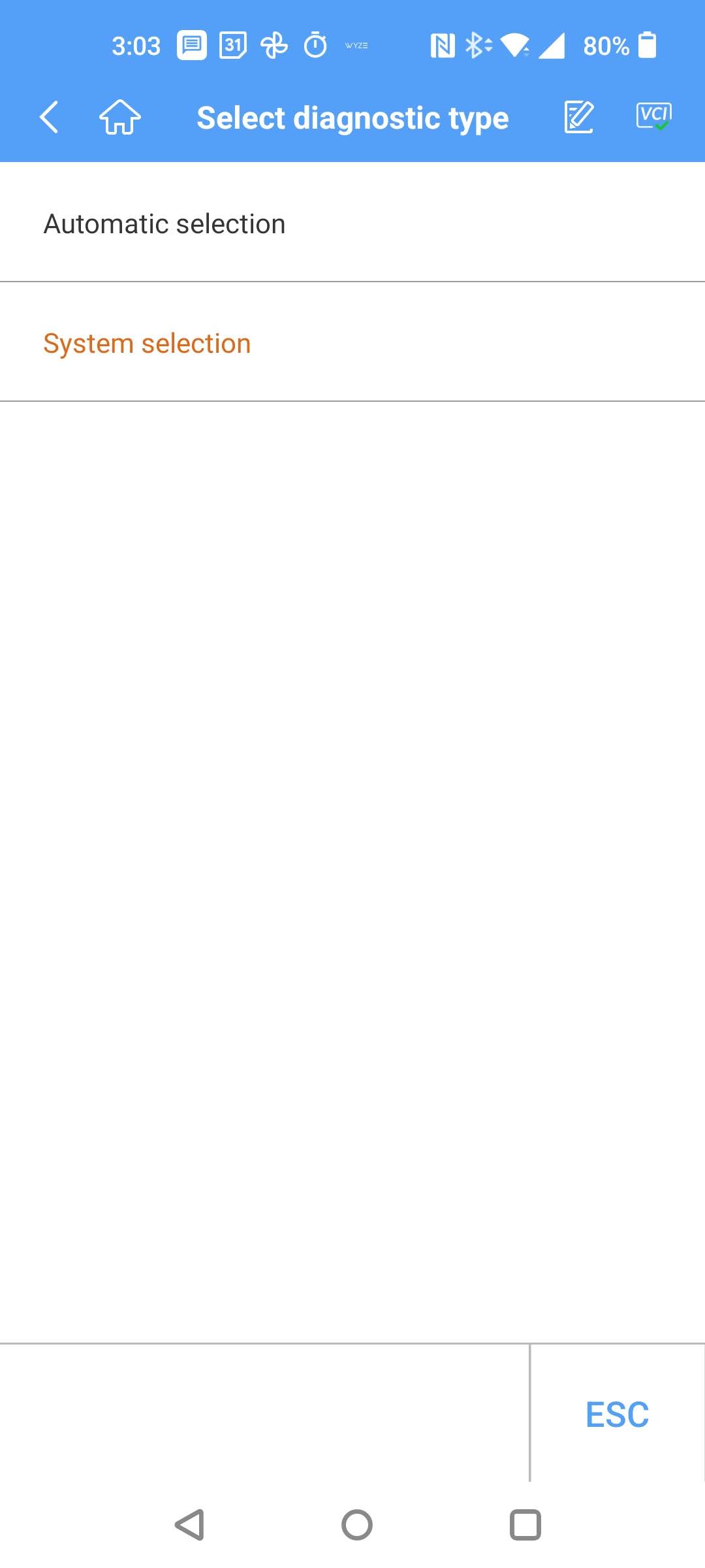
Then select your vehicle brand:
Next, you’ll be prompted to select the vehicle:
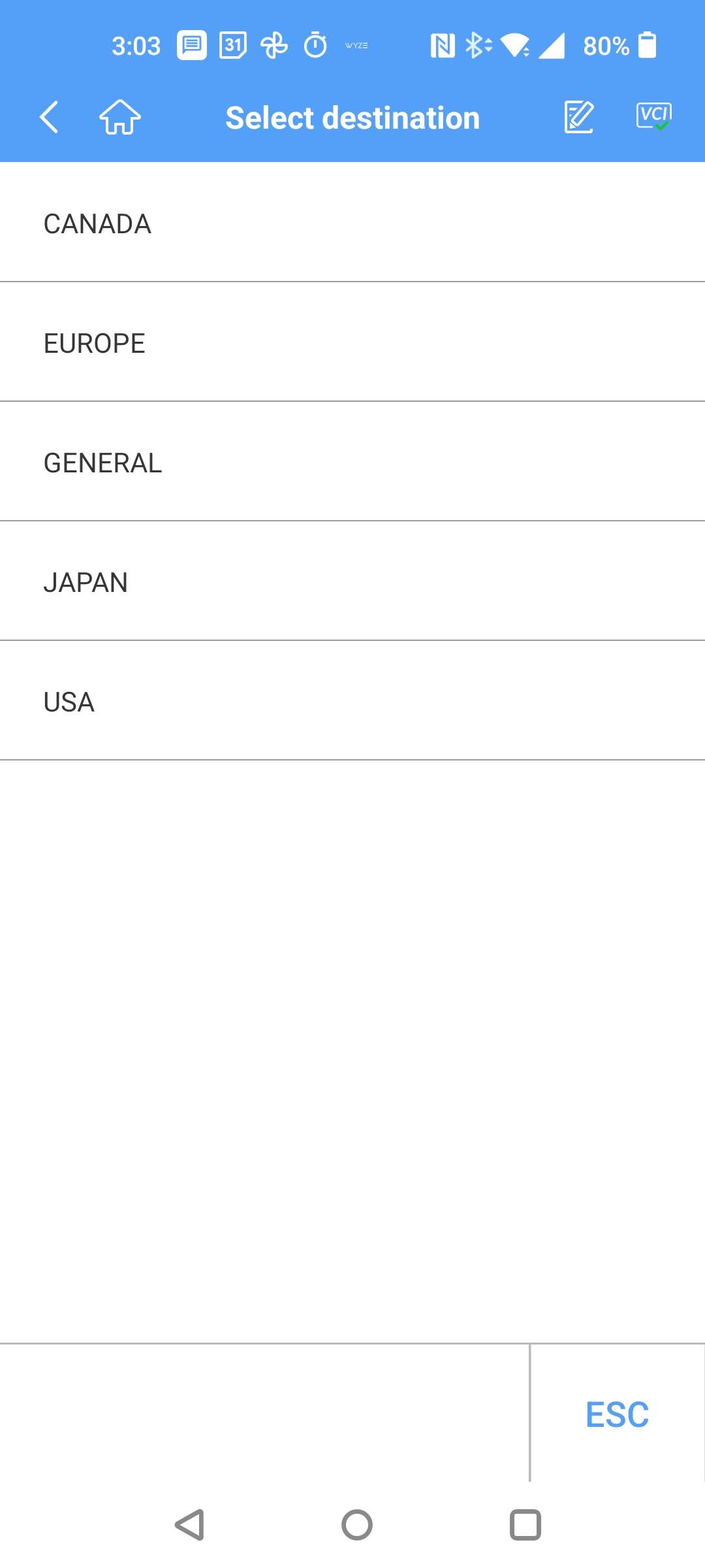
Then your vehicle’s country of sale:
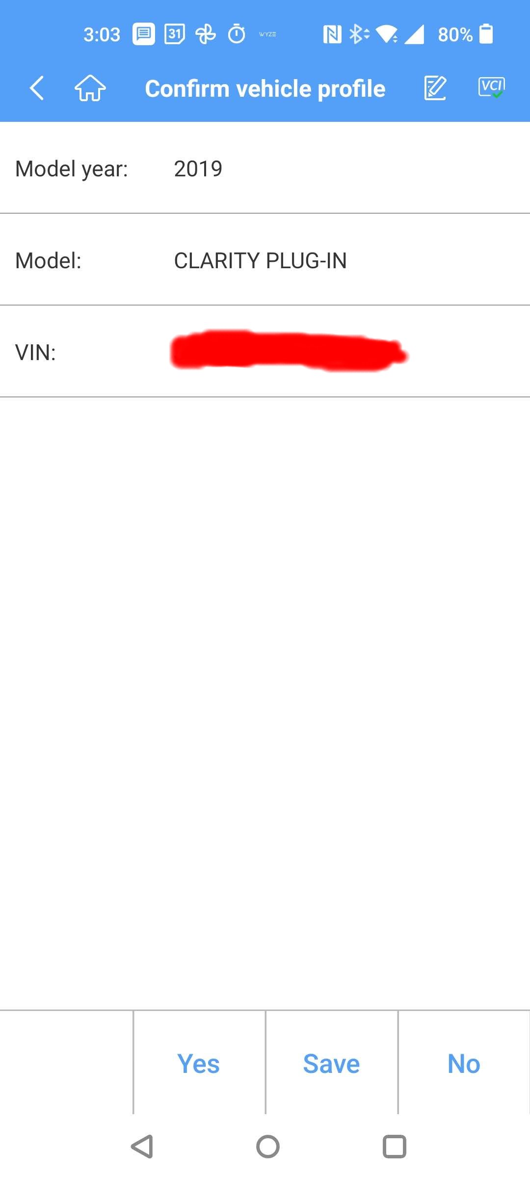
It will scan for your VIN, and then give you the following confirmation screen:
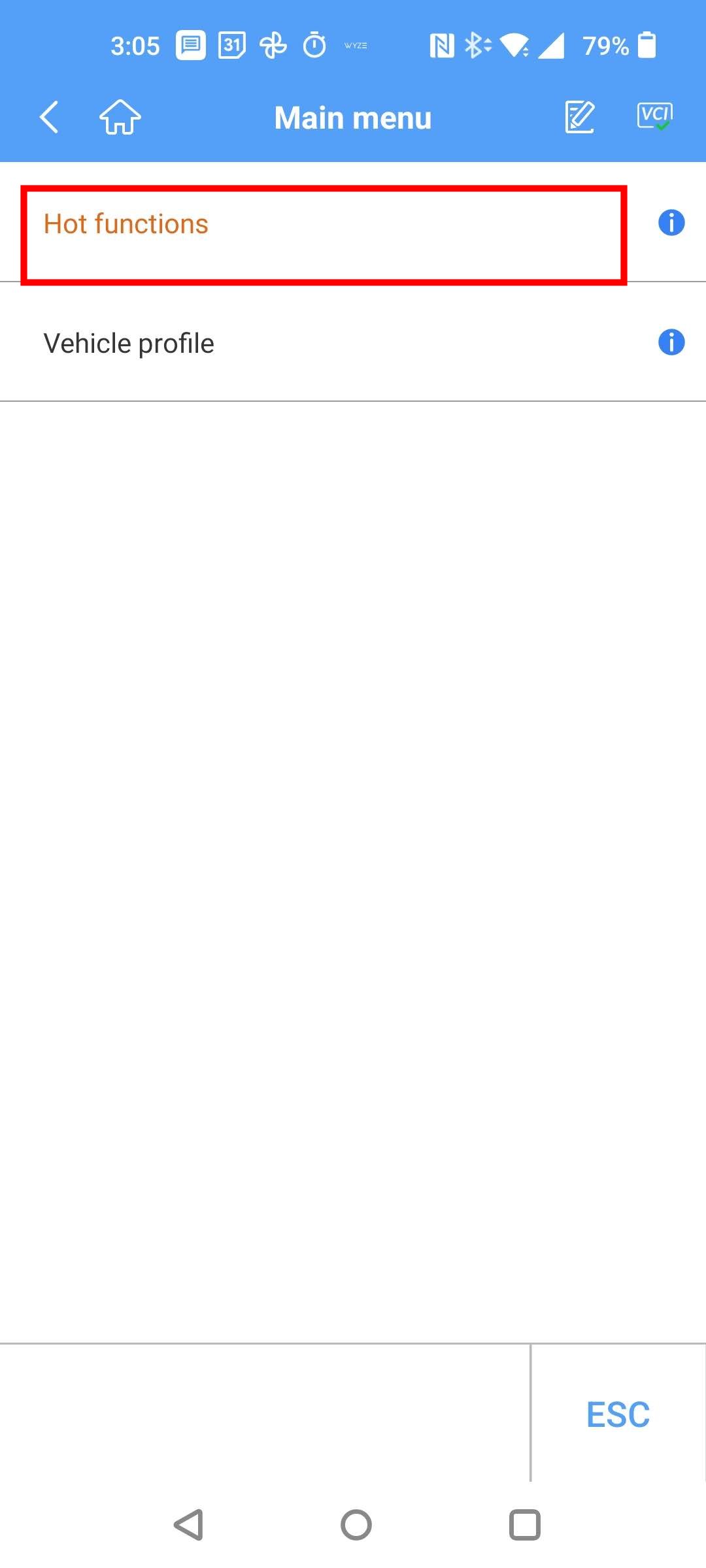
Next select Hot functions:
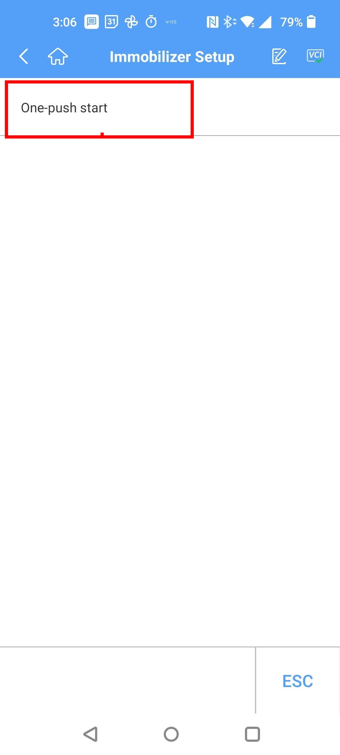
Tap One-push start:
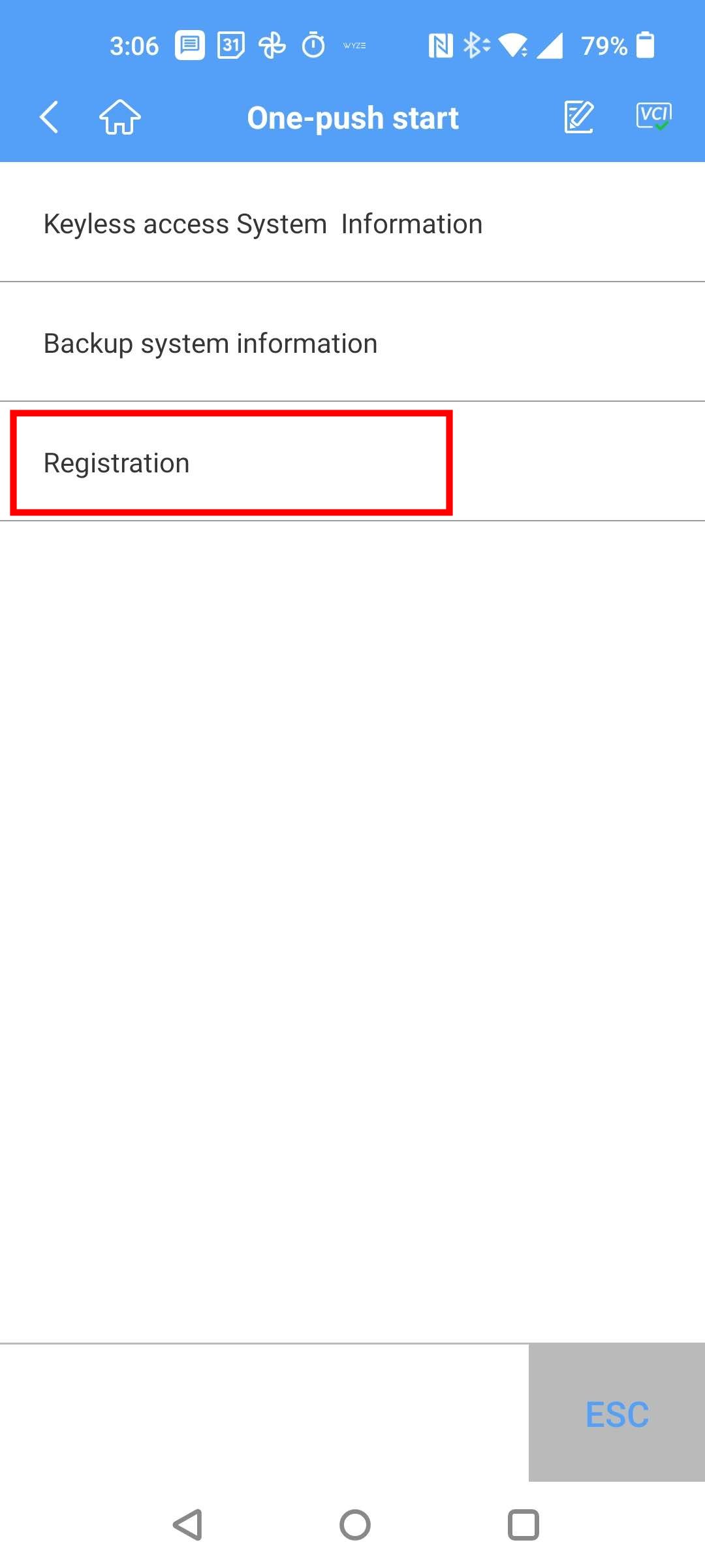
Tap Registration, which takes you to the functions for adding/removing fobs:
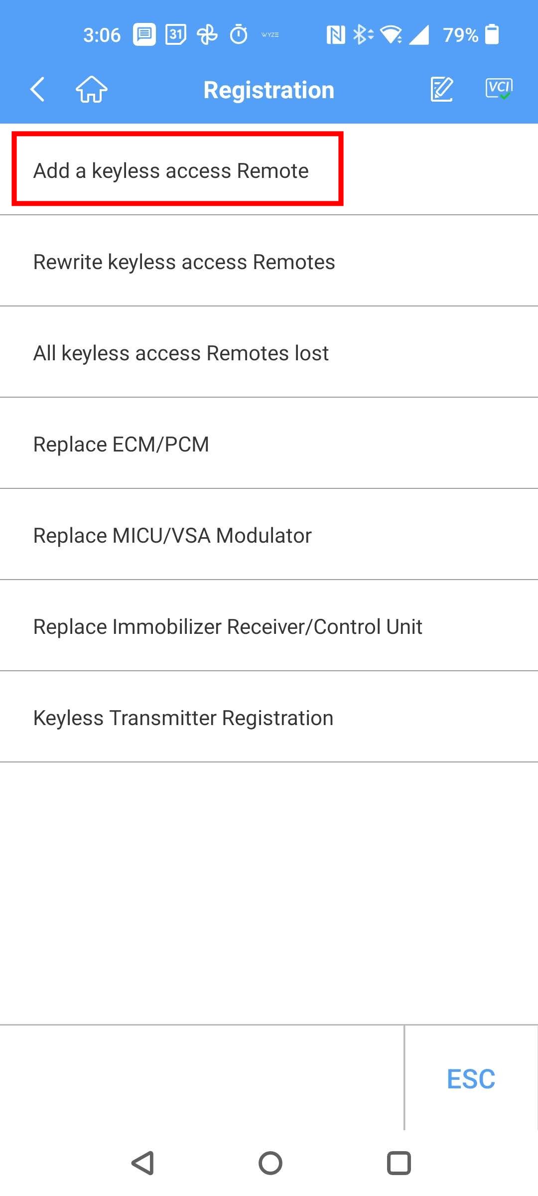
Select Add a keyless access Remote:
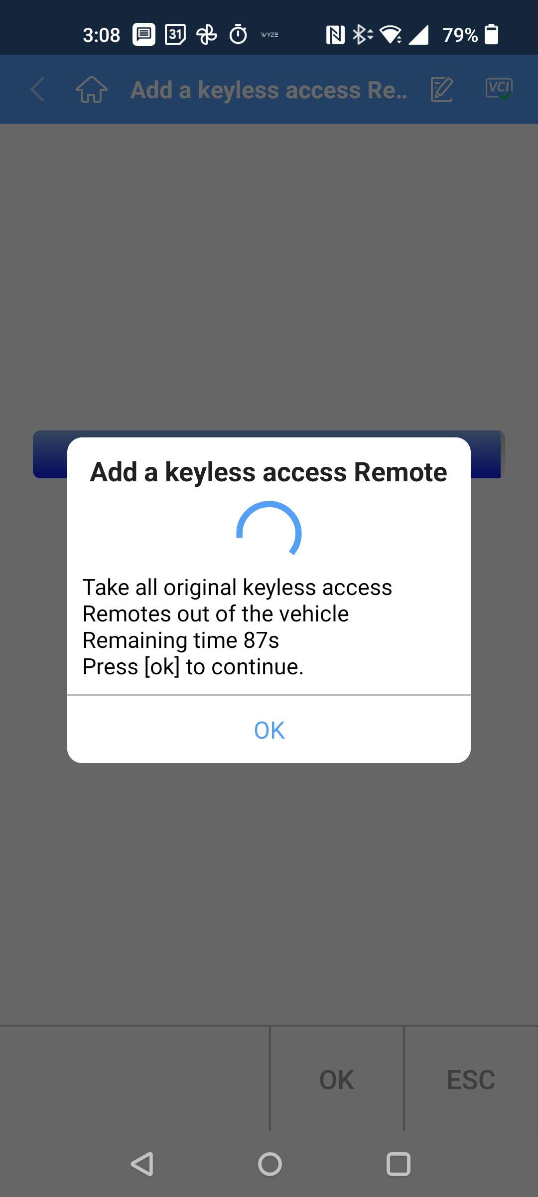
This launches you into the procedure for registering a new fob. Sorry, this is the part where I am missing some screens below. I can’t remember exactly, but it walks you through several steps.. pushing the car’s Start button w/ a working key fob in the vehicle, turning the car off, pushing the Start button w/ they fobs in and out of the car, etc. Just follow the prompts. I don’t remember the exact order. Below is one of the prompts:
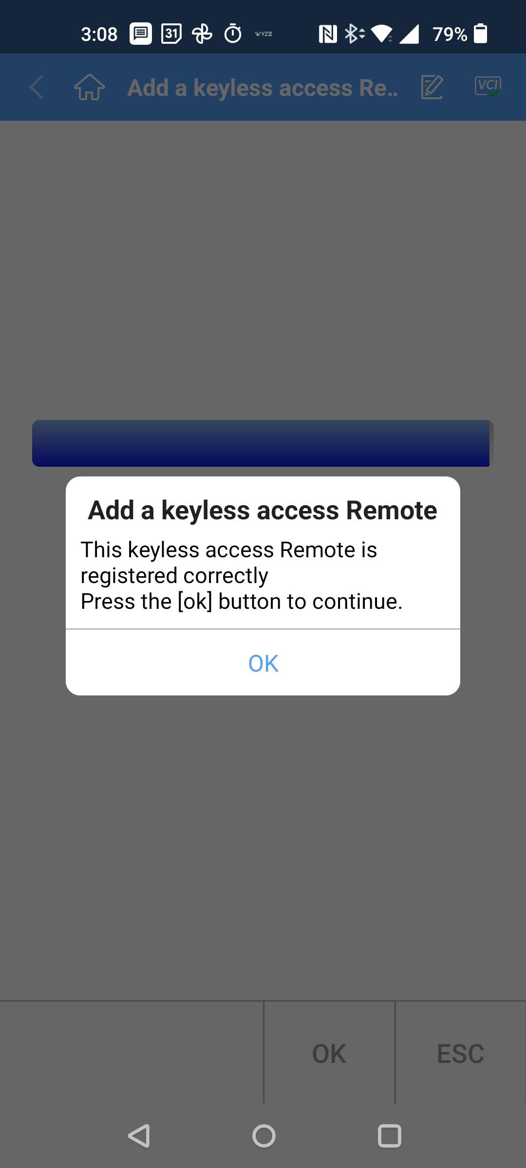
After you walk through all the steps, if you did everything correctly, you get this screen:
Now, the moment of truth! Try using your newly programmed fob to lock/unlock the doors, and start the car!
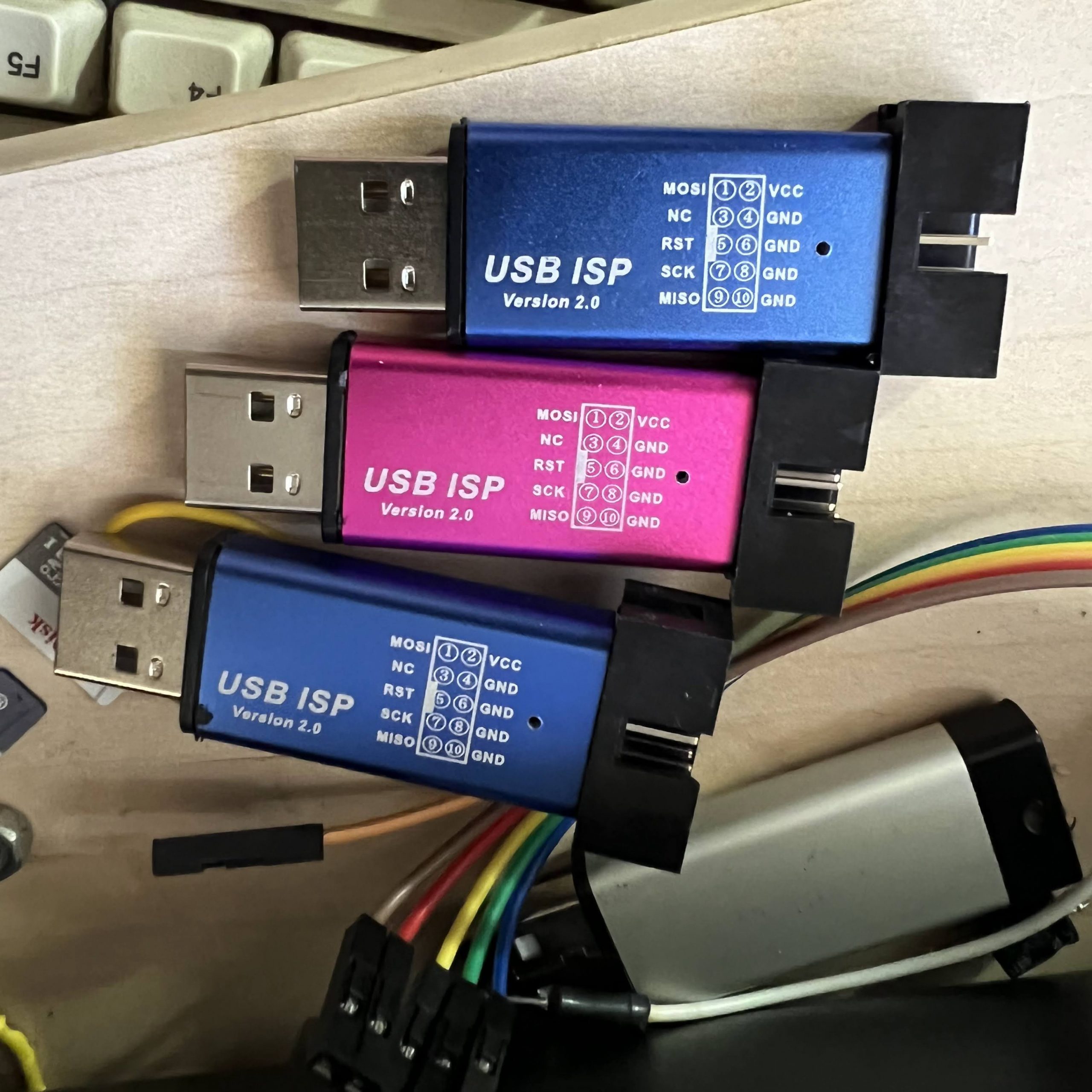
I recently ordered some USBasps from Amazon, which looked interesting, because unlike the typical USBasps, which are just bare PCBs, these had metal cases:
They are also common on AliExpress.
Unfortunately, when I plugged one into my computer, it detected as a USBHID device with VID=03EB and PID=C8B4, rather than as a USBasp. I tried overriding the USBHID driver on my Windows 10 machine, but that didn’t work.
Thankfully, after doing a bit of searching on the Internet, I found that others had encountered the same problem, and had found a solution. It seems that the firmware loaded into these things from the factory is proprietary, and require that you use the manufacturer’s janky software … it’s not AVRdude compatible!
Thankfully, the hardware is actually compatible w/ USBasp firmware with a minor tweak, and you just have to flash it with modified USBasp firmware.
I have a bunch of real USBasps, so I used a USBasp to convert the fakes into real USBasps! In order to program it, slide off the metal case. Next need to connect a jumper across the two holes labeled –> UP <–. The jumper enables programming of the onboard ATmega88V. Then plug it into your other USBasp or other ISP programmer, using the 10-pin ICSP cable:
So where do you get the special firmware? GreenPhotons has graciously compiled a modified firmware for us. Next use AVRdude to program the USBasp firmware into our target:
You can use any ISP you already have, if you don’t have another USBasp. Just substitute the programmer in the -c parameter (e.g. -cusbtiny for a USBtiny). If you don’t have another ISP programmer, you can use an Arduino. This guy shows you how, as well as another way to get firmware.
If you get the following error, then your USBHID ISP has an ATmega88P instead of an ATmega88V
D:\hacking\arduino\USBasp\convert_usbhid>avrdude -cusbasp -pm88  -Uflash:w:20161227_mega88_usbasp.hex

avrdude: AVR device initialized and ready to accept instructions

Reading | ################################################## | 100% 0.02s

avrdude: Device signature = 0x1e930f
avrdude: Expected signature for ATMEGA88 is 1E 93 0A
         Double check chip, or use -F to override this check.
Just substitute -pm88p for -pm88 in the avrdude command line:
20221212: Tapo Users, update from reader Roman below: The Tapo app on Android now has a software/firmware update that lets you reset the energy consumption from the app. Hopefully, iOS is the same.
20220914: Note: If you have an Apple device, you no longer have to use my laborious procedure documented below. The Watt for Smart Devices app can reset the energy and usage stats of both Kasa and Tapo devices.
WARNING: This method DOES NOT work the Tapo devices. They use an entirely different API. I wrote some code to try sending reset_energy_usage to a Tapo plug, but it rejected the command. If anyone knows the command to reset the energy usage of a Tapo, please leave a message below. Also, I might be able to find the correct command if someone can send me a firmware file for a Tapo plug with energy monitoring.
I recently acquired a few TP-Link Kasa KP115 smart plugs with energy metering. It was a bit disappointing to find that they barely show any data. There are no graphs, no voltage or current, just instantaneous power and summary energy stats and runtime:
I wanted to find the daily energy consumption of various appliances, so I needed a way to reset the energy counter to zero. Believe it or not, TP-Link doesn’t provide a way to reset the energy. TP-Link support says that you have to delete the plug from Kasa, factory reset, and then add it back to Kasa.
The most ridiculous part is, the smart plugs actually have a command to reset the energy without resetting the whole device! They’re just too lazy to add it to their app!
I found a github repo with a list of the commands available in the TP-Link protocol. It turns out that there’s a command to reset the energy monitor!
Erase All EMeter Statistics
{"emeter":{"erase_emeter_stat":null}}
The repo contains a Python3 script that can query the energy stats, but it doesn’t have an option to send the emeter reset command. Fortunately, it has a command line option to send an arbitrary JSON command to the plug. I tried sending the above to my KP115, and the energy meter was instantly reset to 0!
Next you need to know the IP address of the smart plug you want to reset. If you don’t know how to find it from your WiFi router, you can scan for it with an IP scanner, such as Fing. Look for a device named KP115 (or HS110).
In my previous article, HowTo: Upgrade Scosche Rhythm+ Firmware, I showed how to update Scosche Rhythm+ firmware via their Fitness Utility iOS app. Some people have had issues with the 3.01 firmware installed by the latest V2 Fitness Utility, notably incompatibility with certain apps, and/or flaky readings.
I contacted Scosche via live chat, and they told me that there was no way to downgrade from 3.01, except for sending the unit back to them. The V2 Fitness Utility no longer has a Firmware Update button, so there’s no way to use it to install any firmware other than v3.01. Instead of sending mine back to them, I decided to try to get a hold of an older version of Fitness Utility, in order to downgrade the firmware. It turned out to be a very laborious and time consuming procedure. I was hoping that I could share the IPA file of Fitness Utility 1.4.1 so everyone else could save a lot of time, but as reader Hap noted in the comments below, IPA files are tied to specific Apple IDs.
If you want to downgrade your firmware yourself, rather than send it back to Scosche, follow the rather lengthy and complicated procedure below.
To obtain the older version of Fitness Utility, I loosely followed the procedure from How to legally download any previous version of an App Store app through iTunes, but it was somewhat outdated, so I will summarize my own procedure below. I am not going to explain the nuts and bolts of what each step does, since that’s covered in the linked article.
Current versions of iTunes no longer support app installs, so you need to downgrade to an older version. The linked article states that there’s yet another hurdle, in that as of iTunes 12.5, Apple is using certificate pinning, which nullifies the ability of Fiddler to snoop HTTPS traffic. I tried an older version of iTunes, but it was no longer able to communicate with the App Store (Apple just LOVES to put up hurdle after hurdle for us!). After much searching, I discovered that in December 2017, Apple quietly released iTunes 12.6.3 for enterprise users who still need the ability to do app installs. Because it uses certificate pinning, I had to devise a procedure to get around that.
WARNING: THE PROCEDURE BELOW IS PROVIDED AS A RESULT OF MY OWN FINDINGS. THERE IS ABSOLUTELY NO WARRANTY, AND THERE IS A SMALL POSSIBILITY THAT YOUR DEVICE CAN BECOME BRICKED DURING A FIRMWARE UPDATE. MAKE SURE THAT YOUR DEVICE IS FULLY CHARGED BEFORE STARTING. IN FOLLOWING THE INSTRUCTIONS BELOW, YOU AGREE TO RELEASE ME FROM ALL LIABILITY, AND PROCEED AT YOUR OWN RISK.
How to download Fitness Utility 1.4.1 and use it to downgrade your Rhythm+ to firmware 2.62:
Find your current iTunes folder, and rename it to iTunes.sav, or just move it to a new location.On Windows 10, it’s located at C:\Users\<yourusername>\Music\iTunes. (Don’t worry, after you’re done, you can reinstall the latest iTunes, and restore your old iTunes folder).
Download and install Fiddler. DO NOT START FIDDLER YET
Launch iTunes 12.6.3 and download any random app. iTunes will prompt you to log in with your Apple ID. This is the loophole we use to get around the certificate pinning. It turns out that iTunes 12.6.3 only checks the certificate during the login process, and doesn’t detect when we later swap in Fiddler‘s fake root certificate so that it can snoop HTTPS traffic.
Before proceeding, it’s best to kill any programs on your computer that access the web, because they will pollute your Fiddler capture. If you have your web browser open in order to read this article, kill all of your other tabs that might be accessing the web in the background.
Launch Fiddler.
In Fiddler, go to the File menu and uncheck File->Capture Traffic
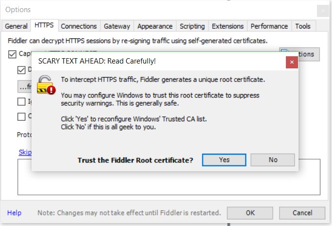
From the Fiddler menu, go to Tools->Options->HTTPS. Check the Capture HTTPS CONNECTs and Decrypt HTTPS traffic checkboxes. A dialog box will pop up asking if you want to Trust the Fiddler Root certificate. Select Yes to it, and all of the ensuing dialog boxes. Don’t worry, after we’re done, we will remove the fake certificate, and restore your original.
In Fiddler, go to the menu to check Rules->Automatic Breakpoints ->Before Requests
Launch iTunes and search for Fitness Utility in the App Store
In Fiddler, go to the File menu and check File->Capture Traffic
In iTunes, click the button to download Fitness Utility
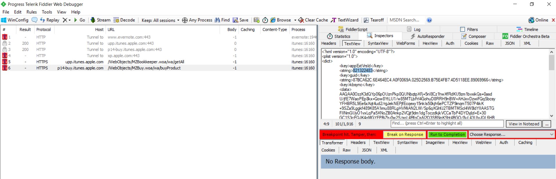
A few requests with red icons on the left will appear in the Fiddler capture pane. Select HTTP Tunnel to upp.itunes.apple.com:443 and click the green Run to Completion button in the right pane. Next, select HTTP Tunnel to p14-buy.itunes.apple.com:443 in the left pane, and click the green Run to Completion button in the right pane
A new request should appear in the Fiddler capture pane: HTTPS p14-buy.itunes.apple.com /WebObjects/MZBuy.woa/wa/buyProduct Select it in the capture pane, and then in the right pane, click the TextView tab, look for
In Fiddler, go to the menu to check Rules->Automatic Breakpoints ->Disable
Make sure the HTTPS p14-buy.itunes.apple.com /WebObjects/MZBuy.woa/wa/buyProduct request is selected in the Fiddler capture pane, and click the green Run to Completion button.
After iTunes shows that Fitness Utility is downloaded, verify that you have the Fitness Utility 1.4.1.ipa file in C:\Users\<yourusername>\Music\iTunes\iTunes Media\Mobile Applications
Connect your iOS device to your computer, and use iTunes 12.6.3 to install the Fitness Utility 1.4.1 to your iOS device, or use iFunBox instead as described below in Update 20170112
Launch Fitness Utility 1.4.1 on your iOS device and turn on your Rhythm+. WARNING: MAKE SURE YOUR RHYTHM+ IS FULLY CHARGED BEFORE UPGRADING THE FIRMWARE. IF IT DIES DURING A FIRMWARE UPGRADE, IT MAY BE RENDERED UNUSABLE.
Tap the Commands button at the top right of the screen, and then tap the Start button next to Firmware Update.
After the update is completed, power cycle your Rhythm+
You can check that the firmware version is now 2.62 by tapping the Attributes button at the top left of Fitness Utility.
VERY IMPORTANT: Once you verify proper operation of Fitness Utility, on your computer, have Fiddler restore your original root certificate with Tools->Options->HTTPS->Actions->Reset All Certificates.
Copy your Fitness Utility 1.4.1.ipa file somewhere so that you can reuse it in the future if you wish.
Delete the new iTunes folder, restore your old iTunes folder by renaming iTunes.sav to iTunes, uninstall iTunes 12.6.3, and reinstall your original version of iTunes.
Now that you have your own copy of Fitness Utility 1.4.1.ipa, you are free to try any future firmware upgrades from Scosche, because it’s easy to go back to a working version if you don’t like the new one. If you use iFunBox, you don’t even have to mess with swapping out iTunes versions.
If you prefer to downgrade to firmware v2.4, you can use Fitness Utility 1.4.1 and follow the procedure below:
*** WARNING: DOWNGRADING TO FIRMWARE V2.4 DISABLES THE ABILITY TO UPDATE FIRMWARE VIA FITNESS UTILITY. IF YOU LATER CHANGE YOUR MIND, AND WANT TO INSTALL A DIFFERENT VERSION, YOU WILL HAVE TO SEND THE UNIT BACK TO SCOSCHE. ***
send the unzipped HEX file to an e-mail address accessible from your iOS device
open the e-mail you sent on your iOS device, tap the attachment, and then scroll through the on screen icons until you find Copy to Fitness Utility, and tap the icon.
Turn on your Rhythm+ and follow steps 19-22 above.
The above method actually works with any version of firmware HEX file that you are able to obtain.
Update 20180112: I tried installing Fitness Utility 1.4.1.ipa with iFunBox instead of iTunes, and it also works. Launch iFunBox with your phone connected to your computer, and install the app by clicking the Install App(*.ipa) from the main screen. Firmware 2.4: scosche-rhythmplus-2_4.zip
Typically, OpenEVSE firmwares are flashed into the board using a hardware programmer, such as a USBasp. In the past, this was required, because the firmware had grown so large that there was no space left in the ATMega328P‘s flash to fit in a bootloader. However, the latest versions of the AVR tools that come with Arduino have shrunken down the binaries to the point that we now have space for a bootloader. Once the bootloader is installed, OpenEVSE can be programmed in exactly the same fashion as an Arduino Pro Mini, via a USB->TTL UART adapter, such as a FTDI cable, using the stk500 (arduino) protocol.
Before we can program the chip with a bootloader, we need to make a minor hardware mod. After a reset, the bootloader waits to see if a new firmware wants to be flashed before proceeding with booting the installed firmware. It is only during this very small time window that the ATMega328P‘s MCU is ready to accept a firmware. In order to trigger a reset via software, we need to connect the DTR pin of the FTDI cable to the RESET pin of the MCU via a .1uF capacitor.
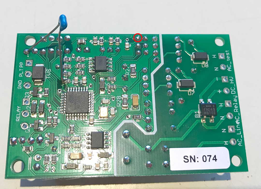
Below is a photo of the mod, done on a Wattzilla C3 board, which is an OpenEVSE variant:
The DTR pin is on the far left of the 6-pin serial connector. The RESET pin can be accessed at either the left side of R10, as pictured above, or at Pin 5 of the ISP connector (red circle).
Once the hardware mod is in place, we must set the fuses to use a bootloader, and flash in the bootloader, using a hardware programmer. In this example, we will use OptiBoot, because it’s smaller and faster (115200 baud) than the standard Arduino bootloader.
Substitute your FTDI cable’s virtual serial port for COM5 above.
For those who are not comfortable with command lines, it’s also possible to use the Arduino IDE to burn the bootloader, and flash in firmwares.
Set your board to Arduino UNO by using the menu to navigate to Tools->Board->Arduino UNO
Select your hardware programmer via Tools->Programmer
Install the bootloader via Tools->Burn Bootloader
Disconnect the hardware programmer, and use Tools->Port to select your FTDI cable’s virtual serial port.
Thereafter, you may flash in your sketches with the upload button. The above procedure will also work with any DIY or other Arduino clone which is not wired for a bootloader. Note that the bootloader takes up 512 bytes, so your maximum sketch size drops from 32768 to 32256 bytes.
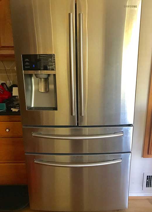
I have a Samsung RF28HMEDBSR french door refrigerator that’s only a few years old.
Several months ago, I started to notice a mild clicking sound coming from it occasionally. The sound would always stop as soon as I opened the door, and then usually restart a little while after closing the door. In the past few days, the noise got considerably louder. It became clear that the sound was coming from a fan that was inside the refrigerator compartment. It started sounding like a fan whose blades were hitting something. Then this morning, it became unbearably loud.. like there was an airplane inside my kitchen!
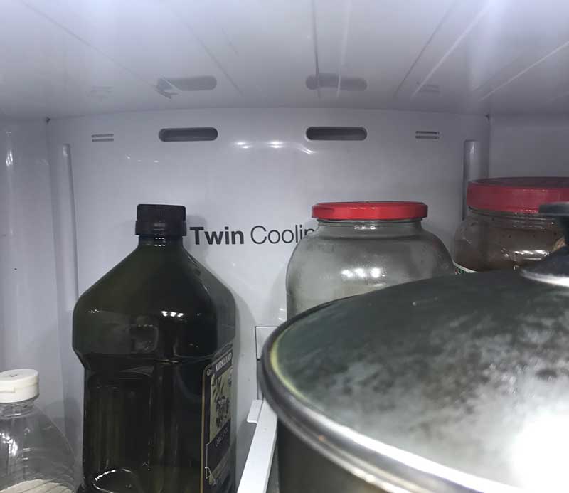
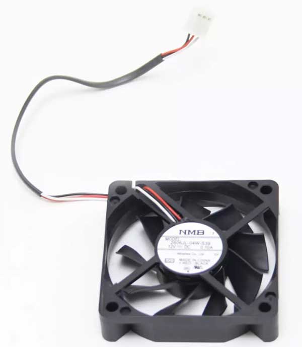
I thought maybe the fan bearings were just dry and needed oil. After doing a lot of research on the Internet, I figured out that the evaporator fan, which circulates cool air inside the refrigerator, was probably the culprit. It turns out that ice builds up on the evaporator (due to bad design of the defrost circuit), and eventually hits the fan blades, causing the racket. The evaporator fan is a box fan that’s attached to the evaporator cover in the back of the fridge, behind where it says Twin Cooling:
The fan looks like this:
The proper fix is to remove everything from the refrigerator, take out all the drawers and shelves, remove the evaporator cover, and then melt the ice. I didn’t have time to do this today, and just wanted to silence the racket, so I decided to try a quick hack. The ice build up usually occurs on the coolant pipes feeding the evaporator. Notice how there are two large oblong air holes in the evaporator cover (see above photo), above Twin Cooling. The coolant pipes are approximately behind the air slot on the right.
I decided to try blowing hot air into the air slots, to melt some of the ice enough so that it wouldn’t hit the fan anymore. It’s important not to blow air that’s so hot that it melts the plastic cover. I set my dryer to high, and then pointed it at my hand, adjusting the distance so that the air was just a little too hot for me to tolerate. Then I aimed it at the intake slots, at about the same distance, and alternated blowing air into them, 10 seconds at a time, for 2 minutes:
Voila! The noise is completely gone! When I have more time, I will do the proper fix, taking the evaporator cover off, and melt the ice that’s covering the evaporator. Most likely, there’s a lot of ice back there, which blocks air flow to the evaporator, reducing the efficiency of the refrigerator, which wastes electricity, and in the worst case, keeps it from cooling properly. I will make a post in the future, documenting the process as I go.
In the meantime, if you want to tackle the proper fix yourself, here are some YouTube videos which are helpful:
At about 4:35 in the video above, the guy has a good hack for preventing the issue from ever happening again. He moves the temperature sensor for defrosting from the inlet to the outlet pipe of the evaporator, which extends the defrost cycle.
UPDATE 2020-05-20: It’s been almost 3 years since I applied the temperature sensor moving hack described above, and I haven’t had a recurrence of the noisy fan, so it works well as a permanent fix!
The video below gives a lot more details on disassembly procedures:
AVRDUDE has a little-known command line parameter, -B, which sets the bitclock, and can dramatically speed up writing/reading firmware to/from an AVR MCU when using a USBasp or USBtinyISP. For a USBasp, simply add -B0.5 to your command line parameters. Example:
In my tests, adding -B0.5 reduces the time to write & verify a hex file by about 2/3! For the USBtinyISP, add -B1 to your command line parameters. Example:
The speedup is even more dramatic with the USBtinyISP. In a specific test, I found that write/verify time dropped from 59 sec to 17 sec!
You can also speed up programming from the Arduino GUI. Simply edit your programmers.txt file. In older versions of Arduino, it can be found in <ArduinoFolder>/hardware/arduino/avr/boards.txt. For Arduino 1.8.x, it’s located in C:\Users\<YourUserName>\AppData\Local\Arduino15\packages\arduino\hardware\avr\<version>\programmers.txt.
For the USBasp, add the -B0.5 parameter to the usbasp.program.extra_params line:
usbasp.program.extra_params=-Pusb -B0.5
In order to realize the speed gain in programming, the USBasp must have firmware which supports the setting of SCK. If AVRDUDE gives you this warning:
avrdude: warning: cannot set sck period. please check for usbasp firmware update.
For wireless control of WS2812B (NeoPixel) LEDs, I initially played with Bluetooth SPP (Serial Port Profile), due to the simplicity of setting up the host software… from the host’s software’s point of view, the connection just looks like a physical serial port. Unfortunately, the flakiness of my Windows 8.1 PCs’ Bluetooth SPP support caused me to abandon that solution.
WIFI CONTROLLER HARDWARE
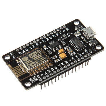
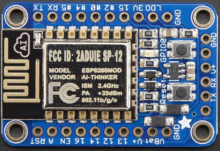
ESP8266 modules provide a very low cost method of interfacing WS2812Bs to WiFi. Adafruit’s Huzzah module costs $9.95, but on eBay, NodeMCU clones, such as the LoLin NodeMCU board can be had for ~$3 shipped from China. This makes it even cheaper than the Arduino/Bluetooth combination!
What’s more, the LoLin board has a CH340G onboard, so it doesn’t require a FTDI cable to connect it to your host computer for programming. I ordered a few of the LoLin boards, but in the meantime, I started playing with the Adafruit Huzzah boards I had on hand.
With the addition of ESP8266 support via the Board Manager, Arduino becomes an easy to use platform for code development. Also, there are easily obtainable libraries for both WiFi configuration and control of the WS2812Bs.
One extra complexity of using an ESP8266 to control WS2812Bs is that the ESP8266 is a 3.3V device, while the WS2812B is a 5V device, (usually) necessitating level shifting. The WS2812B datasheet shows a threshold of >= 0.7VDD for logic HIGH, and <= 0.3VDD for logic LOW. The allowed VDD ranges from +3.5-5.3V. Interestingly, some WS2812Bs can actually work when powered by 3.3V, and driven by 3.3V logic, even though it’s out of spec, but many cannot. On the other hand, it’s totally within spec to be powered by 3.7V and driven by 3.3V logic. So, if you use a 3.7V LiPo battery to power the WS2812B strand, the WS2812B data line can be connected directly to the ESP8266 without any level shifting! If you choose to go this route, power the Huzzah from its VBat terminal, so that the 3.7V will be regulated down to 3.3V to power the ESP8266. More details are available in Adafruit’s NeoPixel Uber Guide.
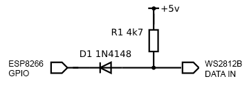
Since I want to be able to drive long strands of LEDs, I elected to go the 5V power with level shifter route. Also, I have lots of 5V power supplies laying around. There are many different ways to do level shifting, either passive or active. The WS2812B has tight timing requirements, and runs at 800KHz, so care has to be taken in order to avoid signal distortion. One of the most reliable methods is to use a 74AHCT125 level shifter IC. I decided to first try a simple diode and pullup resistor circuit (credit: RPi GPIO Interface Circuits):
The circuit is currently working flawlessly for me, driving my 5m long strand of 150 LEDs.
WIFI COMMUNICATION PROTOCOL
In order to send data to our WS2812Bs over WiFi, we need some sort of IP protocol. Art-Net is a royalty-free protocol, which sends DMX data embedded in UDP packets. I decided to go with Art-Net because it is an industry standard that is supported by a variety of Pro software, and Jinx! and Glediator can talk to it.
ARDUINO FIRMWARE
I will not go into how to set up Arduino to compile sketches for the ESP8266, as that is discussed elsewhere. To compile for the Huzzah, select it as the compile target from the Tools pulldown menu:
Tools -> Board -> Adafruit HUZZAH ESP8266
I created a sketch, which is a mashup of a few different projects from github. The code is in my github repo: WS2812ArtNet. I stripped the Adafruit NeoPixel library down to the bare metal, and added a captive portal for configuring the WiFi connection. Also, it supports a hardware pin to erase the WiFi settings. Configuration is done via a few defines in WS2812ArtNet.ino. See the #defines for PIXEL_CNT, PIN_DATA, PIN_LED, and PIN_FACTORY_RESET. At a minimum, PIXEL_CNT must be set to the number of LEDs in your strand.
PIN_DATA is used to select the pin that’s used to drive the data to the LED strand.
PIN_LED is used to select the a pin which blinks an LED every time an Art-Net packet is received. This makes it easy to tell if the board is receiving data. In addition, the LED is initially off at boot-up, and turns solid red when the ESP8266 connects successfully to a WiFi AP. By default, PIN_LED = 0, which makes it control the onboard red LED on the Huzzah.
PIN_FACTORY_RESET wipes out any saved settings and clears the EEPROM when it’s grounded for 2 sec.
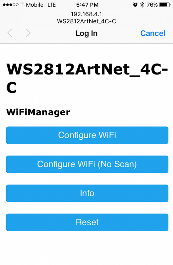
To load the WS2812ArtNet sketch into the ESP8266, first press the GPIO0 and Reset buttons simultaneously, and then let go of the Reset button. The red LED will then glow dimly, indicating that the bootloader is active. Once the sketch is loaded, when the ESP8266 initially boots up, it will create a WiFi AP with SSID WS2812ArtNet_hh-h. Use a computer, phone, etc to connect to the AP. Upon connection, it should automatically present a captive portal for configuration:
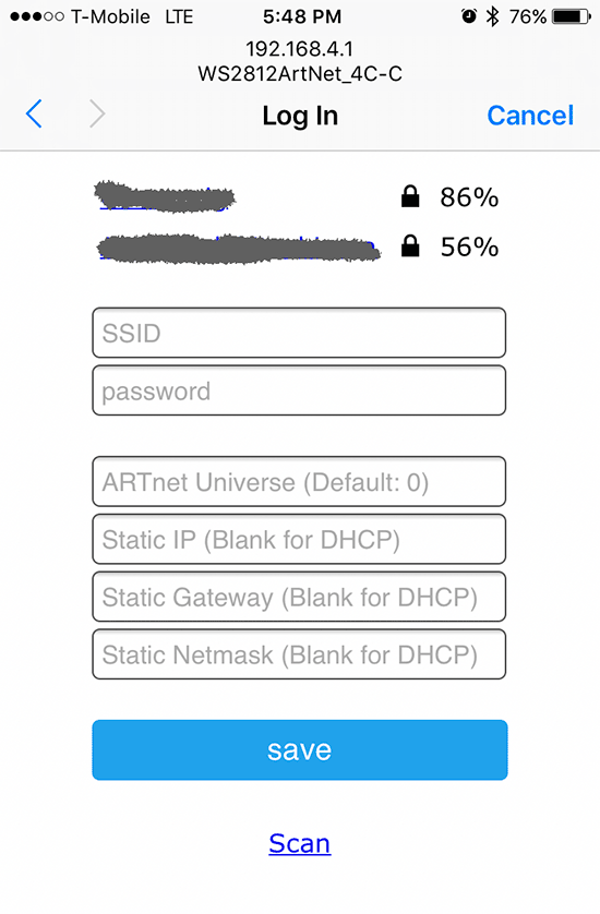
If the captive portal doesn’t automatically launch, open a web browser, and point it to http://192.168.4.1. Tap on Configure WiFi, and the ESP8266 will automatically scan for available APs:
Tap the desired AP’s SSID, and type in the passphrase. Additionally, you can also choose a starting Art-Net universe, and configure a static IP. After you tap save, the ESP8266 will reboot. If it connects successfully to your AP, the onboard red LED will light. Then, the LED strand will go into the startup test sequence of lighting up red, green, and blue, and then turning off. Once Art-Net data is received, the LED still start blinking with every packet it receives. If you have trouble during setup, you can see debug messages by opening the ESP8266’s serial port in a terminal set to 115200,N,8,1.
When configuring Jinx!/Glediator, select GRB as the pixel data format.