RepRap – 3D Printing Project Kickoff – Printrboard First Look

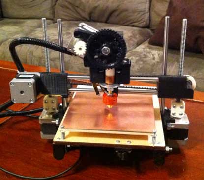
I have been somewhat intrigued by the RepRap project, an open source 3D printer movement, for several years.  However, wasn’t motivated enough to jump into the fray until late last year, when I saw Brook Drumm’s Printrbot on Kickstarter.

With only about 1 hour left before funding closed, I pledged $500 to get a Printrbot kit. While I could have started from scratch, and built a Prusa Mendel, after reading about how much tweaking is involved in building and setting up a RepRap, I decided to start with a Printrbot – a cute, compact, and simple design, and the most inexpensive RepRap at the time.  Printrbot’s Kickstarter was a smashing success.  They raised an astonishing $830K. Unfortunately, the gigantic amount of orders they received means that mine will take a little longer to get to me than I originally anticipated. So, I’ve been immersing myself in the intricacies of the electronics, firmware, host software, and mechanical aspects of RepRap for the past couple of months.

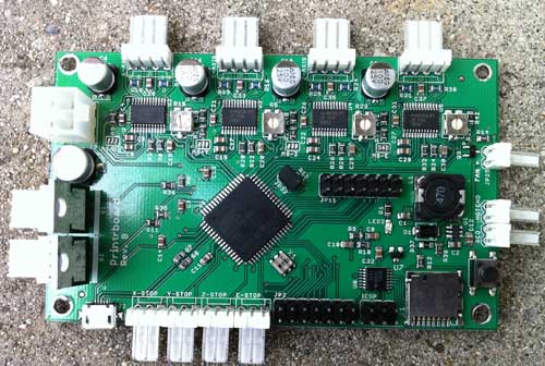
There are a variety of popular controller electronics for RepRap, the most popular being RAMPS.  The electronics are one of the largest costs of building a RepRap.  Although RAMPS is convenient, because it’s based on an Arduino Mega, I like the idea of having a single dedicated board.  The Printrbot folks have designed their own controller board, which they call Printrboard.  Although Printrbot is not yet selling Printrboards, the design is open source, and thus, I was able to obtain one before their release.

Kang, a fellow RepRapper from Seoul, Korea, built a few Printrboards and sent me one to play with.

Printrboard is a fork of Teensylu, an AT90USB1286/AT90USB1287 based RepRap controller.  I like the fact that these boards are based on the AT90USB128x MCU’s because they have built-in full USB support, eliminating the need for an external serial->USB bridge IC; additionally, the native USB support means that communication with the host computer is blazingly fast – 12Mbps rather than 115200kbps.

There are a few notable differences between Printrboard and Teensylu.  Printrboard is a single board solution.  First, Printrboard adds an integrated SD card reader.  This is handy for printing while untethered to a computer.  Teensylu has I/O pins which can be used to easily add an SD card reader.

Second, the stepper motor drivers are integrated onto Printrboard’s PCB, while Teensylu uses plug-in Pololu/Stepstick carriers.  The advantages of integrating the stepper drivers onto the main PCB are reduced cost and compactness.  The downside is that it is not uncommon to blow up a stepper driver IC, so having them soldered in means if one goes bad, the whole board is unusable.

Third, Printrboard uses Allegro A4982’s in a 24-TSSOP package, while Pololu/Stepstick use the Allegro A4988 in a 28QFN package.  The TSSOP package is considerably larger, and has a wider pin pitch, which makes reworking the board easier if one of them blows out; the 28QFN is very tiny and not for the faint of heart.  The other difference between the A4982 and A4988 is that the A4982 only supports full/half/quarter/sixteenth stepping, while the A4988 also supports one eighth stepping.

Some other minor differences between Printrboard and Teensylu are that while Printrboard only supports a 12V2 ATX power input, Teensylu gives more power options.  Also, Teensylu has a large USB-A socket, while Printrboard uses a micro USB-B socket.

I am diving into figuring out how to load Marlin RepRap firmware into Printrboard/Teensylu, to keep my end of the bargain with Kang.  A series of articles will follow with my findings.
OpenEVSE – Open Source J1772 EVSE (“Charging Station”) for Electric Vehicles

Last year, I purchased a Nissan Leaf, which is an all electric vehicle (EV). Although the Leaf comes with an included L1 EVSE (“trickle charger”), which connects to a regular 120V wall outlet, it takes way too long to charge the car. The more practical solution is to purchase and install a J1772 L2 EVSE which is equivalent to the commercial charging stations you see in public parking lots. The problem is the cost. J1772 L2 EVSE’s cost a couple of thousand dollars; the quote I got from Aerovironment, Nissan’s chosen installer was about $4000 including installation. Considering that modern EV’s using the J1772 standard have the charger built-in to the car, and that a J1772 EVSE is no more than a smart safety interlock plug for connecting the car to the wall, I thought the cost was pretty outrageous.

I obtained a copy of the SAE J1772-2010 standard, and after a few hours of perusing it, realized that a J1772 EVSE could be implemented with an Arduino, a few parts, and a relay at the fraction of the cost of the commercial products.  Furthermore, that the circuitry is so simple and compact that it could be built into a small case that fits into your hand, and can easily be thrown into your trunk, rather than the giant monstrosities like GE’s WattStation.

I started to design my own EVSE around an AVR MCU, but soon discovered that Chris Howell had had exactly the same idea, and posted about his Weekend EVSE project on the MyNissanLeaf forums.  Chris had already made major progress on the project, so I thought, why reinvent the wheel?  I contacted Chris, and we decided to team up to develop an inexpensive, portable L1/L2 J1772 EVSE. Chris is a wizard with PCB layout, and has shrunken the board down to smaller than an Arduino over several revisions. It’s truly a sight to behold how tiny and simple it is after seeing the giant messy hackorama that’s being funded by the DOE, the $5000 Blink EVSE, which is just an amalgam of OFF THE SHELF DEVICES IN THEIR ORIGINAL CASES: http://www.mynissanleaf.com/viewtopic.php?f=26&t=5664 . One thing that I find annoying about commercial EVSE’s is that they often waste too much power in standby mode. Nissan’s included EVSE draws about 3W in standby, which doesn’t sound like much, but the question is WHY? Vampire power wastes about 10% of the energy used by a typical residential household. I’ve heard that the Blink wastes more than 50W when it’s doing nothing. Not only that, many of the commercial offerings (including Nissan’s included L1 EVSE) aren’t even 100% J1772 compliant!

After many hours of tweaking and testing, we designed a 100% J1772 compliant dual mode L1/L2 EVSE.
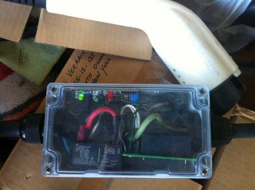
This DIY EVSE has worked flawlessly charging my Leaf ever since last summer:

The actual EVSE logic board is the tiny PCB at the top with the 3 LED’s attached to it.  The switching power supply is on the bottom right, and a 30A relay is on the bottom left.  A CT in the upper right is used to detect ground faults.

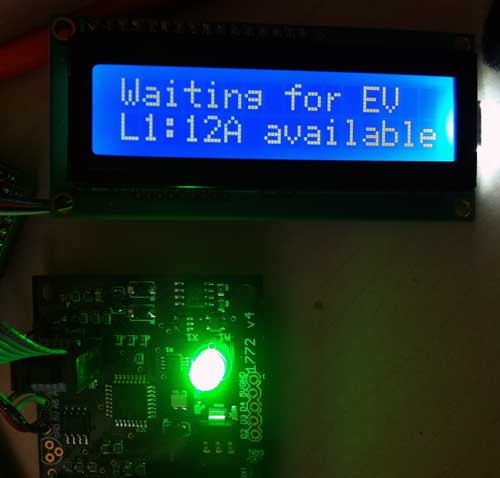
For a portable unit to throw in my trunk, I need adjustable current, so I’ve implemented a 1-button menu interface using a common HD44780-compatible 16×2 LCD, connected to an Adafruit LCD backpack, which greatly reduces the pin count required for interfacing to it. I’m currently using it in i2c mode.

Note how small the controller PCB is now … Chris is a PCB layout ninja … yes, that’s a complete implementation of a J1772 EVSE on that tiny board.  Now, go back to the Blink EVSE link I listed above, and see how huge and complex the circuits are in the commercial offerings THAT AREN’T EVEN 100% compliant to the standard!

This time, instead of going into the expensive box I bought for the first EVSE, it’s going to live in a $5 NEMA wiring box from my local hardware store. I think this box will be a lot more durable against getting dropped and thrown around than my fancy $18 NEMA box.

Hardware hackers, what are you waiting for?  Join in on the fun.  We’ve open sourced the design as OpenEVSE:  http://code.google.com/p/open-evse/. Now, you can build your own fully hackable, customizable EVSE!

DISCLAIMER:  Don’t jump into this project unless you have a thorough understanding of the precautions which must be taken when dealing with high voltages and currents.  It’s quite easy to electrocute yourself and DIE if you don’t know what you’re doing.

AVR CAN Bus Project: Step 4 – LeafCAN: Nissan Leaf SOC Meter

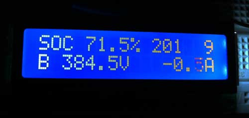
I have implemented a SOC (State of Charge) meter for the Nissan Leaf. Many thanks to garygid and others from the MyNissanLeaf forums, for their help in decoding the Leaf CAN bus messages, and figuring out the pinouts.

The top line shows the SOC%, raw SOC value, and number of charge bars displayed in the dash.
The second line shows battery pack voltage and current in amps.

You can download the Eagle CAD schematic and AVR (Arduino) code from github:  lincomatic / LeafCAN
The Eagle schematic uses the Sparkfun library.

The schematic shows how to implement the entire circuit, without using the Olimex AT90CAN128 breakout board.

My original intent was to make a small PCB that directly attached to the LCD, and put it into a small case, but I never got it past the breadboard stage.  Unfortunately, I have gotten busy with other projects, so I am probably not going to do further development on this device nor finish the PCB layout, unless there is a large amount of interest. However, feel free to adapt it as you wish for your own CAN bus projects. Do bear in mind, however, that the design is licensed via the GPL, so if you use it for a commercial project, you must openly share your design.

Previous: AVR CAN Bus Project – Step 3: CANspy CAN Bus Monitor
Next: LeafCAN v1.1 Released