ITEAD Studio IBOX – Part 1: First Look

ITEAD Studio recently contacted me to let me know that they’re going to display my Lampduino project at the Shenzhen Makerfaire. I thought that was a pretty cool idea, and am honored to hear that. They also asked if I wanted to test out their IBOX mini multifunction single board computer, which is currently in its final days of its campaign on Indiegogo, having already raised over 4.5x its funding goal. The IBOX is designed with hackers in mind, and is driven by an Allwinner A20 ARM Cortex-A7 processor. Here are the salient hardware specs:

  • CPU Dual-core ARM Cortex-A7
  • GPU Mali 400 MP
  • DDR3 RAM 1GByte
  • NAND FLASH 4GByte
  • 4x USB
  • 1x HDMI
  • 1x optical S/PDIF
  • 1x 100BT Ethernet
  • 1x 7-24V DC power jack

ITEAD touts the IBOX as a very open hackers platform, capable of running a plethora of OS’s.  Currently, the following distros are available for booting from its onboard NAND flash:

  • Android TV A20 (from ITEAD)
  • Android 4.2 (from Cubietech)
  • Lubuntu (from Cubietech)

The following distros must be booted from the microSD:

  • Android SD bootable image (from LinkSprite)
  • Debian 7.0 (from ITEAD)
  • Cubian (from Liu)
  • Arch Linux (from archlinuxarm.org)

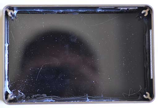
The IBOX comes in an anodized aluminum case that has a glossy plexiglas top:

top

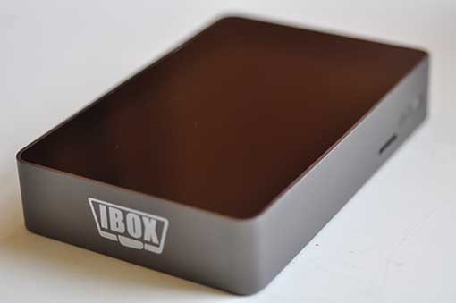
Being a pre-production sample, I’ll excuse the fact that the top had a lot of superficial scratches on it, but I wonder if a matte surface would be better, since it scratches so easily. The left side of the unit contains a plethora of connectivity:

left

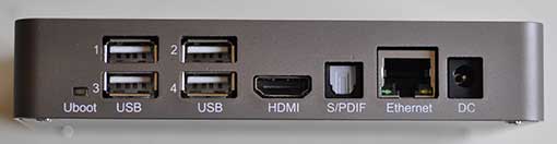
The small rectangle on the left labeled Uboot is a switch for entering the U-Boot bootloader. The right side contains a micro SD slot:

right

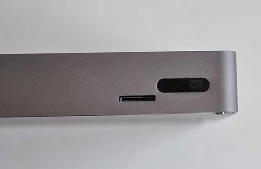
Behind the rectangular window is a 2-color status LED and an IR receiver for talking to remote controls. The back panel contains a 32-pin expansion interface connector:

back

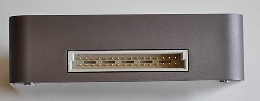
The expansion connector is what really separates the IBOX from the typical ARM mini PC. It opens up the platform for hardware hackers, containing pins for UART, TWI, SPI, SATA, etc.  You can find the full pinouts on the Indiegogo page. The bottom of the IBOX is held on with 4 Philips screws:

bottom

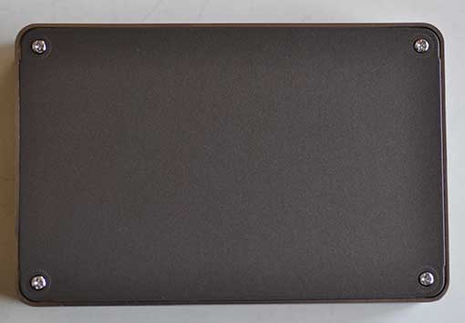
A set of rubber feet would be a nice addition.  Removing the metal bottom cover reveals the bottom of the baseboard:

botpcb

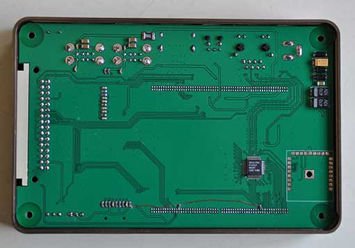
The baseboard is a very tight fit into the case.  In order to remove it, you must first pry the it away far enough to clear the various ports from their cutouts in left side of the case, and then pry upwards from the front.  The baseboard is a modular backplane which contains all of the I/O connectors, as well as the socketed core board:

pcbtop

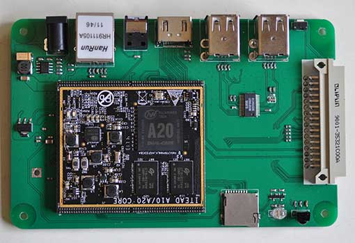
The core board is essentially the “brain” of the IBOX, containing the A20 processor, RAM, etc. Since the core board is socketed, it can be swapped out as newer, more powerful ones become available (e.g. A31, etc).  Here is a close-up of the A20 core board:

coreboard

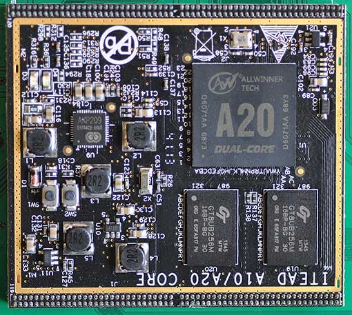
Note that there are two pushbuttons, SW1 and SW2. I’m not sure of their purpose, but they are not accessible when the IBOX is assembled. The plexiglas top was attached to my IBOX with some rather messy clear silicone caulk:

inside

Again, I’ll excuse the mess because it’s a pre-production sample. I hope that the production units will have cleaner assembly.

So far, the IBOX looks like an interesting platform for building an energy efficient media center, file server, http server, etc. I’m looking forward to powering it up and putting it through its paces. Perhaps I will use it to replace my Raspberry PI that’s currently running XBMC. In my next article, I will boot up the IBOX, and test it out.

Resources:

Indiegogo campaign – the most information can currently be found on this page.
ITEAD blog – contains various informative posts on the IBOX
A20 core board schematic
IBOX baseboard schematic
IBOX baseboard design files
Case dimensions
distro downloads

Noritake 24×6 Character VFD Module

I’ve always thought VFDs were pretty cool. They used to be the rage in high end consumer electronics. Back in the mid 70’s, I built a VFD alarm clock. Recently, I got my hands on a modern VFD module to play with. The Noritake-itron SCK-Y100-24063-N14 is a very flexible 24×6 character VFD module in the same form factor of a 20×4 character LCD module. It is a member of Noritake’s CU-Y series VFDs.

vfdardu

Overview

  • 5V supply voltage
  • serial (asynchronous and synchronous) and 8-bit parallel communication
  • CMOS signal and RS-232 (+-15V) voltage compatible
  • jumper-selectable baud rate: 9600, 19200, 38400(default), 115200.
  • extensive built-in character sets: USA, European, Japanese (Katakana only), Multilingual – various fonts and symbols, Canadian and French, Nordic, WPC1252 – european fonts and symbols, Cyrillic, Latin, Portuguese, PC858 – european fonts and symbols
  • adjustable brightness
  • locally selectable brightness for highlighting (useful for implementing menus)
  • double width, and double width & height characters

The video below compares the Noritake 26×6 VFD to a 20×4 LCD. The characters are noticeably smaller on the VFD due to the higher density, but still quite readable.

This page shows some of the versatility of the Noritake VFD: Versatile Character Display CU-Y Series

The VFD comes pre-configured to operate in async serial mode at 38400 baud. It isn’t necessary to use a UART to talk to the VFD; any GPIO pins will suffice. A minimum of 2 pins are needed, for SIN (input) and SBUSY (output). A third GPIO pin can be connected to RESET (input). I hooked mine up to an Arduino UNO as follows:

D2 -> SIN
D3 -> SBUSY
D4 -> RESET

Here’s what it looks like from the front, running Noritake’s Arduino menu demo:

vfdfront

The lower contrast on the left side of the photo is due to my camera’s reflection – the glass is very reflective. Note the highlighting via localized variations in brightness. Here’s what it looks like with a blue filter on top (again, apologies for the reflections – it actually looks a lot better than this photo):

vfdblue

Though my photos are crap, the display is quite easy to read indoors. I wouldn’t recommend it for outdoor use, however, or anywhere that you expect direct sunlight.

Back view:

vfdback

The 10-pin  jumper block on the top center is used for configuration, and the 14-pin jumper block on the bottom right is used only for parallel mode.

The writing speed of this VFD is very fast. Running in async serial mode on an Arduino UNO at 38400 baud, I was able to output 120 characters in a mere 38ms, which is about 3x faster than LiquidTWI2 can muster, even after the I2C bus is tweaked (and over 100x faster than LiquidTWI2 w/o I2C bus frequency tweaking). Unfortunately, Noritake’s Arduino library doesn’t compile on a Teensy 3.x, because it contains AVR assembly code in a timing function, and calls _delay_us(), which isn’t implemented on the Teensy 3.x. On the other hand, it should not be hard to replace these two functions. To use the Noritake VFD with Arduino, first download the Arduino code library. From the Arduino IDE’s pull-down menu, use Sketch->Import Library…->Add Library... to import Arduino_Noritake_VFD_CUY.zip. Include the following headers into your sketch:

[code language=”c”]
#include <CUY_Interface.h>
#include <CUY_Serial_Async.h>
#include <Noritake_VFD_CUY.h>
[/code]

Two classes need to be instantiated:

[code language=”c”]
CUY_Serial_Async interface(38400,2, 3, 4); // SIN,BUSY,RESET
Noritake_VFD_CUY vfd;
[/code]

Here is what initialization looks like:

[code language=”c”]
void setup() {
delay(500); // wait for device to power up
vfd.begin(24, 4); // 24×4 character module
vfd.interface(interface); // select which interface to use
vfd.isModelClass(Y100);
vfd.CUY_init(); // initialize the module
}
[/code]

Note that Noritake chose to implement only partial compatibility with the LiquidCrystal library.  So while vfd.print(s) is supported, vfd.setCursor(x,y) is not; one has to instead call vfd.CUY_setCursor(x,y). The Noritake_VFD_CUY class methods are declared in Noritake_VFD_CUY.h. Noritake includes a few sample sketches, which you can access from Arduino’s menu via File->Examples->CUY.

Noritake also provides a handy host program, which lets you configure and test the display without a microcontroller.

cue-y_373x350

To use the program, connect the VFD to a PC running Microsoft Windows via a Serial->USB adapter, such as an FTDI cable. Using the Serial->USB adapter opens up the possibility of using the VFD  as a USB auxilliary display for a PC.

The Noritake SCK-Y100-24063-N14 is a very cool device, and I’m looking forward to building a project with it.

Resource Links

SCK-Y100-24063-N14 Overview 
CU-Y: Y-Series Evaluation Software
Code Library
Arduino Library with examples
Sample C++ code and configuration/hookup
How to use custom fonts
How to use the built-in font tables
How to use the font magnification command
How to create a menu using the highlight effect