The first step in wiring up the matrix is deciding on the method. I immediately ruled out soldering, because it’s messy, slow, and smelly. Also, it incurs the risk of overheating the LED’s as well as being hard to repair. I also ruled out using crimp-on connectors due to expense. After pondering it for a while, I decided that wire wrap would be the best approach for several reasons:
- it’s cheap
- there are no toxic fumes
- there is no risk of overheating and destroying LED’s
- it’s easy to undo, so repairs are easier
- it’s relatively quick to do
- it’s as reliable as soldering – perhaps more reliable, since there’s no risk of cold-soldered joints
- the wire is so thin that it can be threaded into the gaps between the foam matrix pieces
The downside is the small wire gauge – 30AWG. I was afraid that it might too small, so I consulted some tables on the Internet, I found that it has a resistance of 105.2 Ω/1000 ft. I estimated an upper bound of 4 ft of wire, so that’s ~.4Ω – probably insignificant for this application. Next, I found that the current carrying ability (Ampacity) is estimated at .144A by most tables, but one actually had it listed at .86A. The LED’s I’m using run at a maximum of 20mA per color. In a column, a maximum of 1 LED at a time is lit, so it’s definitely in spec. On the other hand, if a whole row is driven w/ the with all 3 colors lit, we can end up with 8 x 3 x 20mA = 480mA. This is way over the .144A spec, but below the .86A spec. I decided to just try it, and if I encountered problems, I would put multiple wires in parallel for the rows.
I already had a wire wrapping tool, which ,I bought many many years ago (ouch,they seem to have gotten expensive over the past 30 years! I think I spent $5 on mine), so all I needed was some wire. Radio Shack carries 50 ft spools of red, white, and blue 30AWG kynar-insulated wire for 3.99 a roll (note: the price seems to have increased to $4.19 in the 2 weeks since I bought mine). I bought one roll of each.
I started out wiring each color in sequence along an 8-LED chain, but later found that it’s more orderly to wrap the 3 wires (R/G/B) between each pair of LED’s at a time. When I wrapped my first strand of 8 LED’s I didn’t pay attention to the orientation of the leads. This made a mess. It’s better if you orient the leads in the same direction as you wrap each chain (e.g. red pin to the left), rather than just doing it haphazardly. This way, the wires don’t criss-cross each other as much. After much experimenting, I found that a 4″ length of wire between each pair of LED’s was optimal for my 2″ ID matrix. This left enough slack between the successive LED’s to work with.
I’m using common anode 5mm diffused RGB LED’s bought on eBay from a Chinese vendor… $25 for 100. Not particularly cheap as eBay goes, but they use free trackable EMS shipping, which takes about half the time as regular HK post. The vendor sent me common cathode LED’s by mistake, so I had to wait for him to send me another batch w/ the right polarity. The pins go from left to right in the photo, B-G-Anode-R. The anode lead is longer, which makes it easier to identify. Note that since the anode is for the rows, while the other R/G/B leads are for the columns, I didn’t wire it yet at this stage. Here are the completed strands:
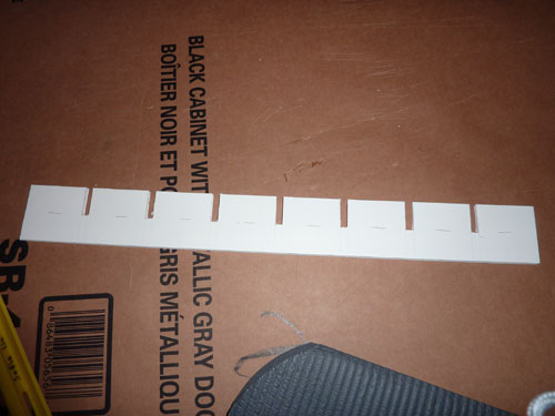
Since the LED’s will be face downwards in my matrix, my idea was to fasten them by simply poking the wires through the cardboard/foam sandwich. I found that the paper was a bit too thick to do this easily, so I had to cut slots into the matrix pieces to receive each LED. Be sure to do this before you thread the 8 LED strands into your matrix!
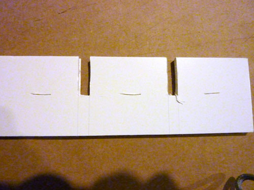
It’s hard to see the slits in the photo above. Here is a close-up:
Make sure that you cut all the way through the foam sandwich.
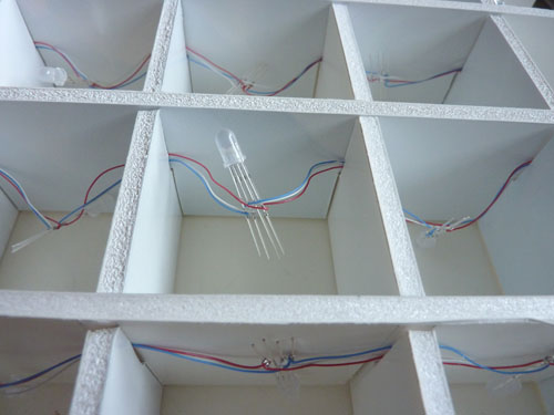
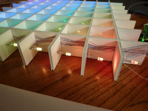
After completing the 8 chains of 8 LED’s, the next step was to thread them into my matrix. The wire wrapping wire is very thin, and easily fits into the interlocking slots of the matrix.
To wire up the rows, you need to flip over the matrix, so that you can wire and thread the row wires perpendicularly to the columns.
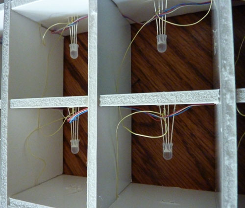
This step requires a bit more dexterity, because you have to work with the LED’s inside the matrix. Thankfully, there are only 8 rows (as opposed to our 24 (8×3) columns, so there are a lot less wires to deal with. In the photo above, notice how the I’ve flipped the matrix. The RGB wires are threaded through the bottom slots, while the yellow anode wires are threaded perpendicularly, through the top slots. Also, note how I’ve secured the LED by jamming it into the slot that I cut. The gaps among the 4 leads on each individual LED are rather narrow, so it’s a good idea to spread the leads apart before plugging them into the matrix, to avoid shorts. You might be wondering why I have the LED’s pointing sideways instead of straight up. This is because I am building a matrix which will stand up vertically, so that the light will come out both sides. Also, in my previous experiments with LED orientation, I found that the colors didn’t mix very well when the LED’s were pointed directly at the viewer.As you can see, this setup made it considerably more difficult and time consuming to build than if I had wired them pointing upwards on a single sheet of poster board.
Here is how I routed the column wires:
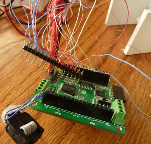
Finally, I wire-wrapped all the leads onto a pair of 16-pin male headers. The pin groups are conveniently labeled on the Colorduino, so it’s easy to figure out which wires go where.
Even so, I managed to reverse all of the green wires; since I used wire-wrap, it was easy to undo them and hook them up in the correct order. It’s a good idea to manually test all of the connections before plugging them into the Colorduino. I used a 5V supply with a 100Ω resistor and test clips to check each individual LED. Amazingly, I didn’t have any shorts. After testing was completed, I used small blobs of hot glue to secure each LED, and in each interlocking corner of the matrix.
When I finally powered it up via my USBtinyISP, I found that my PC couldn’t communicate properly with the Colorduino. The LED’s were drawing more current than the USBtinyISP could output. Hooking the Colorduino up to my 5V 1A supply fixed that.
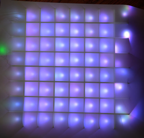
Here’s what it looks like with drafting film laid on top, and all the lights set to maximum brightness:
One very disappointing discovery is that I won’t be able to properly set the white balance on this matrix. Note the wide range of color variation among the LED’s. I guess the quality control is not so good when you buy cheap LED’s on eBay. I had the same problem even with the white LED’s that I used in my 5×5 monochrome matrix. Also, I don’t understand why the LED’s are making bright dots, since I was getting better diffusion in my initial experiments. The LED’s I used in the experiments should have been very similar.. they were from the same vendor, but were the common cathode ones that he sent me by mistake. I guess the new LED’s I received are not as diffuse as the last set he sent me.
Another discovery I made while testing is that the orientation of my wiring is wrong. I had wanted the wiring to be routed such that the Colorduino would be on the bottom. In fact, the Colorduino is positioned on the side. Therefore, I’m going to have to swap the rows and columns in software – an easy fix. I ran the matrix full brightness for a while, and the row wires aren’t melting or heating up, so the thankfully, the current carrying ability of the row wires is OK.
The wiring task was a grueling and tedious task. I spent a total of about 16 hours spread across 4 days doing it. Thank goodness for TV, or I would have gone insane. Needless to say, I’m all caught up with the recordings on my DVR! My hands ache, my back aches, my joints ache! One annoying thing about 30AWG wire is that it’s so thin that it’s hard to get a grip on it, and when it falls on the floor, it’s hard to pinch it between your fingers to pick it up. Wiring up the matrix required 256 wires (8x8x4), each wire needed to be stripped and wrapped on both ends… 512 joints to wrap!! I really felt like I was losing my mind, and that I was going to go blind. It has to have been the most tedious task I’ve ever completed!
The next step will be finishing up the matrix assembly. I still haven’t gotten the outer frame onto it.
Related articles:



I Like your project using the colorshield.
Have you added some resistors to the LED Matrix Shield or isn’t it necessary for RGB LEDs with the Colorsshield?
I checked the Layout of the PCB, there are 8 Sockets each for R/G/B but what’s with the 8 Anode PINs? Are they connected to C0-C7 or to the VCC next to Green?
Have you used:
SDA, SCK, SB, LAT, RSTn?
Help would be highly appreciated 😀
Thanks
Andi
Thanks for idea of wire wrapping instead of soldering the little buggers.