REVISED 20180116
In my previous article, HowTo: Upgrade Scosche Rhythm+ Firmware, I showed how to update Scosche Rhythm+ firmware via their Fitness Utility iOS app. Some people have had issues with the 3.01 firmware installed by the latest V2 Fitness Utility, notably incompatibility with certain apps, and/or flaky readings.
I contacted Scosche via live chat, and they told me that there was no way to downgrade from 3.01, except for sending the unit back to them. The V2 Fitness Utility no longer has a Firmware Update button, so there’s no way to use it to install any firmware other than v3.01. Instead of sending mine back to them, I decided to try to get a hold of an older version of Fitness Utility, in order to downgrade the firmware. It turned out to be a very laborious and time consuming procedure. I was hoping that I could share the IPA file of Fitness Utility 1.4.1 so everyone else could save a lot of time, but as reader Hap noted in the comments below, IPA files are tied to specific Apple IDs.
If you want to downgrade your firmware yourself, rather than send it back to Scosche, follow the rather lengthy and complicated procedure below.
To obtain the older version of Fitness Utility, I loosely followed the procedure from How to legally download any previous version of an App Store app through iTunes, but it was somewhat outdated, so I will summarize my own procedure below. I am not going to explain the nuts and bolts of what each step does, since that’s covered in the linked article.
Current versions of iTunes no longer support app installs, so you need to downgrade to an older version. The linked article states that there’s yet another hurdle, in that as of iTunes 12.5, Apple is using certificate pinning, which nullifies the ability of Fiddler to snoop HTTPS traffic. I tried an older version of iTunes, but it was no longer able to communicate with the App Store (Apple just LOVES to put up hurdle after hurdle for us!). After much searching, I discovered that in December 2017, Apple quietly released iTunes 12.6.3 for enterprise users who still need the ability to do app installs. Because it uses certificate pinning, I had to devise a procedure to get around that.
Note for Mac users: You can probably follow the same basic procedure using Charles Proxy, but I don’t have the ability to walk you through that.
WARNING: THE PROCEDURE BELOW IS PROVIDED AS A RESULT OF MY OWN FINDINGS. THERE IS ABSOLUTELY NO WARRANTY, AND THERE IS A SMALL POSSIBILITY THAT YOUR DEVICE CAN BECOME BRICKED DURING A FIRMWARE UPDATE. MAKE SURE THAT YOUR DEVICE IS FULLY CHARGED BEFORE STARTING. IN FOLLOWING THE INSTRUCTIONS BELOW, YOU AGREE TO RELEASE ME FROM ALL LIABILITY, AND PROCEED AT YOUR OWN RISK.
How to download Fitness Utility 1.4.1 and use it to downgrade your Rhythm+ to firmware 2.62:
-
- Find your current iTunes folder, and rename it to iTunes.sav, or just move it to a new location. On Windows 10, it’s located at C:\Users\<yourusername>\Music\iTunes. (Don’t worry, after you’re done, you can reinstall the latest iTunes, and restore your old iTunes folder).
- Download and install iTunes 12.6.3
- Download and install Fiddler. DO NOT START FIDDLER YET
- Launch iTunes 12.6.3 and download any random app. iTunes will prompt you to log in with your Apple ID. This is the loophole we use to get around the certificate pinning. It turns out that iTunes 12.6.3 only checks the certificate during the login process, and doesn’t detect when we later swap in Fiddler‘s fake root certificate so that it can snoop HTTPS traffic.
- Before proceeding, it’s best to kill any programs on your computer that access the web, because they will pollute your Fiddler capture. If you have your web browser open in order to read this article, kill all of your other tabs that might be accessing the web in the background.
- Launch Fiddler.
- In Fiddler, go to the File menu and uncheck File->Capture Traffic
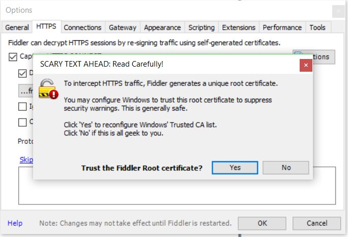
- From the Fiddler menu, go to Tools->Options->HTTPS. Check the Capture HTTPS CONNECTs and Decrypt HTTPS traffic checkboxes. A dialog box will pop up asking if you want to Trust the Fiddler Root certificate. Select Yes to it, and all of the ensuing dialog boxes. Don’t worry, after we’re done, we will remove the fake certificate, and restore your original.
- In Fiddler, go to the menu to check Rules->Automatic Breakpoints ->Before Requests
- Launch iTunes and search for Fitness Utility in the App Store
- In Fiddler, go to the File menu and check File->Capture Traffic
- In iTunes, click the button to download Fitness Utility
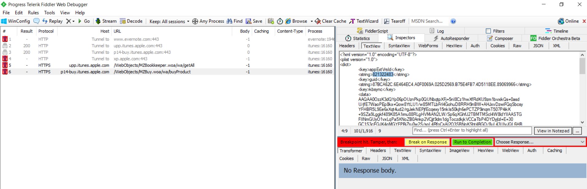
- A few requests with red icons on the left will appear in the Fiddler capture pane. Select
HTTP Tunnel to upp.itunes.apple.com:443 and click the green Run to Completion button in the right pane. Next, select
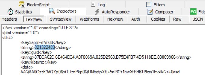
HTTP Tunnel to p14-buy.itunes.apple.com:443 in the left pane, and click the green Run to Completion button in the right pane - A new request should appear in the Fiddler capture pane: HTTPS p14-buy.itunes.apple.com /WebObjects/MZBuy.woa/wa/buyProduct Select it in the capture pane, and then in the right pane, click the TextView tab, look for
<plist version=”1.0″>
<dict>
<key>appExtVrsId</key>
<string>821322483</string>and replace 821322483 with 813634417.
- In Fiddler, go to the menu to check Rules->Automatic Breakpoints ->Disable
- Make sure the HTTPS p14-buy.itunes.apple.com /WebObjects/MZBuy.woa/wa/buyProduct request is selected in the Fiddler capture pane, and click the green Run to Completion button.
- After iTunes shows that Fitness Utility is downloaded, verify that you have the Fitness Utility 1.4.1.ipa file in C:\Users\<yourusername>\Music\iTunes\iTunes Media\Mobile Applications
- Connect your iOS device to your computer, and use iTunes 12.6.3 to install the Fitness Utility 1.4.1 to your iOS device, or use iFunBox instead as described below in Update 20170112
- Launch Fitness Utility 1.4.1 on your iOS device and turn on your Rhythm+. WARNING: MAKE SURE YOUR RHYTHM+ IS FULLY CHARGED BEFORE UPGRADING THE FIRMWARE. IF IT DIES DURING A FIRMWARE UPGRADE, IT MAY BE RENDERED UNUSABLE.
- Tap the Commands button at the top right of the screen, and then tap the Start button next to Firmware Update.
- After the update is completed, power cycle your Rhythm+
- You can check that the firmware version is now 2.62 by tapping the Attributes button at the top left of Fitness Utility.
- VERY IMPORTANT: Once you verify proper operation of Fitness Utility, on your computer, have Fiddler restore your original root certificate with Tools->Options->HTTPS->Actions->Reset All Certificates.
- Copy your Fitness Utility 1.4.1.ipa file somewhere so that you can reuse it in the future if you wish.
- Delete the new iTunes folder, restore your old iTunes folder by renaming iTunes.sav to iTunes, uninstall iTunes 12.6.3, and reinstall your original version of iTunes.
Now that you have your own copy of Fitness Utility 1.4.1.ipa, you are free to try any future firmware upgrades from Scosche, because it’s easy to go back to a working version if you don’t like the new one. If you use iFunBox, you don’t even have to mess with swapping out iTunes versions.
If you prefer to downgrade to firmware v2.4, you can use Fitness Utility 1.4.1 and follow the procedure below:
*** WARNING: DOWNGRADING TO FIRMWARE V2.4 DISABLES THE ABILITY TO UPDATE FIRMWARE VIA FITNESS UTILITY. IF YOU LATER CHANGE YOUR MIND, AND WANT TO INSTALL A DIFFERENT VERSION, YOU WILL HAVE TO SEND THE UNIT BACK TO SCOSCHE. ***
- download firmware 2.4 and unzip it.
- send the unzipped HEX file to an e-mail address accessible from your iOS device
- open the e-mail you sent on your iOS device, tap the attachment, and then scroll through the on screen icons until you find Copy to Fitness Utility, and tap the icon.
- Turn on your Rhythm+ and follow steps 19-22 above.
The above method actually works with any version of firmware HEX file that you are able to obtain.
Update 20180112: I tried installing Fitness Utility 1.4.1.ipa with iFunBox instead of iTunes, and it also works. Launch iFunBox with your phone connected to your computer, and install the app by clicking the Install App(*.ipa) from the main screen. Firmware 2.4: scosche-rhythmplus-2_4.zip
Downloads:
iTunes 12.6.3 (allows App installs): https://support.apple.com/en-us/HT208079
Previous article: HowTo: Upgrade Scosche Rhythm+ Firmware


