Converting Cheap Chinese USBHID Fake USBasps Into Real USBasps

I recently ordered some USBasps from Amazon, which looked interesting, because unlike the typical USBasps, which are just bare PCBs, these had metal cases:

They are also common on AliExpress.

Unfortunately, when I plugged one into my computer, it detected as a USBHID device with VID=03EB and PID=C8B4, rather than as a USBasp. I tried overriding the USBHID driver on my Windows 10 machine, but that didn’t work.

Thankfully, after doing a bit of searching on the Internet, I found that others had encountered the same problem, and had found a solution. It seems that the firmware loaded into these things from the factory is proprietary, and require that you use the manufacturer’s janky software … it’s not AVRdude compatible!

Thankfully, the hardware is actually compatible w/ USBasp firmware with a minor tweak, and you just have to flash it with modified USBasp firmware.

I have a bunch of real USBasps, so I used a USBasp to convert the fakes into real USBasps! In order to program it, slide off the metal case. Next need to connect a jumper across the two holes labeled –> UP <–. The jumper enables programming of the onboard ATmega88V. Then plug it into your other USBasp or other ISP programmer, using the 10-pin ICSP cable:

So where do you get the special firmware? GreenPhotons has graciously compiled a modified firmware for us. Next use AVRdude to program the USBasp firmware into our target:

avrdude -cusbasp -pm88 -Uflash:w:20161227_mega88_usbasp.hex

You can use any ISP you already have, if you don’t have another USBasp. Just substitute the programmer in the -c parameter (e.g. -cusbtiny for a USBtiny). If you don’t have another ISP programmer, you can use an Arduino. This guy shows you how, as well as another way to get firmware.

If you get the following error, then your USBHID ISP has an ATmega88P instead of an ATmega88V

D:\hacking\arduino\USBasp\convert_usbhid>avrdude -cusbasp -pm88  -Uflash:w:20161227_mega88_usbasp.hex

avrdude: AVR device initialized and ready to accept instructions

Reading | ################################################## | 100% 0.02s

avrdude: Device signature = 0x1e930f
avrdude: Expected signature for ATMEGA88 is 1E 93 0A
         Double check chip, or use -F to override this check.

Just substitute -pm88p for -pm88 in the avrdude command line:

avrdude -cusbasp -pm88p -Uflash:w:20161227_mega88_usbasp.hex

If you have an old copy of avdude that doesn’t like -pm88p, you can instead use -F to force avrdude to ignore the device signature:

avrdude -cusbasp -F -pm88 -Uflash:w:20161227_mega88_usbasp.hex

Downloads:

modified ATmega88 firmware for USBHID USBasp

References:

Making USBasp Chinese Clones Usable

Hacking An AVR Programmer

Hacking An AVR Programmer II

I found this great resource after writing this article:

USBasp on a Clone

How to Dramatically Speed Up AVRDUDE with USBasp or USBtinyISP Programmers

AVRDUDE has a little-known command line parameter, -B, which sets the bitclock, and can dramatically speed up writing/reading firmware to/from an AVR MCU when using a USBasp or USBtinyISP. For a USBasp, simply add -B0.5 to your command line parameters. Example:

avrdude -cusbasp -B0.5 -pm3280 -U flash:w:firmware.hex

In my tests, adding -B0.5 reduces the time to write & verify a hex file by about 2/3! For the USBtinyISP, add -B1 to your command line parameters. Example:

avrdude -cusbtiny -B1 -pm3280 -U flash:w:firmware.hex

The speedup is even more dramatic with the USBtinyISP. In a specific test, I found that write/verify time dropped from 59 sec to 17 sec!

You can also speed up programming from the Arduino GUI. Simply edit your programmers.txt file. In older versions of Arduino, it can be found in <ArduinoFolder>/hardware/arduino/avr/boards.txt. For Arduino 1.8.x, it’s located in C:\Users\<YourUserName>\AppData\Local\Arduino15\packages\arduino\hardware\avr\<version>\programmers.txt.

For the USBasp, add the -B0.5 parameter to the usbasp.program.extra_params line:

usbasp.program.extra_params=-Pusb -B0.5

In order to realize the speed gain in programming, the USBasp must have firmware which supports the setting of SCK. If AVRDUDE gives you this warning:

avrdude: warning: cannot set sck period. please check for usbasp firmware update.

then you must update your USBasp’s firmware. Follow the instructions in my article:
How to Update the Firmware on a USBasp V2.0

For the USBtinyISP, add the -B1 parameter to the usbtinyisp.program.extra_params line:

usbtinyisp.program.extra_params=-B1

If the Arduino GUI is already running, you must restart it in order to load the new settings.

EKitsZone UNO Rev.3 First Look

I recently decided to buy an Arduino UNO R3, to test compatibility with my sketches, which I have been testing w/ a Deumilanove.  The UNO R3 contains an ATmega16U2  instead of an FTDI chip to do the serial to USB conversion, as well as 3 extra pins on the digital side of the board: SCL/SDA/AREF.  One thing I don’t like about the Arduino UNO is that while it uses a 16MHz crystal for the 16U2, the main 328P MCU runs on a resonator, which is not as accurate.  I found the EKitsZone UNO Rev.3 on eBay for $14.99, and decided to give it a try.

unor3The notable differences in the EKitsZone Rev.3 versus the Arduino UNO R3 are:

  1. the ATmega328P uses a 16MHz crystal oscillator instead of a resonator, so its timing is just as accurate as a Deumilanove
  2. the reset button is mounted at a right angle, so it’s easily accessible even when a shield is attached on top
  3. it uses a mini-USB connector instead of a full-sized one
  4. the JP2 pins aren’t filled with solder, so it’s easier to solder in headers, should you want to connect something the PB4..PB7 pins on the 16U2
  5. the programming header for the 16U2 isn’t installed, but it’s easy to solder one in

I see 1-4 as advantages.  Plus, the board is a cool looking red color.

AT90CAN Support for Arduino 1.0+

I have adapted the Arduino AT90CANxx support to work with Arduino 1.0+. Also, I have moved the code to github, so that it will be easier to update.  Note that the Arduino 1.0+ support is currently only alpha quality.  I have compiled a few sketches, but I also have found some which currently can’t compile.

You can always download the latest version at https://github.com/lincomatic/AT90CAN

It is easiest to download the whole repository as a zip file: https://github.com/lincomatic/AT90CAN/zipball/master

Follow the instructions in the README file.  For more information, see the post linked below.

Related Post: AVR CAN Bus Project – Step 1: Programming AT90CAN128 with Arduino

Bootloaders for AT90USB1286

While the AT90USB1286 MCU in the Teensylu/Printrboard can be programmed with an ICSP or JTAG programmer, you can also install a bootloader, which will allow you to program it via a USB connection alone. Besides the convenience of not having to attach a hardware programmer, uploading firmware via a USB bootloader is blazingly fast. Also, it allows you to write host software to do end user firmware upgrades without a hardware programmer.

I am currently aware of 3 bootloader options for the AT90USB128x MCU’s:

DFU – USB Device Firmware Upgrade Class

This is the bootloader officially supported by Atmel.

PRO: Works with Atmel FLIP tool.

CON: requires libusb device driver; no command line tool available for Windows.  For Linux, an open source host loader app is available; can’t integrate into Arduino IDE

CDC – USB Communication Device Class

PRO: can integrate into Arduino IDE; works with avrude via avr109 protocol.

CON: requires user to know which virtual serial port it’s associated with; in Windows, uses native Windows driver, but requires INF file install, needs upgrade of avrdude to newer version for Arduino < 1.0.

HID – USB Human Interface Device Class

PRO:  Trouble free – doesn’t require any device drivers – just plug and play

CON: doesn’t integrate into Arduino IDE


Fuse Settings

Before you can install a bootloader on your MCU, you must set the fuses correctly to allocate space for it.  We need 4K bytes (2K words) of space, so using the Engbedded Atmel Fuse Calculator, we see that we need Boot Flash Size BOOTSZ=01,  which is in the high fuse.  Here are the fuse settings that I use on mine:

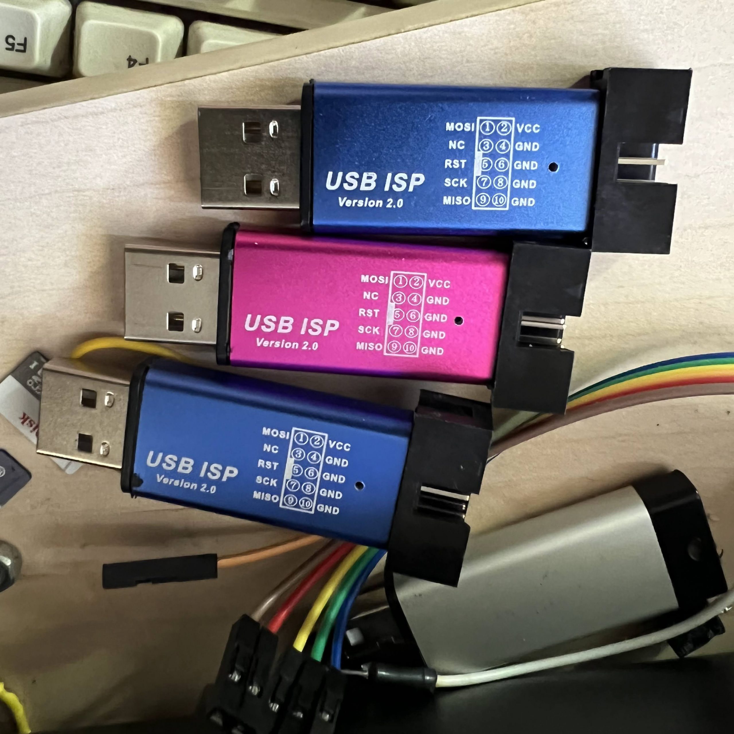
avrdude -c usbtiny -p at90usb1286 -U lfuse:w:0xde:m -U hfuse:w:0xdb:m -U efuse:w:0xf0:m

BE CAREFUL IF YOU WANT TO FIDDLE WITH FUSE SETTINGS YOURSELF.  It’s not hard to “brick” your AVR with the wrong settings.  In fact, when I was first working with my Printrboard, I managed to brick it by messing up the CKSEL bits, thinking I was supposed to set it for an external oscillator.  Luckily, all I had to do was connect an external oscillator (I used the signal generator function of my DSO Quad mini scope) to XTAL1 and then use avrdude to fix the offending fuse.  If you do something worse, like disabling SPIEN by accident, you might have to resort to HV programming.  Here is some info on recovering a bricked AVR:  http://www.larsen-b.com/Article/260.html

Note that I have set hfuse = 0xdb, which disables the JTAG interface.  This makes more I/O pins available (in particular, some of the pins exposed on the I/O headers of Printrboard).  If you want to use a JTAG programmer, you should instead set hfuse = 0x9b.

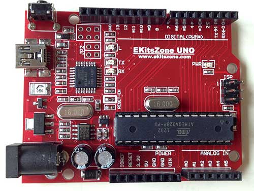
Once your fuses are set correctly, use avrdude with your programmer to upload the bootloader.  After your bootloader is installed, you don’t need to use the programmer anymore – just a USB connection is enough.

Booting into Bootloader

Once a bootloader is installed (see instructions below), the bootloader must be activated when you want to upload firmware.  To boot the AVR into the bootloader instead of normal program code, you must tie the HWB pin to ground during a RESET pulse.  To to this on Teensylu or Printrboard, simply remove the 2-pin jumper that’s next to the AT90USB1286 chip, then press and release the reset button.  You can then replace the HWB jumper.

NOTE: If you have a Printrboard RevD, the jumper has been reversed, and needs to be INSTALLED to get into the bootloader, and REMOVED to run your firmware.

Below, I describe how to install and use each of the bootloaders.  For Arduino IDE integration, use BootloaderCDC.  I also like BootloaderHID, because it doesn’t need drivers, and doesn’t require selecting a virtual serial port.

DFU Bootloader

  1. Download and install FLIP. FLIP will also install the device driver.
  2. Download BootloaderDFU.zip. I built this one for AT90USB1286 from LUFA-120219.
  3. Install with avrdude: avrdude -c usbtiny -p at90usb1286 -U flash:w:BootloaderDFU.hex:i (note if using a usbtiny and avrdude complains of a verification error at byte 0x1f000, ignore it)
  4. To flash hex files to board, after Booting into Bootloader, use FLIP or dfu-programmer.

CDC Bootloader

  1. Download BootloaderCDC.zip.  I built this one for AT90USB1286 from LUFA-120219.
  2. Install with avrdude: avrdude -c usbtiny -p at90usb1286 -U flash:w:BootloaderCDC.hex:i (note if using a usbtiny and avrdude complains of a verification error at byte 0x1f000, ignore it)
  3. To flash hex files, you’ll need a newer version of avrdude than the one included with Arduino < v1.0.  The version I use is 5.10.  After Booting into Bootloader (the first time, Windows might want a driver … point it to the INF file that I included) , type:  avrdude -c avr109 -P port -p at90usb1286 -U flash:w:firmware.hex:i, substituting your Printrboard’s CDC serial port for port, and the name of your hex file for firmware.hex.
  4. If you want to flash directly from the Arduino IDE, follow my instructions for installing my at90usb1286txt.zip files into Arduino.  Then, after restarting Arduino and Booting into Bootloader, select [BootloaderCDC]Teensylu/Printrboard from the Arduino Tools->Board menu.  Then select the serial port associated with your board.  Hit the Upload button in the Arduino IDE to compile and upload your sketch.

HID Bootloader

  1. Download BootloaderHID.zip. I built this one for AT90USB1286 from LUFA-120219.
  2. Install with avrdude: avrdude -c usbtiny -p at90usb1286 -U flash:w:BootloaderHID.hex:i (note if using a usbtiny and avrdude complains of a verification error at byte 0x1f000, ignore it)
  3. To flash hex files, after Booting into Bootloader, type:  hid_bootloader_cli -mmcu=at90usb1286 -w -v firmware.hex, substituting the name of your hex file for firmware.hex.  I’ve included the Windows binary.  For Linux or OSX, you can build hid_bootloader_cli yourself from the LUFA sources.

NOTE: When uploading a bootloader to the AT90USB1286 using a USBtinyISP, you will get a verify error from avrdude.  You can safely ignore it.  The problem is that the USBtinyISP has a bug with reading flash memory above the 64K (10000h) boundary.  However, it can write it without problems.

How to Program an AT90USB1286/Teensylu/Printrboard with Arduino and USBtinyISP

My first step in loading Marlin RepRap firmware into the Printrboard is to get Arduino to play nicely with it.  The method I am going to describe in this article for programming a Printrboard with Arduino will work with the Teensylu or any other device that uses the AT90USB1286 and has an ICSP connector.   The programmer we are going to use is a USBtinyISP or compatible. Since the AT90USB1286 isn’t officially supported by Arduino, it takes a bit of setting up to get things working properly.

I first looked at the instructions on Teensylu’s page in the RepRap wiki, but found them very confusing, and I didn’t like the idea of having to send the HEX file to the MCU using an external utility instead of doing everything within the Arduino IDE. So, I set out to streamline the process and document it as I went.  If you follow my method below, you’ll be able to compile and download your firmware all within the Arduino IDE.

Step 1: Download and install Teensyduino

Teensyduino was created by PJRC for their Teensy line of boards.  Teensy is a great alternative to Arduino if you want an ultra compact board with built in USB.  The Teensy++ happens to also use the AT90USB1286, so it’s compatible w/ Printrboard/Teensylu.  Follow PJRC’s instructions for installation from the download link.

If you only plan to program for RepRap, you don’t need to install any of the libraries.  On Windows, you will be prompted to install the serial driver. Select yes.  You don’t have to worry when Windows complains that the driver is unsigned… it’s just an INF file to tell Windows to use one of its own built-in drivers.

Step 2: Modify Teensyduino Configuration for use with USBtinyISP

Download at90usb1286txt.zip.

Navigate to where your Arduino files are located.  On my computer, I have them in d:\arduino-0022.  We will call this <arduinofolder>.  Now, find the subfolder where the Teensyduino library was installed:

<arduinofolder>\hardware\teensy

If you are in the correct folder, you should already see a boards.txt and a subfolder called core in there.  Drop the files from at90usb1286txt.zip into that folder, overwriting the existing boards.txt.  You should see something like this:

If you don’t plan to develop with any of PJRC’s Teensy or Teensy++ boards, you can keep them from showing up in your Arduino menu by copying boards.txt.nopjrc over boards.txt.

Now, when you start Arduino, you should see some new configurations in the Tools->Board menu.  The important ones are:

[usbtinyisp]AT90USB1286
[usbtinyisp]Teensylu/Printrboard
[BootloaderCDC]AT90USB1286
[BootloaderCDC]Teensylu/Printrboard

To use a USBtinyISP programmer, select either [usbtinyisp]AT90USB1286 or [usbtinyisp]Teensylu/Printrboard. The only difference between the two configurations is that I took the extra useless options out to make things simpler when programming Teensylu/Printrboard.  The Teensylu/Printrboard option is the same as the AT90USB1286 option with USB Type = Serial and CPU Speed = 16MHz.

At this point, you can plug in your USBtinyISP and into your AT90USB1286/Teensylu/Printrboard and start programming!

So what are the [BootloaderCDC] configurations for?  They allow you to download sketches into your target board directly through a USB connection to your host, without the USBtinyISP programmer.  See my next article for details on how to do that.

Update 20140909: I have uploaded a copy of Arduino 1.0.5-r2 for Windows to github, which is already modified to work with the AT90usb1286, so you don’t have to modify it as above. Simply go to https://github.com/lincomatic/arduino-1.0.5-r2-at90usb1286 and click the Download Zip button, and then extract the contents to your PC. My distribution also supports the USBasp in addition to the USBtinyISP.

RepRap – 3D Printing Project Kickoff – Printrboard First Look

I have been somewhat intrigued by the RepRap project, an open source 3D printer movement, for several years.  However, wasn’t motivated enough to jump into the fray until late last year, when I saw Brook Drumm’s Printrbot on Kickstarter.

With only about 1 hour left before funding closed, I pledged $500 to get a Printrbot kit. While I could have started from scratch, and built a Prusa Mendel, after reading about how much tweaking is involved in building and setting up a RepRap, I decided to start with a Printrbot – a cute, compact, and simple design, and the most inexpensive RepRap at the time.  Printrbot’s Kickstarter was a smashing success.  They raised an astonishing $830K. Unfortunately, the gigantic amount of orders they received means that mine will take a little longer to get to me than I originally anticipated. So, I’ve been immersing myself in the intricacies of the electronics, firmware, host software, and mechanical aspects of RepRap for the past couple of months.

There are a variety of popular controller electronics for RepRap, the most popular being RAMPS.  The electronics are one of the largest costs of building a RepRap.  Although RAMPS is convenient, because it’s based on an Arduino Mega, I like the idea of having a single dedicated board.  The Printrbot folks have designed their own controller board, which they call Printrboard.  Although Printrbot is not yet selling Printrboards, the design is open source, and thus, I was able to obtain one before their release.

Kang, a fellow RepRapper from Seoul, Korea, built a few Printrboards and sent me one to play with.

Printrboard is a fork of Teensylu, an AT90USB1286/AT90USB1287 based RepRap controller.  I like the fact that these boards are based on the AT90USB128x MCU’s because they have built-in full USB support, eliminating the need for an external serial->USB bridge IC; additionally, the native USB support means that communication with the host computer is blazingly fast – 12Mbps rather than 115200kbps.

There are a few notable differences between Printrboard and Teensylu.  Printrboard is a single board solution.  First, Printrboard adds an integrated SD card reader.  This is handy for printing while untethered to a computer.  Teensylu has I/O pins which can be used to easily add an SD card reader.

Second, the stepper motor drivers are integrated onto Printrboard’s PCB, while Teensylu uses plug-in Pololu/Stepstick carriers.  The advantages of integrating the stepper drivers onto the main PCB are reduced cost and compactness.  The downside is that it is not uncommon to blow up a stepper driver IC, so having them soldered in means if one goes bad, the whole board is unusable.

Third, Printrboard uses Allegro A4982’s in a 24-TSSOP package, while Pololu/Stepstick use the Allegro A4988 in a 28QFN package.  The TSSOP package is considerably larger, and has a wider pin pitch, which makes reworking the board easier if one of them blows out; the 28QFN is very tiny and not for the faint of heart.  The other difference between the A4982 and A4988 is that the A4982 only supports full/half/quarter/sixteenth stepping, while the A4988 also supports one eighth stepping.

Some other minor differences between Printrboard and Teensylu are that while Printrboard only supports a 12V2 ATX power input, Teensylu gives more power options.  Also, Teensylu has a large USB-A socket, while Printrboard uses a micro USB-B socket.

I am diving into figuring out how to load Marlin RepRap firmware into Printrboard/Teensylu, to keep my end of the bargain with Kang.  A series of articles will follow with my findings.

AVR CAN Bus Project: Step 4 – LeafCAN: Nissan Leaf SOC Meter

I have implemented a SOC (State of Charge) meter for the Nissan Leaf. Many thanks to garygid and others from the MyNissanLeaf forums, for their help in decoding the Leaf CAN bus messages, and figuring out the pinouts.

The top line shows the SOC%, raw SOC value, and number of charge bars displayed in the dash.
The second line shows battery pack voltage and current in amps.

You can download the Eagle CAD schematic and AVR (Arduino) code from github:  lincomatic / LeafCAN
The Eagle schematic uses the Sparkfun library.

The schematic shows how to implement the entire circuit, without using the Olimex AT90CAN128 breakout board.

My original intent was to make a small PCB that directly attached to the LCD, and put it into a small case, but I never got it past the breadboard stage.  Unfortunately, I have gotten busy with other projects, so I am probably not going to do further development on this device nor finish the PCB layout, unless there is a large amount of interest. However, feel free to adapt it as you wish for your own CAN bus projects. Do bear in mind, however, that the design is licensed via the GPL, so if you use it for a commercial project, you must openly share your design.

Previous: AVR CAN Bus Project – Step 3: CANspy CAN Bus Monitor
Next: LeafCAN v1.1 Released

AVR CAN Bus Project – Step 3: CANspy CAN Bus Monitor

Sorry for the delay in posting the circuit and schematics from my AVR CAN Bus Project – Status Update 1.  The circuit for interfacing the Olimex AT90CAN128 Header Board is incredibly simple, and only requires 3 components.

Parts List
(1) .1uF ceramic capacitor
(1) 10K resistor
(1) Microchip MCP2551 CAN transceiver

Schematic

If you’re going to connect it to a Nissan Leaf, the car has 3 different CAN buses accessible via the OBD-II connector. The pinouts can be found on MyNissanLeaf.com in this thread: Leaf CANbus Decoding (Open Discussion)

To communicate with the AT90CAN128 header board from my PC, I connected a USB to serial converter to USART0: TXD0 (pin 3) and RXD0 (pin 2).

Arduino Sketch

Below is my CANSpy sketch for monitoring the CAN bus via the serial port, as depicted in my Status Update 1.

Download: CANspy.zip

To compile the sketch, follow the instructions in AVR CAN Bus Project – Step 1: Programming AT90CAN128 with Arduino.

In my next update, I’ll show how to implement a SOC (State of Charge) meter for the Leaf using a LCD display.
Previous: AVR CAN Bus Project – Status Update 1
Next: AVR CAN Bus Project: Step 4 – Nissan Leaf SOC Meter