NOTE: This is just a repost of an article that originally appeared in my geekmatica blog back in 2007. I’ve re-posted here, because it’s referred to by my Build Ganzfeld-style Photic Goggles (AVS Lightframes) article.
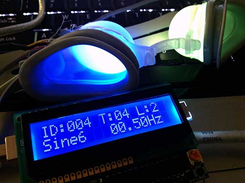
Commercial mine machines are quite expensive, and often inflexible, containing only a few canned programs. In this series, I will show how to build an infinitely reconfigurable photic-stim mind machine on the cheap. Rather than build an oscillator circuit, we will drive our mind machine with computer-generated waveforms via an audio player. You can use your favorite audio playing program on your computer, or a portable MP3 player.
UNDER CONSTRUCTION: I still have a ways to go w/ filling in details, but I thought I would at least throw up the article first, since it might take me forever. Please pardon the omissions.
Keywords: DIY, build, mind machine, brain, AVS, photic goggles, audio visual stimulation, lightframesPart 1A: Photic-stim Goggles (aka Lightframes)
Photic-stim goggles cost typically more than $50, but they’re typically built with only <$1 worth of LED’s, and some cheapo ski-type sunglasses.
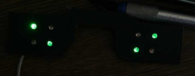
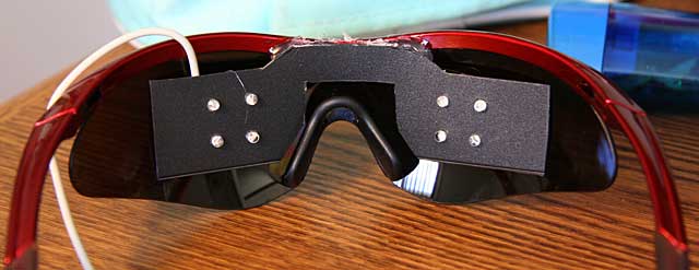
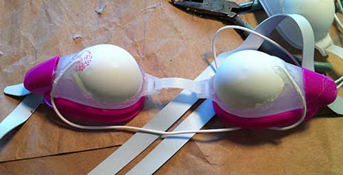
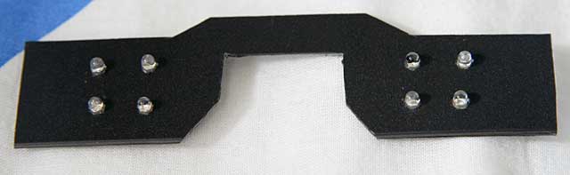
Below are the lightframes which came with my Sirius AVS machine, which I purchased from MindModulations.com.
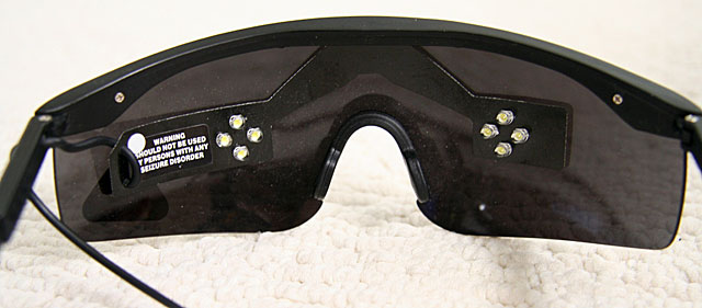
Note how they are just as I described above, a cheap pair of ski-type sunglasses, with 8 LED’s wired into a sheet of black plastic. The plastic is attached to the sunglasses with double stick foam tape.
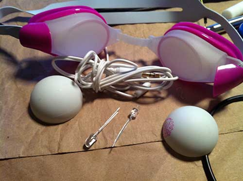
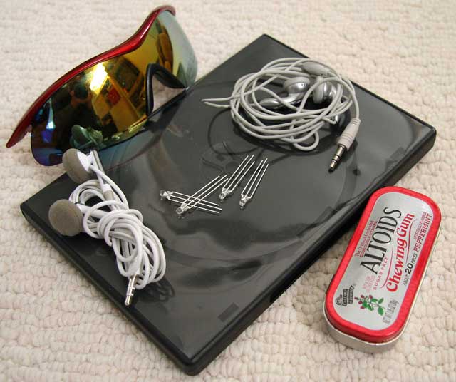
Below are the materials we need for our project:
Bill of Materials (BOM)
- Ski goggle style sunglasses. I purchased this pair for under $10
- Stereo wiring with 1/8 in phone plug. A cheap pair of earbuds from a local 99 Cents Only Store is perfect for cannibalizing.
- Thin, flexible black plastic sheeting. A spare DVD case courtesy of junk mail from AOL will do fine.
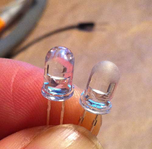
- LED’s. The type and number of LED’s is up to your own taste. Since my design uses the black plastic sheet insert, I picked 3mm LED’s… they need to be small enough that they won’t bump into your eyes when you’re wearing the goggles. If you want to drill directly into the goggle lenses and eschew the plastic sheet, you can use bigger LED’s. I bought my LED’s from UniqueLEDS.com. They have an extensive selection, and list detailed specs for the LED’s, including brightness. SUPERBRIGHT
- Not pictured is a few inches worth of hookup wire. I had some kynar-insulated 40AWG wire wrap wire laying around, which was perfect, due to its extremly thin diameter.
How many LED’s you use is up to you, but the minimum is two, one for each eye. I decided to use 8 … 4 for each eye. Also, I used two different colors, green and blue, on alternating diagonals. Note that my LED’s have 3 leads instead of the usual two. This is because I had a wild idea of using bicolor LED’s so that I could get different color combinations, but I’m not very sensitive to the colors, so I decided to hook them up like one-color LED’s. There are various recommendations on the web for color selection. Personally, I like the bright white LED’s that my Sirius frames used, but I decided to experiment with colors on this set.
First, cut the black plastic which will support your LED’s. Ask I said above, you can skip this step, and drill directly into the lenses, but it will look a lot uglier, since the wiring will be exposed in the front. Also, the drilling method doesn’t let you easily reconfigure the frames if you change your mind about the layout. I used graph paper to make a paper template for my LED layout:
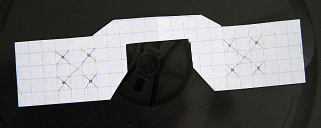
You should lay out the LED’s so that they’re fairly well-centered over your eyes. If you space them out a bit, it will allow for inaccuracy, and eye movement. Note that my layout is rotated 45 degrees with respect to the layout used by the Sirius. My DVD case was soft enough that I could just use scissors to cut out the template, but you may need to use an X-acto knife.You can use a drill for the holes, but I spun an X-acto knife around, instead, and slowly increased the size of the holes until I had a tight fit. (BTW, for the curious, those are not my hands in the photo).

I misaligned one of the holes a bit, as will be apparent in later photos, but it works fine, even though it’s a bit ugly.
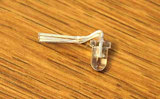
Since we want to keep the LED’s far enough away that they don’t hit your eyes, we need to bend the leads as tightly as possible. I used a pair of needle-nosed pliers, but if you’re careful, you can just use your fingers on the edge of your desk:
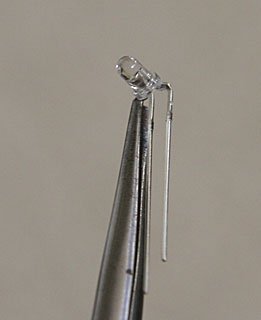
Here’s what they look like when they’re done. Since my layout uses alternating colors on the diagonals, I first bent two of the green LED’s. Then, I bent another pair of green LED’s in the opposite direction. The opposite polarity of the bending is important, because the LED’s are hooked up in parallel. Here’s what they look like before I cut the leads:

Now, the wiring and layout of the leads will vary considerably, depending on how you want your LED’s to behave. The lightframes I built behave very differently from the Sirius lightframes, which utilize the industry standard wiring. In the Sirius setup, all 4 LED’s on a particular side light up synchronously. The left side responds to the left channel, and the right side responds to the right channel, so the two sides can be controlled independently. This is an example of how they can blink:

My design mimics the IC/D setting of TC-Softworks lightframes, hooks up each pair of diagonals together. The greens respond to the right channel, and the blues respond to the left channel. Therefore, both eyes are always lit, but the intensity and color can vary.
You can use your imagination to come up with your own unique design.
If you are building your goggles to work with a particular mind machine, be aware that there is another variation in the wiring, which affects the compatibility. All of the schematics I have shown up to now have used Common Ground (CG) wiring, where the cathodes (grounds) are all tied together. Some machines, such as my Sirius, use Common Power (CP) wiring, where the anodes (power) are tied together. Before wiring up your goggles, make sure you know if you need CG or CP wiring. As it stands, the goggles I built are incompatible w/ my Sirius.
You must also be aware that which polarity you choose will affect the polarity of the signals that you use to light up your goggles. CG goggles light up when the signal is positive, and CP goggles light up when the signal is negative. Thus, if we use the following signal, CG goggles would light up in the first half of the cycle, and turn off in the second half, where the signal goes negative.
On the other hand, CP goggles will do the opposite, and be dark in the 1st half cycle, then light up in the 2nd half cycle.
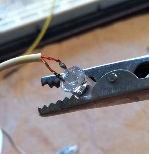
Next, I fit them into the plastic, and soldered the wires:
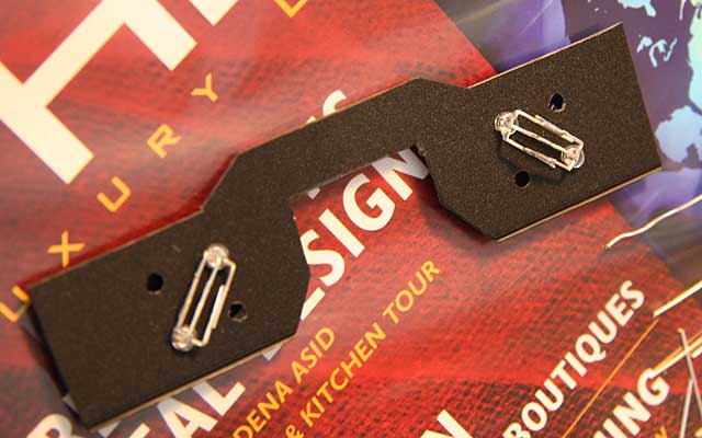
Be careful to solder as quickly as possible, and not to use a high-wattage iron, because LED’s are semiconductors, and can easily be destroyed by overheating.
The inner pairs of LED’s have to be bent a bit differently, so that the leads don’t touch and short out w/ the outer pair of LED’s.
In my case, they were the blue LED’s. Note that the LED’s w/ the extra bend actually go on the inside, so I had to take the first pairs out first. Here’s what they look like up close. Although the inner and outer wires look like they’re touching, there’s a tiny clearance. Here’s what it looks from the other side:
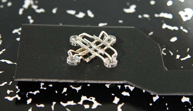
I know, I know, the holes are a bit off, but it’s accurate enough.
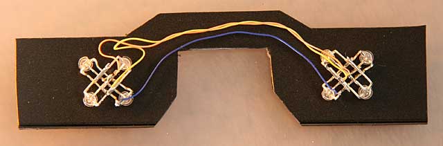
Next, I connected up the wiring. Since my goggles are wired up for CG, the center leads (the cathodes) of all of the LED’s are wired together. The anodes of each color are all wired together. NEEDS PIC OF TRS WIRING HERE
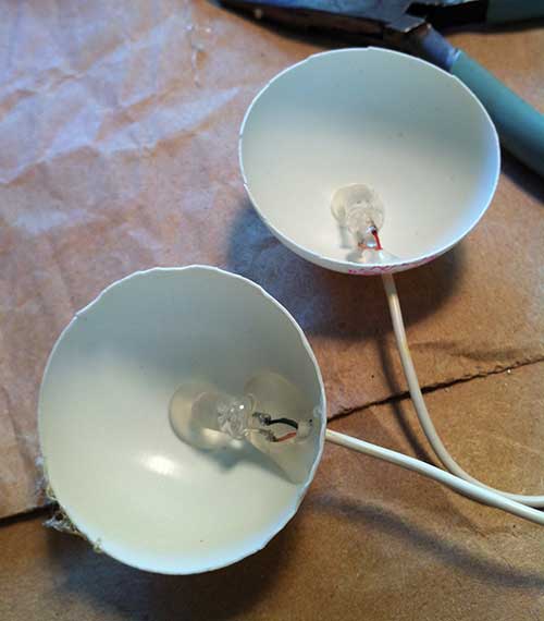
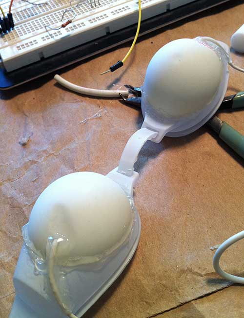
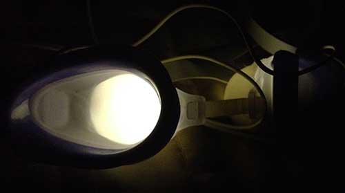
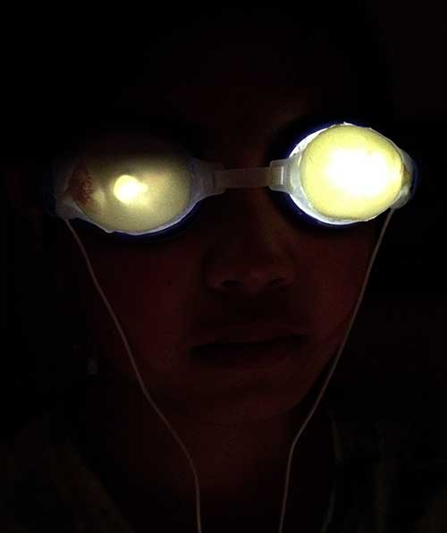
Testing …
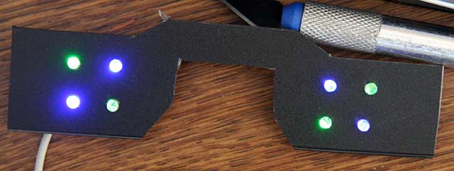
Left channel only