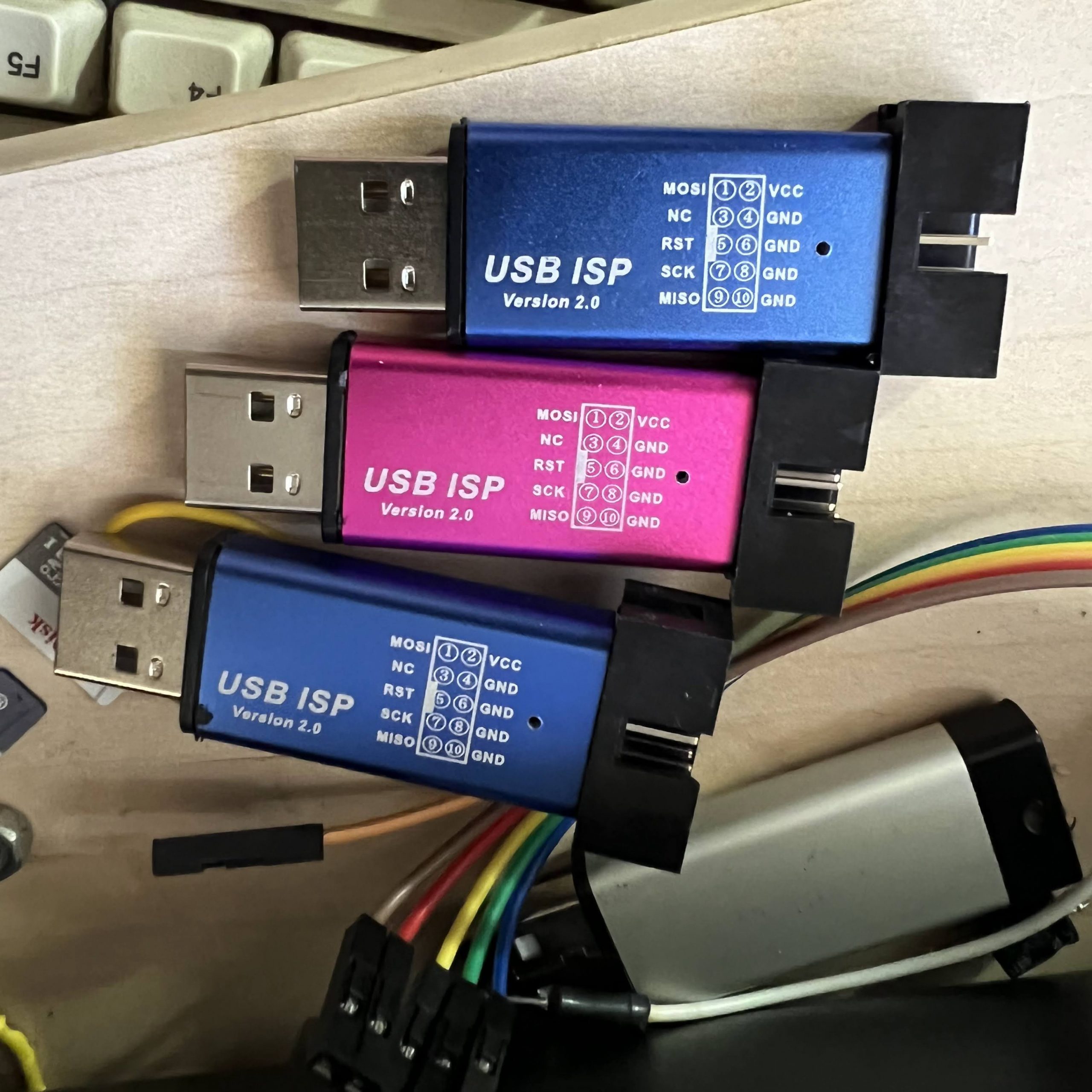
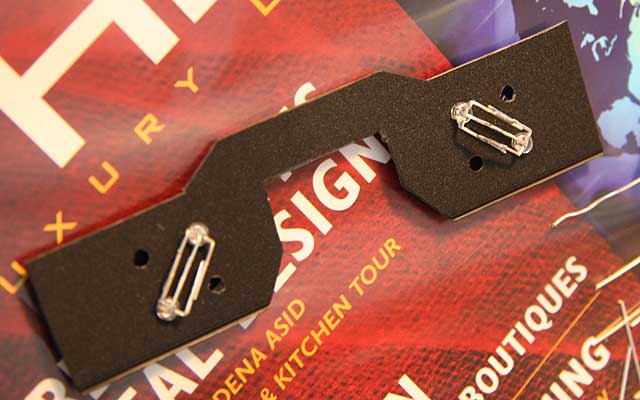
I recently ordered some USBasps from Amazon, which looked interesting, because unlike the typical USBasps, which are just bare PCBs, these had metal cases:
They are also common on AliExpress.
Unfortunately, when I plugged one into my computer, it detected as a USBHID device with VID=03EB and PID=C8B4, rather than as a USBasp. I tried overriding the USBHID driver on my Windows 10 machine, but that didn’t work.
Thankfully, after doing a bit of searching on the Internet, I found that others had encountered the same problem, and had found a solution. It seems that the firmware loaded into these things from the factory is proprietary, and require that you use the manufacturer’s janky software … it’s not AVRdude compatible!
Thankfully, the hardware is actually compatible w/ USBasp firmware with a minor tweak, and you just have to flash it with modified USBasp firmware.
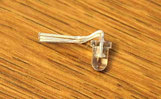
I have a bunch of real USBasps, so I used a USBasp to convert the fakes into real USBasps! In order to program it, slide off the metal case. Next need to connect a jumper across the two holes labeled –> UP <–. The jumper enables programming of the onboard ATmega88V. Then plug it into your other USBasp or other ISP programmer, using the 10-pin ICSP cable:
So where do you get the special firmware? GreenPhotons has graciously compiled a modified firmware for us. Next use AVRdude to program the USBasp firmware into our target:
You can use any ISP you already have, if you don’t have another USBasp. Just substitute the programmer in the -c parameter (e.g. -cusbtiny for a USBtiny). If you don’t have another ISP programmer, you can use an Arduino. This guy shows you how, as well as another way to get firmware.
If you get the following error, then your USBHID ISP has an ATmega88P instead of an ATmega88V
D:\hacking\arduino\USBasp\convert_usbhid>avrdude -cusbasp -pm88  -Uflash:w:20161227_mega88_usbasp.hex

avrdude: AVR device initialized and ready to accept instructions

Reading | ################################################## | 100% 0.02s

avrdude: Device signature = 0x1e930f
avrdude: Expected signature for ATMEGA88 is 1E 93 0A
         Double check chip, or use -F to override this check.
Just substitute -pm88p for -pm88 in the avrdude command line:
Commercial mine machines are quite expensive, and often inflexible, containing only a few canned programs. In this series, I will show how to build an infinitely reconfigurable photic-stim mind machine on the cheap. Rather than build an oscillator circuit, we will drive our mind machine with computer-generated waveforms via an audio player. You can use your favorite audio playing program on your computer, or a portable MP3 player.
UNDER CONSTRUCTION: I still have a ways to go w/ filling in details, but I thought I would at least throw up the article first, since it might take me forever. Please pardon the omissions.
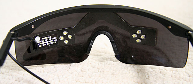
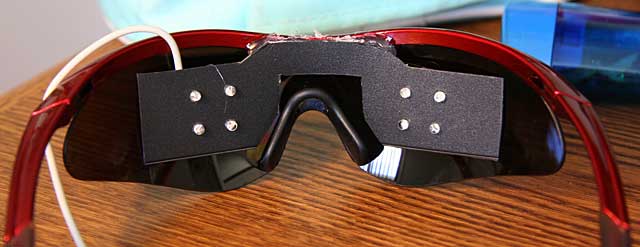
Photic-stim goggles cost typically more than $50, but they’re typically built with only <$1 worth of LED’s, and some cheapo ski-type sunglasses.
Below are the lightframes which came with my Sirius AVS machine, which I purchased from MindModulations.com.
Note how they are just as I described above, a cheap pair of ski-type sunglasses, with 8 LED’s wired into a sheet of black plastic. The plastic is attached to the sunglasses with double stick foam tape.
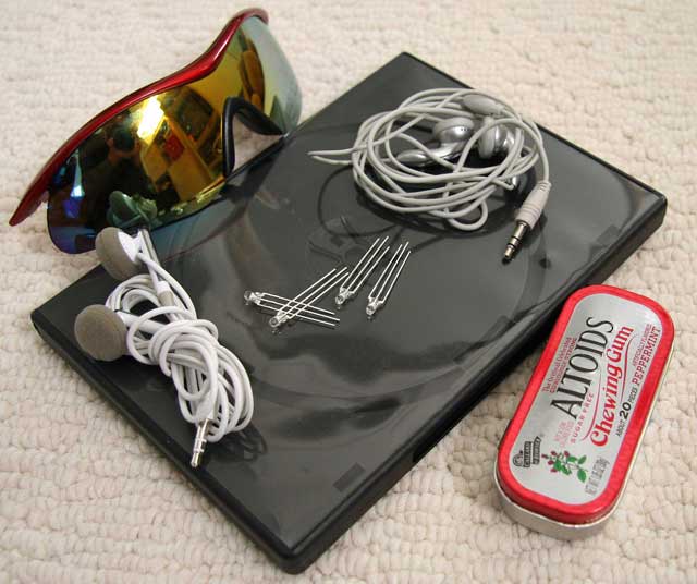
Below are the materials we need for our project:
Bill of Materials (BOM)
Ski goggle style sunglasses. I purchased this pair for under $10
Stereo wiring with 1/8 in phone plug. A cheap pair of earbuds from a local 99 Cents Only Store is perfect for cannibalizing.
Thin, flexible black plastic sheeting. A spare DVD case courtesy of junk mail from AOL will do fine.
LED’s. The type and number of LED’s is up to your own taste. Since my design uses the black plastic sheet insert, I picked 3mm LED’s… they need to be small enough that they won’t bump into your eyes when you’re wearing the goggles. If you want to drill directly into the goggle lenses and eschew the plastic sheet, you can use bigger LED’s. I bought my LED’s from UniqueLEDS.com. They have an extensive selection, and list detailed specs for the LED’s, including brightness. SUPERBRIGHT
Not pictured is a few inches worth of hookup wire. I had some kynar-insulated 40AWG wire wrap wire laying around, which was perfect, due to its extremly thin diameter.
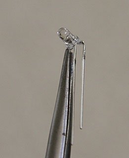
How many LED’s you use is up to you, but the minimum is two, one for each eye. I decided to use 8 … 4 for each eye. Also, I used two different colors, green and blue, on alternating diagonals. Note that my LED’s have 3 leads instead of the usual two. This is because I had a wild idea of using bicolor LED’s so that I could get different color combinations, but I’m not very sensitive to the colors, so I decided to hook them up like one-color LED’s. There are various recommendations on the web for color selection. Personally, I like the bright white LED’s that my Sirius frames used, but I decided to experiment with colors on this set.
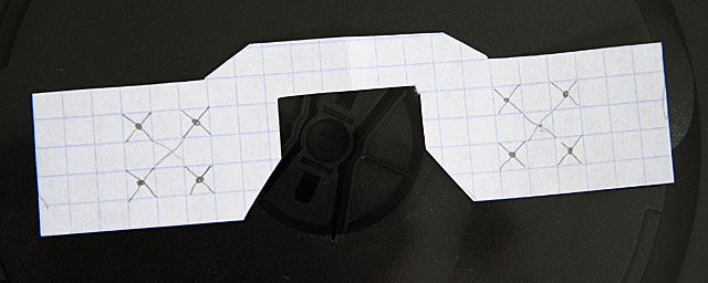
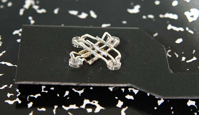
First, cut the black plastic which will support your LED’s. Ask I said above, you can skip this step, and drill directly into the lenses, but it will look a lot uglier, since the wiring will be exposed in the front. Also, the drilling method doesn’t let you easily reconfigure the frames if you change your mind about the layout. I used graph paper to make a paper template for my LED layout:
You should lay out the LED’s so that they’re fairly well-centered over your eyes. If you space them out a bit, it will allow for inaccuracy, and eye movement. Note that my layout is rotated 45 degrees with respect to the layout used by the Sirius. My DVD case was soft enough that I could just use scissors to cut out the template, but you may need to use an X-acto knife.You can use a drill for the holes, but I spun an X-acto knife around, instead, and slowly increased the size of the holes until I had a tight fit. (BTW, for the curious, those are not my hands in the photo).
I misaligned one of the holes a bit, as will be apparent in later photos, but it works fine, even though it’s a bit ugly.
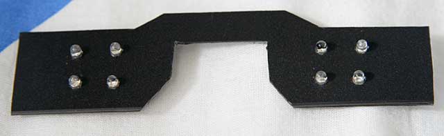
Since we want to keep the LED’s far enough away that they don’t hit your eyes, we need to bend the leads as tightly as possible. I used a pair of needle-nosed pliers, but if you’re careful, you can just use your fingers on the edge of your desk:
Here’s what they look like when they’re done. Since my layout uses alternating colors on the diagonals, I first bent two of the green LED’s. Then, I bent another pair of green LED’s in the opposite direction. The opposite polarity of the bending is important, because the LED’s are hooked up in parallel. Here’s what they look like before I cut the leads:
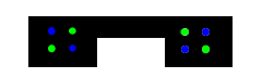
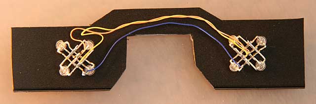
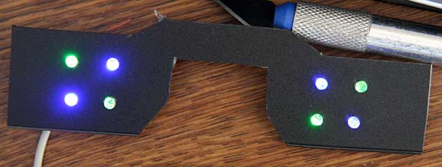
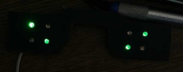
Now, the wiring and layout of the leads will vary considerably, depending on how you want your LED’s to behave. The lightframes I built behave very differently from the Sirius lightframes, which utilize the industry standard wiring. In the Sirius setup, all 4 LED’s on a particular side light up synchronously. The left side responds to the left channel, and the right side responds to the right channel, so the two sides can be controlled independently. This is an example of how they can blink:
My design mimics the IC/D setting of TC-Softworks lightframes, hooks up each pair of diagonals together. The greens respond to the right channel, and the blues respond to the left channel. Therefore, both eyes are always lit, but the intensity and color can vary.
You can use your imagination to come up with your own unique design.
If you are building your goggles to work with a particular mind machine, be aware that there is another variation in the wiring, which affects the compatibility. All of the schematics I have shown up to now have used Common Ground (CG) wiring, where the cathodes (grounds) are all tied together. Some machines, such as my Sirius, use Common Power (CP) wiring, where the anodes (power) are tied together. Before wiring up your goggles, make sure you know if you need CG or CP wiring. As it stands, the goggles I built are incompatible w/ my Sirius.
You must also be aware that which polarity you choose will affect the polarity of the signals that you use to light up your goggles. CG goggles light up when the signal is positive, and CP goggles light up when the signal is negative. Thus, if we use the following signal, CG goggles would light up in the first half of the cycle, and turn off in the second half, where the signal goes negative.
On the other hand, CP goggles will do the opposite, and be dark in the 1st half cycle, then light up in the 2nd half cycle.
Next, I fit them into the plastic, and soldered the wires:
Be careful to solder as quickly as possible, and not to use a high-wattage iron, because LED’s are semiconductors, and can easily be destroyed by overheating.
The inner pairs of LED’s have to be bent a bit differently, so that the leads don’t touch and short out w/ the outer pair of LED’s.
In my case, they were the blue LED’s. Note that the LED’s w/ the extra bend actually go on the inside, so I had to take the first pairs out first. Here’s what they look like up close. Although the inner and outer wires look like they’re touching, there’s a tiny clearance. Here’s what it looks from the other side:
I know, I know, the holes are a bit off, but it’s accurate enough.
Next, I connected up the wiring. Since my goggles are wired up for CG, the center leads (the cathodes) of all of the LED’s are wired together. The anodes of each color are all wired together. NEEDS PIC OF TRS WIRING HERE
Chris H built and sent me a revised board for LeafCAN. The V2 board puts all of the components on the back of the board, instead of facing the LCD. By also eliminating all of the header pins (except for the ones used to connect the LCD), the assembly becomes considerably thinner than V1:
Below are my V2 and V1 meters side-by-side. The V2 meter is on the left:
The new circuit allows software control of the backlight, so I changed the firmware to turn off the backlight 5 seconds after CAN bus activity stops, and turn it back on when the activity resumes.
I also added a new feature, which I call “fixed fuel bars.” Recently, I noticed that the 12-segment fuel bar display in the Leaf’s dash is misleading and inconsistent. Even as your battery degrades, it always displays 12 bars at 100% charge, regardless of how much energy your battery can store. Over the course of 10K miles and 1 year of driving, my range has been dropping. Lately, I’ve been caught off guard, almost running down to turtle on 2 occasions, on a 66 mile drive that used to be easy. My SOC at 100% has dropped from 270 to 255 (I never got 281, even when the car was new). Another thing is, the car often only has the range with 3 bars remaining that I used to get with 2 bars remaining. So, I decided to make a new fuel display, which directly links the SOC and “fuel.” On my fuel scale, 13 = 281 gids, and the transition from 0 -> 1 is at 24 gids, which corresponds to Very Low Battery. The number is displayed with 1 decimal point. I put the zero point at Very Low Battery, because when the charge gets this low, we really need more precision, and should be using raw SOC values. Unlike the fuel bar display in the dash, the first bar contains as much energy as the rest.
I find it more convenient to use this new fuel gauge than SOC %, because I can easily do the calculations in my head while driving. When driving, I’ll count the number of miles for it to drop by 1, and then multiply it by the remaining count. For example, saw the car goes 8.3 miles when the “fuel” drops from 11.1->10.1.” Then I estimate that I can comfortably drive 80 miles given the current driving conditions.
Worst case for me is about 5 miles per fuel point, so when I want a conservative estimate of range, and I know I’m not going to be climbing any long, steep hills, I can just multiply the fuel number * 5 to estimate range.
In the photo below, you can see I’ve rounded the corners on the new case, and the slimmer design looks nicer. Also, I’ve switched to a 4-conductor white telephone cable, which is slimmer, and thin enough to squeeze in the gap between the left dash & the body. I’m able to use only 4 conductors, because this build is hardcoded to use only the EV bus, so the only wires I need are power/ground/CANH/CANL.
The top line displays: remaining pack KWh/SOC in gids/remaining fuel
The bottom line displays: pack voltage/instantaneous amps/instantaneous power draw KW (pack voltage * amps / 1000).
As usual, the latest code is available on github, and you are welcome to modify the display code to suit your own tastes.
Thanks to wiltwong and Markus Lange, I have added support for Arduino Mega and Leonardo to the Colorduino Library. Markus also helped to clean up the code a bit for Arduino 1.x. I have added the ColorFill() function to the ColorduinoObject class, as well, so you don’t have to copy it from ColorduinoPlasma.pde.
I was not fast enough to get an order in for a Raspberry Pi on launch day. Fortunately, a kind friend of mine thought of me, and bought an extra one for me. I received it yesterday, and printed this case:
The case I made is a copy of HansH’s excellent Raspberry Pi case, modified with a slot that added on the top to accomodate access to the GPIO pins. I uploaded it to Thingiverse: Raspberry Pi Case with GPIO Access. Here’s the first sucessful boot of my Raspberry Pi:
It looks so tiny sitting in front of my 52″ plasma. I was pleasantly surprised to see it boot up at full 1080 resolution. At first, I thought the HDMI port was bad, because it didn’t work with a cable that I know is good, but it turns out the Pi is just picky about HDMI cables. I swapped in a different one, and it worked. Now, I have a lot of reading to do… yet another gadget to play with…
Another tweak today, I added instantaneous battery power consumption in KWh to the second line of the display. In order to make room, I had to do away with the V and A characters after the voltage and current draw. Here is the new display:
The top line, from left to right, contains Battery Pack Remaining KWh, SOC (“GIDs”), SOC % (GIDs/281*100), and Remaining Fuel Bars.
The bottom line now contains Battery Pack Voltage, Battery Pack Current Draw (Amps), and Battery Power Consumption (Pack Voltage * Pack Amps).
For users who prefer the old display, I added:
#define SHOW_KWH
#define SHOW_KW
If you comment out both lines, the display will be the same as v1.0, but with the smoothing that was added in v1.1.
I wrote a Colorduino library for Arduino. It handles initialization and double-buffered drawing on ITead Studio’s Colorduino. It is also compatible with Itead’s Arduino RGB Matrix driver shield. Included with the library is a sample sketch to show how to use it, ColorduinoPlasma, which draws a pretty plasma on an 8×8 RGB matrix.
To install the library, download the zip file (see below), and copy libraries/Colorduino to your arduino sketchbook/libraries/Colorduino. If you are already running the Arduino IDE, you must restart it before you can use the library. You can then run load ColorduinoPlasma.pde demo.
To include the Colorduino library in your own sketch, just
#include <Colorduino.h>
Then your setup() function needs to just call two functions for initialization:
void setup()
{
Colorduino.Init();
// compensate for relative intensity differences in R/G/B brightness
// array of 6-bit base values for RGB (0~63)
// whiteBalVal[0]=red
// whiteBalVal[1]=green
// whiteBalVal[2]=blue
unsigned char whiteBalVal[3] = {36,63,63}; // for LEDSEE 6x6cm round matrix
Colorduino.SetWhiteBal(whiteBalVal);
}
Colorduino.SetWhiteBal() is used to adjust the white balance. You can put
ColorFill(255,255,255);
in your sketch to test the white balance by drawing a white screen. Then adjust whiteBalVal until your screen approximates white.
The origin of the screen, (0,0) is at the bottom left corner. The off screen buffer can be accessed either pixel by pixel:
Colorduino.SetPixel(x,y,r,g,b);
or by direct manipulation. The screen buffer is arranged by row. For instance to set all of the pixels in the second row to the same color:
ITead Studio kindly sent me a Colorduino for beta testing. The Colorduino was inspired by SeeedStudio’s Rainbowduino LED Driver Platform. Its form factor is very similar to that of the Rainbowduino, and the layout of the connectors was intentionally designed to mimic the latter. Both boards are based on the ATmega368 MCU, and are Arduino compatible. The principal difference between the platforms is that while the Rainbowduino is based on 3 MBI5168 constant current sink drivers and a M54564 darlington source driver, the Colorduino pairs the M54564 with a single DM163 constant current driver. By using the DM163, the Colorduino gains three 8+6-bit channels of hardware PWM control of the LED’s freeing up the MCU from having to implement it in software. This gives the ATmega more CPU bandwidth for performing other tasks. In contrast, the Rainbowduino implements three 4-bit channels of software PWM. One important limitation, however, is that the DM163 only has 24 channels… this is just enough to buffer one line of 8 RGB LED’s (8×3 = 24), rather than an entire 8×8 RGB matrix. So while the MCU is freed of the software PWM task, it still has to constantly scan line by line to refresh the screen. However, the row scanning takes up considerably less CPU bandwidth than having to also handle software PWM, and ups the bit resolution of each color channel to 8+6 bits.
The extra 6 bits of data in each color channel allows software control of the relative PWM brightness, so that the user may not have to resort to using external resistors to adjust relative channel current (which is also supported by the DM163, but the Colorduino, unlike the Rainbowduino, does not have onboard potentiometers for adjusting individual RGB current). The Colorduino is quite compact (the same size as the Rainbowduino), being slightly smaller than the 60x60mm common anode RGB LED for which it is designed as a direct plug-in.
The Colorduino is pictured below:
Behind the Colorduino is my LEDSEE 60x60mm RGB matrix.
Below is a top view:
Keep in mind that this is a beta board, and ITead is still tweaking it. One problem I found is that the ICSP header doesn’t have enough clearance for me to plug in my USBtinyISP. The sliding switch is for selecting betwen onboard regulator (for use with 7-12V power supplies) or a regulated 5V input. As you can see, the board is a bit rough looking, with crooked parts and flux residue. ITead Studio has assured me that the ICSP header will be moved to a better location, and that the production boards will be cleaner. Also, although the beta boards have an ATmega168, the production boards will use the ATmega368. Note the 8-pin headers for easy daisy chaining. When multiple boards are snapped together, a host can address each one individually via I2C. The power is also easily interconnected between the boards via the dual 4-pin green screw terminals. Bottom view below, snapped into the 8×8 RGB matrix:
From the photo above, you can see how compactness of the Colorduino. It’s slightly smaller than the RGB matrix. NOTE: The bypass cap yellow added between VDD and GND will be moved to the PCB before production. One downside of the Colorduino (which is shared by the Rainbowduino), is the dearth of I/O pins left over for the user. TX/RX/SCL/SDA are all you have to play with, and some or all of them may needed for communication. If you need more I/O, a likely scenario will be to connect the Colorduino to an Arduino via I2C. Kind of a shame, given that the hardware PWM frees up considerable CPU bandwidth for other functions.
Below is the Colorduino running a plasma demo. Notice my Arduino Duemilanove attached on the left, supplying power. Since I can’t use ICSP, I’m using the Duemilanove, which you can see on the left, as a serial programmer. I would like to get my USBtinyISP connected, so I regain some of the ATmega168’s small memory space by getting rid of the bootloader.
Finally, below is a rather horrible video of it running ITead’s demo code, followed by my plasma demo. There is absolutely no flicker when viewed with the naked eye, what you see in the video is just an artifact.
The photos and video don’t do it justice. The Colorduino supplies considerable drive current, making the matrix blindingly bright. The LEDSEE 8×8 matrix is gorgeous. I wish I could capture it properly in my photos. I chose it because it was cheaper than the alternatives I found, while having the brightest output. However, it took 2 weeks for LEDSEE to ship it out, and in total, it took over a month for me to receive it. I sent them several inquiries about my order, which they completely ignored. In light of their bad (nonexistent) customer service, I doubt I will deal with LEDSEE again. ITead, on the other hand, has been quite responsive in their communications.
Currently, the Colorduino documentation is rather sparse. ITead has a blog entry where you can download the schematic, DM163 spec, and their sample Arduino sketch. ITead anticipates that the revisions will be completed and it will be put into their iStore sometime in April. They are targeting a price of about $27, slightly higher than the Rainbowduino. ITead Studio also makes an Arduino RGB LED Matrix driver shield, which is already available for $14.80. When this shield is plugged into an Arduino Uno/Duemilanove, the combination is equivalent to a Colorduino, and uses exactly the same code.
Upon initial testing, the Colorduino appears to be a worthy challenger to the more established Rainbowduino, which has already spawned a dedicated ecosystem of hackers, as well as a wiki full of detailed information. While the Colorduino has a lot of catching up to do, it seems quite capable, I look forward to running it through its paces in the coming weeks, when I use it to implement a large scale 8×8 RGB matrix.
I bought 100 diffused 5mm RGB LED’s on eBay for my upcoming project, an 8×8 RGB matrix. I was extremely impressed by the fast (free) shipping – 7 days, all the way from China! Much to my chagrin, when I started testing them, I found that the vendor had sent me common cathode, rather than the common anode LED’s that I had been expecting. This is a big setback for me, because I was going to use them with the Colorduino that ITead Studio is graciously sending me for beta testing. The Colorduino expects common anode LED’s, so now I have a pile of 100 useless LED’s. Nevertheless, I decided to test them out to find out their brightness, color mixing, and diffusion characteristics.
Andy Rapp has posted a handy setup for testing RGB LED’s on his blog. He wrote a Java program and Arduino sketch, which allows you to interactively control an RGB LED with a host PC. I downloaded his code, and had it running very quickly.
I also built a little 2x2x2 foam box, and put a piece of Grafix .005″ thick matte drafting film on top of it. The LED works fairly well. I’m satisfied with how well the combination diffuses the light.
Andy’s Java app puts up a color picker on the host computer screen, which lets you interactively test out different colors in realtime. You can see the color picker in the bottom right corner of my computer screen. The brightness of a single LED is better than I was expecting, but the color mixing is not. It’s hard to see in the photos, but the red/green/blue components don’t mix that well, and the individual colors are brighter in certain areas. In the photo above, notice how one side of the box is more purple, and the other side is more magenta. This makes it impossible to get a decent approximation of white, even when you compensate for the fact that the 3 colors differ quite a bit in brightness when the same current is passed through them. Below are some more shots. In the yellow shot, I’m raising the box up so that the LED is lined up with the bottom of the box. This makes the light noticeably smoother looking. Note how the light is not centered in the box, even though I have the LED pointing perfectly vertical. I may have to make minor adjustments when I build the real matrix.
It looks bright enough that I may be able to get away with just using 1 LED per cell. I’ll have to see when I get the correct common anode LED’s and the Colorduino to play with.
UPDATE: I did some more testing. In the photo below, the top row is @ 100% brightness, and the bottom row is @ 50% brightness. In the left column (“sidelit”), the LED is centered in the box, but pointing to one of the walls (so the view of the LED through the hole is the side of the LED). In the center column (“centered”), the LED is pointing straight at the and is physically centered in the box. In the right column (bottom), the LED is pointing straight at the drafting film, but aligned w/ the bottom of the box. As you can see, the “sidelit” setup has the best color mixing and is the most even in brightness. The “centered” setup is brightest, but has the biggest hot spot, and the colors don’t mix as well. The “bottom” setup is a bit more even in brightness, but still suffers from uneven color mixing. I’m still undecided about which way to go. What I like about the “sidelit” setup is that it enables the option of making a free-standing matrix that lights up two sides instead of just one. I guess I’ll have to put off the decision making until I get the Colorduino and the common anode LED’s. I contacted the eBay vendor this afternoon, and he says he’ll rush out the common anode LED’s tomorrow. Hopefully, they will arrive in a week.
Comparison of LED placements - click to see full size