Arduino 1.0.5-r2 for AT90USB1286 and Printrboard

It’s been a few years since I hacked together the copy of Arduino-0022 that’s been floating around the web, which lets you compile and automatically upload Arduino code to an AT90USB1286. This made it a lot easier to develop Arduino code for the AT90USB1286, and in particular to easily modify the Marlin firmware for the Printrboard.

Yesterday, I figured it was high time to add AT90USB1286 support to Arduino 1.0.5-r2. The basic procedure for the modification was to first install Teensyduino, which adds the AT90USB1286 compilation support to Arduino, but only uploads to a Teensy++ 2.0, running PJRC’s proprietary halfkay bootloader. I modified the Teensyduino configuration to also support uploads to targets running the LUFA CDC Bootloader, or via USBtinyISP or USBasp ICSP programmers.

Note that I copy that I modified only runs on Microsoft Windows.
You can download it from github: https://github.com/lincomatic/arduino-1.0.5-r2-at90usb1286
It’s easiest to download it as a zip file: https://github.com/lincomatic/arduino-1.0.5-r2-at90usb1286/archive/master.zip

Once you unzip the archive and launch arduino.exe, you will notice some new entries in the Tools->Board menu:

[USBasp]AT90USB1286
[usbtinyisp]AT90USB1286
[BootloaderCDC]AT90USB1286
[USBasp]Printrboard
[usbtinyisp]Printrboard
[BootloaderCDC]Printrboard

The only difference between the Printrboard and AT90USB1286 entries is that the extraneous USB Type, CPU Speed, and Keyboard Layout submenus are grayed out from the Tools menu.

To load Marlin firmware onto a Printrboard, you will most likely want to use [BootloaderCDC]Printrboard.

Note that unlike my Arduino-0022 hack, the pinMode()/digitalRead()/digitalWrite() functions in version currently only support the pins that are exposed on the Teensy++ 2.0. This is because I haven’t yet had the time to figure out how to add in the remaining AT90USB1286. However, this limitation doesn’t affect Marlin firmware on the Printrboard, because Marlin uses its own fastio functions, rather than using Arduino digital pin numbers and pinMode()/digitalRead()/digitalWrite(). See pinmap.txt for the currently supported Arduino digital pin numbers.

Thanks again to PJRC for Teensyduino. Teensys are a great alternative to Arduino boards.

Marlin Tuning

To get the most out of Marlin, here are a few simple tweaks.

1. EEPROM Settings

By default, Marlin forgets any configuration changes you make via the Mxxx G-codes whenever you reset or power cycle your controller. If you want to remember the settings, so you don’t have to set them every time you power up your controller, Marlin can store them in EEPROM. In Configuration.h, uncomment

#define EEPROM_SETTINGS

EEPROM_CHITCHAT is optional:

//to disable EEPROM Serial responses and decrease program space by ~1700 byte: comment this out:
// please keep turned on if you can.
#define EEPROM_CHITCHAT

You will need to compile Marlin and then upload the modified firmware to your controller in order to take advantage of the changes.

After sending your Mxxx G-codes to Marlin, send M500 to save them to EEPROM.  You can also revert to default (“factory settings”) with M502.

One nice feature of Repetier-Host is that you can use it to set your EEPROM, rather than manually typing in Mxxx G-codes.  Simply go to Config->Firmware EEPROM Settings from the menu.

Personally, I prefer to just set all my Mxxx G-codes as start G-codes in Slic3r, rather than storing them in EEPROM, but most people will probably prefer to use EEPROM.

2. PID Auto Tune

When I first switched to Marlin, I was not at all happy with the temperature control of my extruder.  It was taking a long time for my hot end to heat up, and the temperature was still varying a lot. While the hot bed is controlled using bang-bang (traditional on/off temperature control), the extruder uses a more sophisticated algorithm, called PID, which should yield better temperature stability.

Initially, I tried turning off PID by commenting out

#define PIDTEMP

in Configuration.h.  My hot end heated up much faster, but the temperature was still fluctuating a lot.  I decided to try to get PID working better.  In order to get best performance out of PID, there are some parameters which need to be tuned: Kp,Ki, and Kd.  Configuration.h contains settings for Ultimaker, Makergear, and Mendel Parts hot ends, but I’m using a JHead.  I had no idea what values to use for After doing a bit of googling around, I found out that Marlin has a way for it to automatically calculate PID parameters, G-code M303 – PID relay autotune.  To automatically tune your hot end PID parameters, start with your hot end at room temperature, and using Pronterface, send it the M303 G-code as follows:

M303 S230

The parameter is the target temperature in celcius.  If your target temperature is different, substitute it for the 230.   Marlin will then heat up and cool down your hot end, while taking measurements.  This will take a while.  When it’s done, it will output a message similar to this one:

bias: 103 d: 103 min: 147.98 max: 152.02
Ku: 65.06 Tu: 30.67
Clasic PID
Kp: 39.04
Ki: 2.55
Kd: 149.66

Next, you need to tell Marlin to use the calculated Kp, Ki, Kd values.  If you don’t want to hassle with compiling/reloading Marlin, you can just use the M301 – Set PID parameters P I and D G-code.  Using the my values above, it looks like this:

M301 P39.04 I2.55 D149.66

I simply added the line to my start G-code in Slic3r.  Setting the PID parameters in G-code allows you to change them on the fly for different profiles, for instance, if you like to switch back and forth between PLA and ABS.

If you prefer to hardcode the values as defaults in the firmware, set them as follows in Configuration.h:

#define  DEFAULT_Kp  39.04
#define  DEFAULT_Ki 2.55
#define  DEFAULT_Kd 149.66

3. Acceleration and Jerk

If your printer vibrates a lot when printing at higher feedrates, causing wiggly prints, you can improve the quality without slowing down your prints too badly by lowering the acceleration and/or XY-jerk values. In Marlin, acceleration is specified in mm/s^2. The default is 3000. On my Printrbot, I slowed it down to 1000 with G-code as follows:

M201 X1000 Y1000; // max accel print
M202 X1000 Y1000; // max accel travel
M204 S1000; // default accel for normal moves

You can also change the value in Configuration.h, if you prefer:

#define DEFAULT_ACCELERATION 1000 // X, Y, Z and E max acceleration in mm/s^2 for printing moves

If you have a slow extruder, you can also slow down the retraction acceleration, but generally, there’s no reason do do this:

#define DEFAULT_RETRACT_ACCELERATION  3000   // X, Y, Z and E max acceleration in mm/s^2 for r retracts

3000 is the default value.

The jerk value is also useful, and affects the speed at which Marlin joins two segments. The default XY-jerk value is 20 mm/s.  Lowering the value will slow down the transitions between segments.  This is especially helpful for smoothing out ringing waviness on 90 degree turns.  I found that 15mm/s is a good balance between speed an quality on my Printrbot.  G-code:

M205 X15; // max xyjerk mm/s

Configuration.h:

#define DEFAULT_XYJERK                20.0    // (mm/sec)

There are also values for the z-axis and extruder, but I didn’t need to change them:

#define DEFAULT_ZJERK                 0.4     // (mm/sec)
#define DEFAULT_EJERK                 5.0    // (mm/sec)

When tuning acceleration and jerk values, a handy way to test the effects of your new settings is the Dry Run feature of Repetier Host.  When Dry Run is enabled, the extruder is disabled while printing, so you can observe its motion without wasting filament.

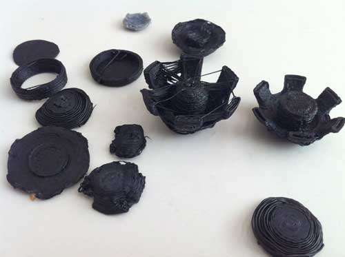
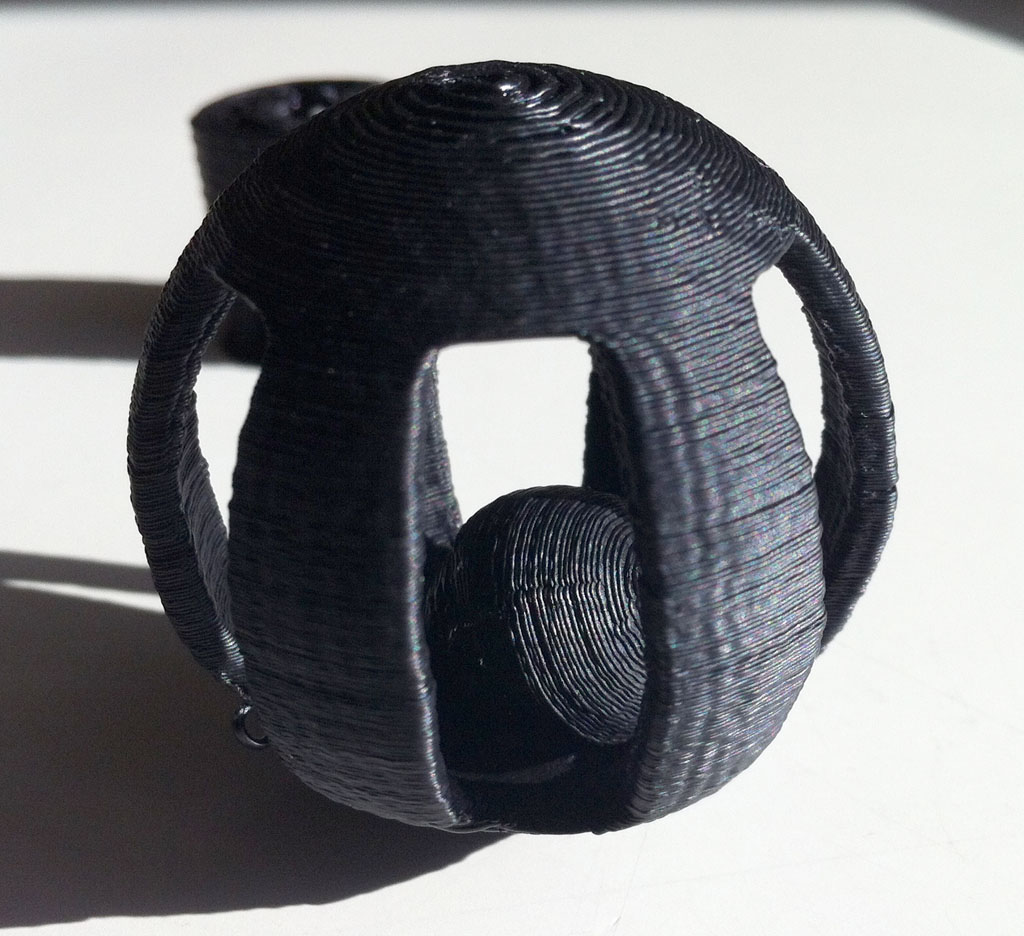
After tuning the acceleration and jerk values my prints are better quality at higher feedrates, without sacrificing too much speed.  Note that depending on your print, the lower acceleration/jerk values will have more or less effect on the total time it takes to complete it.  Prints that have more short segments will be slowed down a bit more.

Even though my discussion was about slowing down the printer, you can also tune the acceleration/jerk parameters to speed things up, if you have a particularly well-tuned bot.

Marlin for Printrboard Updated

I just synced my Marlin branch for Printrboard with the latest code from ErikZalm’s branch. I noticed that there were a lot of changes in the planner, temperature control, etc.  Hopefully, it will be an improvement, rather than breaking anything.  Please report here or on github if you find any anolmalies with the new code.

Download Marlin for Printrboard here: https://github.com/lincomatic/Marlin

Printrbot Build

My Printrbot from the Printrbot’s Kickstarter Campaign was supposed to arrive in February. Unfortunately, due to the huge number of supporters they received, the schedule has been pushed back, and I doubt I’ll receive mine until late May. In the meantime, I’ve been getting antsy waiting for mine to arrive, so I decided to go ahead and build one from scratch. The Printrbot that I ordered is actually the laser-cut model. John Seaber of JDS Labs was kind enough to send me the printed bits and a complete extruder for the RepRap version of Printrbot.

I already had most of the other parts needed to build a Printrbot, except for the threaded rods and miscellaneous nuts and bolts. I had 4 used steppers gutted from laser printers (which I bought from Wildseyed), and a stepper for the extruder plus smooth rods from Epson Stylus Color 600 ink jet printer that has been gathering dust for more than 10 years.  There is a decent Printrbot BOM on printrbottalk’s wiki; a few bits here and there are missing, but it still saved me a lot of time. The nuts & bolts were all easy to find at a local hardware store, except for the M3 screws.  The M3 screws were the only parts I had to buy for which an SAE equivalent simply wouldn’t do, since they had to mate into threaded holes in the motors.  I ended up wasting a whole afternoon going to several hardware stores, and almost gave up, before finally finding them at Ace Hardware.  It’s amazing how difficult it is to buy metric parts in the US.

Since I had already been experimenting with my own variations on Wildseyed’s Hot End, I already had a hot end built and ready to go.  My modifications on Wildseyed’s design are 1) it can be completely dissassembled for cleaning 2) the brass barrel is shorter, has less mass, and screws on 3) I’m using a radial resistor embedded in the aluminum block, rather than attaching an aluminum-cased resistor to the outside.

Unfortunately, the extruder I received was set up for a different mount, so I had to adapt it.  A trip to the hardware store yielded a PVC pipe elbow, that, as luck would have it, had the exact inside and outside diameters to form an adapter for my hot end.  I cut out a small ring, and attached the hot end with M3 grub screws.

One thing I learned while assembling this printer is that LM8UU bearings need precise alignment, or they will bind very badly.  The bearings in the Printrbot’s x-carriage are press fit, which is great for simplicity, but can cause headaches if the parts aren’t printed perfectly.  Initially, my carriage was binding very badly, and would barely move.  Even worse, the LM8UU’s were gouging deep grooves into my smooth rods. This is because of two factors 1) the spacing of the x-carriage smooth rods was slightly different between the left and right sides of the carriage, due to imperfections in the printed rod holders and 2) the holes in the plastic x-carriage piece I received were not perfectly parallel.  After some cleanup of the holes with a rasp in my drill press, I got everything to line up, and the carriage now moves smoothly.

I had a similar problem with the smooth rods of my z-axis.  The rods on the y-axis ride on 2 LM8UU’s which are stacked on top of each other, and press fit into a printed plastic block.  Again, due to minor imperfections in the print, the stacked bearings didn’t line up perfectly, and my z-axis bearings were binding quite badly against my smooth rod.  I was lucky that I was able to pry them out, because they were a very tight fit.  Again cleaning up the holes with a rasp on my drill press fixed the problem.

All in all, there was a maddening amount of tweaking and coaxing involved in getting my Printrbot assembled and calibrated.  My x-motor’s shaft was a bit to short so I had to cut down its mount a bit.  This in turn, caused problems with the alignment of the belt and idler bearing.  The z-motor mount dimensions were a bit off, so the threaded rods were tilted inwards, rather than parallel to the z-axis smooth rods. I had to re-drill the holes to achieve the proper alignment.  The couplers between the z motors and threaded rods didn’t quite fit right, and caused the rods to wobble.  I solved this by switching to aluminum couplers.  The crimp on pins that I bought from Ultimachine didn’t fit into the Molex hoods I bought, so I had to improvise the connections to my Printrboard.

I decided to use CAT-5 for wiring my Printrbot.  It’s cheap and has a jacket, so cabling is tidy.  Since the cable has more conductors than I need, and the gauge of the wires in CAT5 is relatively small, I used one twisted pair for each connection.

I still need to attach end stops, build the hot bed, and get a 12V power supply with higher output to power the hot bed.  In the meantime, I was itching to crank out some test prints.  The problem is that it’s very difficult to get the molten ABS to stick to any cold surface.  I finally decided to try something crazy … print ABS on ABS.  I printed on a piece of the Epson Stylus Color 600 printer from which I salvaged the motor that I’m using for the extruder.  The first object that I printed was a replacement foot for my Vitamix.

My Printrbot is running Marlin firmware, which I adapted to run on Printrboard, and I’m using either Pronterface and Repetier host software, depending on my mood.  Currently, I’m using Slic3r to convert STL’s to GCODE. While calibrating the printer, I found that the carriage and build plate vibrate quite a bit, and the motion is not completely smooth.  This wobbling can be seen in my test prints.  Hopefully, the excessive vibration is due to a modification that I made to the design, as opposed to an intrinsic problem in the Printrbot.  Because my rods came in 3′ lengths, I extended all of the rods from 10″ to 12″ long.

Here is my first print, the Vitamix foot:

I was just happy that it came out well enough to use.  At this stage, there was still a lot of tweaking to do … refining the calibration, adjusting the temperature, tweaking the parameters for Slic3r.  After a lot of experimentation and failures

I am finally able to get some decent prints.  In a future article, I will discuss my current printer settings. I made the mistake of selecting a very challenging object as my second print, Surveyor’s Cat Toy.

Here is my best attempt so far:

I am now in the process of printing an extruder for a friend.  My best print to date is the small gear on the left:

Both of the gears are printed with .2mm layer height.  The only difference is that I slowed down the perimeters from 30mm/s to 15mm/s in order to get rid of the vibration.  Here is my Printrbot attempting to print the large extruder gear:

The print actually failed because 1) my extruder jammed, due to a stray piece of plastic which fell into it and 2) my ABS printing surface started warping too much.  I need to get my heated bed working before I can print large parts.

Running Marlin Firmware on a Printrboard

As of this writing, the official version of Marlin firmware from github does not yet work with Printrboard.  Printrboard is a fork of Teensylu, designed by the folks at Printrbot. Printrboard isn’t yet available for purchase, but since the design is open source, anyone can download it and get the PCB’s manufactured themselves. Sprinter is currently the only RepRap firmware works with Teensylu and Printrboard out of the box.  I am now successfuly running Marlin on my Printrboard.  Below is a video of Printrboard virtually printing a Printrbot with Marlin:

Last month, I submitted an issue with ErikZalm to get the compile errors fixed when compiling Marlin for Teensylu.  The main branch of Marlin now compiles for Teensylu by setting MOTHERBOARD = 8.  Unfortunately, this build setting won’t work with Printrboard, because some of the pins are different.  Also, there is a kill function that Marlin calls if it detects certain things like a shorted thermistor, etc… but it’s not able to send the error messages back to the host, so it looks like your board is just dead.
I think Erik is too busy right now getting V1 out the door to deal with making fixes for a couple of not so popular boards, so I’ve forked Marlin on github with my fixes for making it behave nicely with Teensylu and Printrboard.  You can download it here:  lincomatic/Marlin.
——————————–
For Firmware Hackers Only
For those who want to know what’s special about my branch of Marlin, it has to do with the mappings of the I/O pins.  The code in Marlin has two different ways to access digital I/O pins: 1) the Arduino digitalRead/Write() functions 2) fastio – there are macros and pin assignments in fastio.h.  In ErikZalm’s Marlin branch, the pin numbers are different between Arduino and fastio functions, which leads to confusion and bugs.  What I have done is use the digital pin definitions in Teensyduino’s core_pins.h and updated the pins in fastio.h to match them.  This way, a call to digitalRead(28) is equivalent to _READ(28).
EXECEPTIONS:
  1. in pins.h, analog pins use ADC numbering instead of digital pin numbering.  Therefore, even though B_THERM -> F0/ADC0 and E_THERM -> F1/ADC1, we are using them as ADC pins, so B_THERM=0 (ADC0) and E_THERM=1 (ADC1).
  2. Printrboard uses some pins that aren’t supported by Teensyduino, since they aren’t exposed in the Teensy hardware.  Therefore, those pins aren’t listed in core_pins.h.  I have added them to fastio.h, so they are accessible only with fastio macros.  They are digital pins 46 and 47 see the “//– Begin not supported by Teensyduino
    ” section of fastio.h

EXAMPLES:

XSTEP = physical pin 51. Looking at the AT90USB1286 spec sheet, pin 51 = PA0 (AD0)
in core_pins.h, #define PIN_A0 28
in fastio.h,

#define DIO28_PIN PINA0
#define DIO28_RPORT PINA
#define DIO28_WPORT PORTA
#define DIO28_PWM NULL
#define DIO28_DDR DDRA

so in pins.h, X_STEP = 28

X_MIN = AT90USB1286 pin 9 = PE3
core_pins.h doesn’t have a definition for PIN_E3, because the pin isn’t accessible in Teensy++, so we can’t talk to that pin at all with the Arduino functions.  However, it’s in fastio.h:

//– Begin not supported by Teensyduino
//– don’t use Arduino functions on these pins pinMode/digitalWrite/etc
#define DIO47_PIN PINE3
#define DIO47_RPORT PINE
#define DIO47_WPORT PORTE
#define DIO47_PWM NULL
#define DIO47_DDR DDRE

so X_MIN = 47