WS2812B LED (NeoPixel) Control: Part 1 – Serial Control via 8-bit ATmega (Arduino)

INTRODUCTION

I’ve been laying the groundwork for doing some projects using remote controlled RGB LEDs. My first attempt was Lampduino, which used discrete RGB LEDs, and an ITEAD Colorduino as a controller. In that project, I ran into several pitfalls:

  • though inexpensive, assembly of the LED matrix was very labor intensive
  • the LED’s were rather dim, due to the limited drive capability of the Colorduino
  • the frame rate was slow, due to limited baud rate and RAM
  • while it was scalable, I didn’t like the idea of having to use a separate Colorduino for every 64 LEDs

A few years have passed, and WS2812B LEDs have dropped enough in price enough to get into the range that I feel is affordable. They can be found on eBay and AliExpress very cheaply. Also, they can be controlled without any specialized hardware – all that is needed is one GPIO pin. There are libraries available for many of the popular microcontrollers. Some examples are Arduino, ESP8266, Teensy 3.x, and Raspberry Pi.

HOST SOFTWARE

The other piece of the puzzle is control software. For Lampduino, I hacked uRaNGaTaNG’s mtXcontrol Processing sketch into rgbMtx, but I found Processing to be a very limiting platform, which was hard to debug. This time around, I found a couple of interesting free LED control programs, which are both quite powerful. The first one is Jinx! LED Matrix Control, which runs on Windows only, and the second is Glediator, which is a Java app. Both programs, while free, are not open source. However, they are both powerful enough to do some interesting things.

HARDWARE

I decided to start my experiments with an Arduino Pro Mini clone, because they have a tiny footprint, are cheap (clones are <$2 shipped from China on eBay), and I happened to have some laying around. Also, the Arduino Pro Mini’s ATmega 328P MCU runs at 5V, so no level shifting is required when interfacing to WS2812Bs. Glediator’s creator, Solderlab, has barebones, fast serial client Arduino sketch which can be downloaded at: WS2812-Glediator-Interface. It can run on any 8-bit ATmega-based Arduino such as the Mega, UNO, Deumilanove, etc. The code that outputs the data to the LEDs is written in assembly language, and is thus, very fast & compact. Also, rather than using Arduino’s Serial library, it contains its own very compact serial code. At the expense of a little bit of speed, I decided to generalize it a bit, and add my own packet protocol. My code is on github at: WS2812Remote. The main changes that I made in my version of the code are:

  • Since I didn’t understand the Glediator example’s serial code, I reverted to using Arduino’s built-in Serial library. I’ve tested it with baud rates up to 1000000 and an FTDI cable on a Windows PC, and it works fine
  • I added support for my own packet protocol. Glediator’s serial protocol is extremely simple. Each frame starts with 0x01, followed by the pixel data stream. My simple packet protocol adds an XOR check byte, as well as a few simple commands such as color fill and blanking of the LEDs.

I also wrote a C++ program, called pkt_test, which demonstrates usage of my packet protocol.

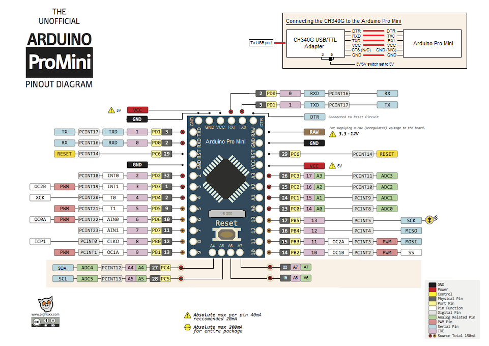
Hookup of the WS2812B LED strand to the Arduino is quite simple. You can use any 8-bit Arduino. First, you must select a data pin to drive the strand. I arbitrarily decided to use pin PD2. For speed and compactness, instead of using Arduino functions to access the data pin, the code refers to the ATmega port and pin numbers, rather than Arduino’s rather arbitrary digital pin numbers. On the Arduino Pro Mini, digital pin 2 = PD2, as can be seen from the following pin mapping diagram:

FIRMWARE CONFIGURATION

So WS2812Remote.h is configured as follows:

#define DATA_PORT PORTD
#define DATA_DDR DDRD
#define DATA_PIN 2

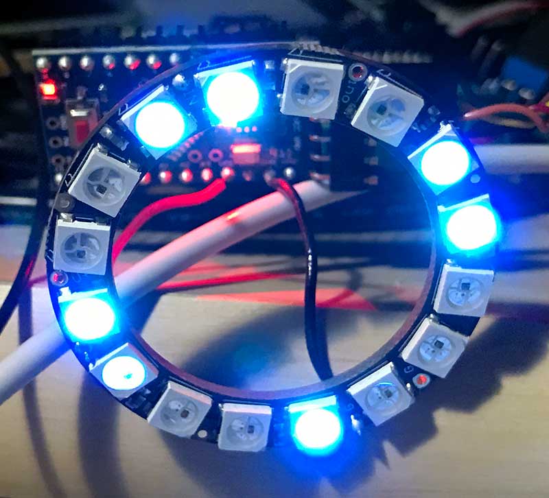
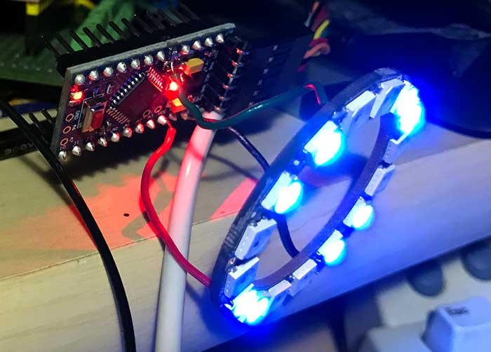
Next, PIXEL_CNT needs to be set to the number of LEDs in your strand. I tested with an Adafruit NeoPixel ring containing 16 LEDs:

#define PIXEL_CNT   16

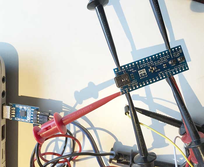
Connect your the data input pin of the first LED of your WS2812B strand to your selected data pin. Adafruit recommends a 300-500 ohm inline resistor to protect from voltage spikes. The NeoPixel ring I used already has a resistor onboard, so I didn’t need it. I connected the +5V and GND pins directly to the corresponding pins on the Arduino. To protect against current inrush when powering it up, Adafruit also recommends connecting a 100uf capacitor between the +5V and GND pins. However, it’s not necessary if you’re just going to power it from USB, which is what I did, since I was only powering 16 LEDs. For large strands, you will need an external power supply to supply sufficient current, as each LED can draw up to 60mA at full brightness. If using an external power supply, make sure to always apply power to the WS2812B strand before the data pin!

HOST SOFTWARE CONFIGURATION

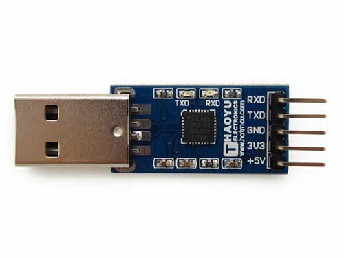
I used the same FTDI cable that I used for programming the Arduino as a virtual com port for sending data to it. When configuring Jinx! or Glediator, select Glediator protocol. For speed, the sketch just receives raw pixel data, and dumps it out to the LED strand, so the data format is in native GRB order.

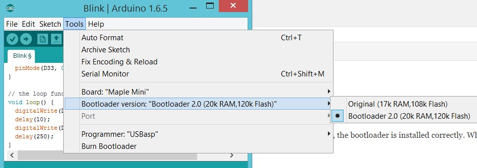
When configuring Jinx! or Glediator, select Glediator as the device type (Jinx!) or output mode (Glediator). Make sure that the baud rate of the corresponding com port matches BAUD_RATE as defined in your sketch. I tested 115200 and 1000000 bps with my FTDI cable, and both worked fine with both programs. It failed at 1250000 bps.

If you want to play around with my packet protocol, the pkt_test code is self explanatory. I tested it with Visual Studio 2015 in Windows 8.1, and g++ in Debian linux 8.2.0. Prior to compilation, set COMM_PORT to correspond to your Arduino’s serial port. Also, confirm that BAUD_RATE in ../WS2812Remote.h matches the value that was used when loading the Arduino sketch. To compile and run pkt_test in linux, use:

g++ pkt_test.cpp serialib.cpp -o pkt_test
sudo ./pkt_test

WIRELESS CONTROL

My first inclination for wireless control was to use Bluetooth, due to its simplicity. The Bluetooth SPP (Serial Port Profile) makes it easy to construct a wireless virtual serial interface between a host computer and the Arduino. This allows you to use exactly the same host software configuration that you would for a direct serial connection to the host. I had an Elechouse EHB Serial Bluetooth Module in my parts bin (very similar to the ubiquitous HC-05), so I decided to try it out.

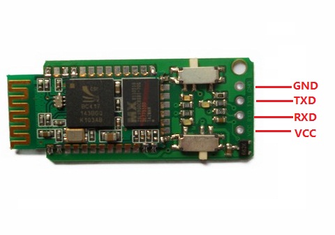
Before using the EHB module can be used, it must be configured with a series of simple AT commands. I hooked it up to my Windows PC with my FTDI cable, and used PuTTY as a serial terminal to configure it. Connecting the EHB module to the Arduino is quite straightforward:

Arduino -> EHB

5v -> VCC
GND -> GND
RXD -> TXD
TXD -> RXD

Pairing the EHB to a host computer creates a virtual serial port for the host software to access. Unfortunately, I was using Windows 8.1 as my host computer, and its handling of Bluetooth SPP clients is rather flaky. Every time I powered down the LED controller, I had to unpair/pair the Bluetooth in order to get the virtual serial port to work properly. While it worked flawlessly when the virtual serial port was functional, ultimately, I abandoned Bluetooth due to the flakiness of Windows’ Bluetooth SPP support. Perhaps Linux can handle it better.

Next: WS2812B LED (NeoPixel) Control: Part 2 – WiFi Control via ARTnet on ESP8266

HowTo: Fix AVRDUDE 6.3/Arduino 1.6.10+ Compatibility Issues with USBasp Clones

I recently upgraded to Arduino 1.6.13, and found that I could no longer program my boards with my Chinese USBasp clone programmer. When the Arduino IDE tried to load the firmware with my USBasp, AVRDUDE couldn’t find my USBasp, and gave this error:

avrdude: error: could not find USB device with vid=0x16c0 pid=0x5dc vendor=’www.fischl.de’ product=’USBasp’

It turns out that the that AVRDUDE 6.3, which is bundled with Arduino 1.6.10+, has timing issues with USBasps. The fix is to replace your libUSB-win32 driver with libusbK v3.0.7.0. An easy way to install libusbK v3.0.7.0 is to use zadig. Download the zadig from

http://zadig.akeo.ie/

Plug your USBasp into your PC.

Launch zadig, and from the menubar, select Options->List All Devices

Next, from the top listbox, select USBasp.

From the Driver selector box, click the up or down arrow key until libusbK (v3.0.7.0) appears.

Finally, click the Replace Driver button.

The screen should look like this:

zadig

You do not have to reboot or disconnect/reconnect your USBasp. After Zadig finishes installing libusbK, AVRDUDE 6.3 will start working correctly with your USBasp.

NOTE: the version of AVRDUDE that Arduino 1.6.x uses is actually controlled by the Boards Manager (Tools->Board->Boards Manager). Even if you have a version of Arduino 1.6.x prior to 1.6.10, if your Arduino AVR Boards by Arduino is version 1.6.10+, it will use AVRDUDE 6.3.

iPhone 6 Over Temperature after Replacing Battery

I just replaced the battery in my iPhone 6. When I attempted to power it up with the new battery, I was greeted with this ominous screen:

iphone_temperature_cool_down_en

which is strange, because there’s no way that it was too hot, since it was just booting up, and it wasn’t even warm in the room where I was doing the work. I was worried that maybe I had broken something during the battery swap, but luckily, it was just bad contact in the battery connector.  It turns out that there is a temperature sensor in the battery, and if it has a bad connection, then the iPhone will think that the battery is overheating. I tried pressing down on the battery connector, but that didn’t work. Next, I simply disconnected/reconnected the battery connector, and it booted up normally. Whew!

So, if you replace your iPhone battery, and it suddenly gets the over temperature warning screen, first check the battery connection. If the warning still won’t go away, but it goes away when you reconnect your old battery, then your new battery probably has a bad temperature sensor.

To replace the battery, I mostly followed the procedure in: iPhone 6 Battery Replacement. However, I slightly modified the procedure:

  1. To remove the screen, I simply attached a suction cup at the end of the screen near the button. Then, while pulling up on the suction cup just enough to make a gap between the bottom of the screen and the back, I slid a guitar pick into the gap, starting at the bottom, and working my way down the edges of the phone, pushing it in gently. You can feel the clips releasing as you push the guitar pick in, and the screen will start to pop out, clip by clip. In Step 6 of the iFixIt instructions, they don’t emphasize the need to release the clips. If you just pull up, you’ll probably damage some or all of them.
  2. I didn’t bother disconnecting the screen. In iFixIt’s instructions, they ask you to unscrew the screen connectors and completely remove the screen. Presumably, this is so that you don’t risk damaging the screen connector, lest you let it swivel back more than 90 degrees from the back. I didn’t bother disconnecting the screen, and instead, held it ajar with my left hand while doing everything else with my right hand. This is because the tiny connectors are very fragile in the iPhone, and I didn’t want to damage the screen connector when disconnecting it, or losing the screws (I had a very bad experience when I was trying to change the battery of my iPhone 4 a few years ago.. the replacement came with a connector that was very tight.. and when I tried to disconnect it, the whole socket broke off the PCB, rendering the iPhone useless).
  3. I don’t have a pentalobe screwdriver, and I don’t intend to buy one. I’ve successfully removed/replaced the screws at the bottom of several iPhones using a Xacto knife as a screwdriver. The tips of my #11 Xacto blades always break off, and the broken off tip fits perfectly into the pentalobe screws.

Now, I’m waiting for the replacement battery to charge up, to see if it’s any good. I always have trouble finding replacement batteries that actually work better than the broken old batteries that they replace. There are a lot of shady suppliers out there who sell used or low quality batteries. I used the free Battery Life app to check the charge cycle count:

IMG_6798

The vendor I bought the battery from claimed that it would have zero charge cycle count, and it has one, but that’s close enough, so I’ll let it slide for now. The capacity is also at 1752/1752, as expected. Of course, these stats could be faked, but at least they appear to be OK, which is some piece of mind. Only usage testing will reveal whether or not I managed to buy a good replacement battery, or another dud.

Update 20160804: So, it turns out that my phone was constantly running hot with the “hand picked” replacement battery I bought on Amazon. I highly recommend that anyone who replaces their battery on an iOS product check it with the free Battery Life app. I found out that the controller chip in the replacement battery was fake. The only stats that would change were the battery voltage and charge leve. The discharge current, temperature, capacity, and cycle count were fixed. After a month of using the battery, the Cycles were still 1! I contacted the seller, and they quickly refunded my money without asking me to send back the defective battery. Buyer beware!

Mini Review: Linksys WRT1900AC

It infuriates me how so many WiFi routers are designed with inadequate cooling. I have a whole pile of routers that got flaky or crapped out after a few years due to overheating. The only ones that are still rock solid after years of continuous service are my WRT54Gs. My Linksys E4200 has been getting long in the tooth lately. On hot days, I need to blow a fan on it, and lately, even colder weather, it slows down to a crawl at random times and needs a reboot. I could try installing a big heatsink in it, but I thought maybe it was time for an upgrade to one of the fancier new technology routers. What most people don’t realize about the latest crop of router technology, such as AC3200, is that unless you upgrade your clients, you’re not going to get performance anywhere close to what these things can do. Most of the devices in my house are 2.4GHz 802.11n and can’t even handle MIMO, but smallnetbuilder had an article which showed that you can get a speed boost with 802.11n on a 802.11ac router. I figured I might as well future proof myself and look for a midrange AC router.

linksys-li-WRT1900AC-9-a

After lots of research on smallnetbuilder’s site, I settled on the Linksys WRT1900AC. This router, built by Belkin, is a nod to the venerable WRT54G, and is designed to be hacked with open source firmware. The specs are pretty good, even in the 2.4GHz band, which is often neglected these days, and I was particularly impressed with the speed of its NAS function, which vastly outperforms anything out there. It has a USB 3.0 port + a combo USB3.0/eSATA port on the back, and lightning fast storage performance. When I received it, I was impressed with the build quality. This thing is a beast! It looks like a WRT54G on steroids, and makes its predecessory look like a toy. Big & beefy and heavy. I specifically got the V1 because it has a built in cooling fan which kicks in only when necessary (which isn’t very frequent, due to its gigantic heatsinks). The later V2, also known as the WRT1200ACS, no longer has a fan. This is not going to be a full review of the WRT1900AC, but only a synopsis of my experiences trying to get decent 2.4GHz throughput out of it.

I really wanted to like the WRT1900AC. It is a thing of beauty, and I spent quite a few hours trying to tweak it, but to no avail. Despite the 90Mbps 2.4GHz LAN to WAN downlink throughput measured by smallnetbuilder, I was not able to get more than about 30Mbps downlink out of any of the devices in my house, even when sitting only a few feet from the WRT1900AC. This is only about half what I get out of my old E4200, which works as fast wirelessly as it does through Ethernet, maxing out at almost 60Mbps, which is the speed of my Time Warner cable service. No amount of tweaking over two days (about 6 hours of mucking with it) could speed up the 2.4GHz downlink performance. I scoured google for tweaks and even tried OpenWRT. I figured that I could figure out to get more speed out of it with OpenWRT’s tweakability, but it actually got slightly slower.

Although the speed with a very strong signal was only half as fast as my E4200, at the edges of my house, where the signal was weak, the WRT1900AC performed admirably, giving not only better throughput, but also being able to actually function at distances where the E4200 signal was completely dead. This left me in a dilemma, because the extended range is actually pretty useful to me. Also, for some reason, the storage performance came up quite short of what was tested by smallnetbuilder. I have a Seagate 2TB USB 3.0 drive, which is normally connected to a hacked Pogoplug E02 running Debian linux. The Pogoplug only supports USB 2.0, and doing a file copy across the network on Windows 8.1, I the maximum throughput I get is about 11MBps. Disappointingly, when attached directly to the USB 3.0 port on the WRT1900AC, the throughput topped out at a measly 4MBps. This was the last straw for me.

The 5GHz wireless performance on the other hand, was terrific. It easily saturated my 60Mbps downlink. But I can’t just switch to 5Ghz, because its range is too short in my house, and the signal drops out in some of my bedrooms. Also, not all of my devices support the 5GHz band. So, with a heavy heart, I decided to return the WRT1900AC. Just as I suspected, upgrading to the fancy 802.11ac router doesn’t necessarily help performance with 802.11n clients. In fact, looking at smallnetbuilder’s testing, lots of the latest and greatest routers put less emphasis on 2.4GHz performance, so if like me, you don’t have any 802.11ac clients, you should save your money and buy something cheaper. As for me, I’m going to try hacking a temperature-controlled fan into my old E4200, and see if that makes it more stable.

Test & Review: GOPHERT CPS-3205 0-30V/0-5A Bench Power Supply

Banggood.com recently had a special on the Gopher Technology CPS-3205 bench power supply. After searching for reviews, which were generally favorable, I decided to get one for $42.99 including shipping. At this low price, I figured it was worthwhile if it worked at all. The unit is small, fanless, and appears well-constructed. What convinced me to try it was Voltlog’s exhaustive video review of the CPS-3205C, which is a more expensive version with active PFC:

I am not able to use the CPS-3205C, because it only works on 240V, unlike the CPS-3205, which is dual-voltage 120/240V.

Upon unboxing, my initial impression of the CPS-3205 was very good. The unit is quite compact, nicely built, and easy to use. One trivial but annoying defect, however, is that the front panel meters are mislabeled. The voltmeter (on the left) is labeled A and the ammeter (on the right) is labeled V:

cps3205

I can’t imagine how such a glaring error could have happened. The photos on Gopher’s website, and most photos from various vendors have the meters labeled correctly:

CPS-3205

I started to wonder whether Banggood was selling counterfeits, also because mine is labeled GOPHERT rather than GOPHER. However, my fears were laid to rest when I found this photo on Gopher’s own website:

CPS-6003s-F

There are definitely genuine devices out there labeled GOPHERT and with the V and A reversed.

One important attribute of the CPS-3205 is that it doesn’t suffer from voltage transients at power up and power down, which can fry an attached circuit, unlike another cheap power supply I was considering, the PS-305D. Here is a test of the PS-305D’s nasty startup transient: Quick test of the PS-305D PSU. Although Voltlog’s testing shows that the CPS-3205 doesn’t suffer from startup voltage transients, there’s even a second layer of protection. By default, the outputs are disabled when it’s powered up. The ammeter displays OFF, and you must press the ON/OFF button on the front panel to enable the output. This further assures that the power is already stable by the time it reaches your attached circuit. Note that the ON/OFF button only controls the output. The main power switch is on the back of the unit. If, for some reason, you prefer to have the output enabled a power on, you can toggle this feature by holding the ON/OFF button depressed for 5 sec. If the ammeter displays dOn, then the output is enabled at power on, and if it displays dOF, then it’s disabled at power on.

The CPS-3205 has over current, over voltage, and over temperature protection, so it’s pretty robust.

I am not going to go into detail on operation of the CPS-3205, because it’s easy to read in the manual, and Voltlog demos it in his video. Suffice to say that the adjustment knob is very handy, because every time you press it, it shifts to a different digit to adjust, making it very fast to do fine or coarse adjustments. The LOCK button locks the adjustment knob and ON/OFF button from changes, and a nice feature is that it’s persistent even if you power the unit off/on.

WARNING: One attribute that’s not clearly stated in the manual is that in constant voltage (CV) mode, the current set in the constant current (CC) mode is an upper limit for the current that can be output. So, for instance, when the voltage is set to 25.00V and the current is set to 100mA, no more than 100mA can be output, so the output voltage will drop if you attempt to draw >100mA. I found this out the hard way, because mine had the current set to 000mA when I received it, so the output was zero in CV mode. I thought the unit was defective, as shown in my video:

After I played around with it some more, I realized that I had to switch it to CC mode and turn up the current before it would output any voltage.

Accuracy

I tested the accuracy of the CPS-3205 against a TES 2208 DMM. This TES meter has been my workhorse for the past 35 years or so, and has never been recalibrated. It’s no Fluke, but in my testing against other meters it’s been pretty good. That being said, I haven’t tested its accuracy in well over 15 years.

Out of the box, I tested a few random voltages in CV mode, and they were spot on. However, the ammeter displayed 5mA even when no current was flowing. Before running the tests below, I calibrated the CPS-3205 against the TES 2208 DMM, following the procedure at the bottom of this article. In the tables below, the readings are all shown to their maximum resolution.

The performance in CV mode was quite impressive, tracking to within .1V, and well within its rated spec of <=0.3% + 10mV.

Setting Panel Reading TES 2208 DMM
 00.01 00.02 .011
 00.05 00.05/00.08 .052
00.10 00.10 .101
01.00 01.01 1.006
05.00 05.00 5.01
05.25  05.25  5.26/5.27
10.00 10.00 10.03
 20.00 20.00 20.0
30.00 30.00 30.0
31.00 31.00 31.0
32.30 32.30 32.3

Generally, the voltage reacted to setting changes within a second, but when I dialed it down from 28.00V to 00.01V, it seemed like it took about a minute to ramp down and finally stabilize. Interestingly, at low voltages <=.10V, even though the panel meter displays on the high side, the actual output is actually quite a bit more accurate.

In CC mode, the performance was not as impressive, but within the rated spec of <=0.3%+20mA.

Setting Panel Reading TES 2208 DMM
001 005 5.7
005 009 9.7
10 15 14.8
20 23 25.1
50 53 55.1
55 56 66.8
60 65 66.8
70 75 77.0
80 90 87.2
100 104 105.3
180 185 187.2
190 197 197.3
200 207 .20
250 254 .25
1.00 1.00 1.00
1.20 1.20 1.20
1.21 1.21 1.21
1.22 1.22 1.22
2.25 2.25 2.25
3.25 3.25 3.25
4.00 4.00 4.00
4.05 4.05 4.05
5.00 5.00 5.00
5.10 5.10 5.10

While CC mode’s accuracy isn’t very good  it’s still within its rated spec. The .3%+20mA accuracy makes it basically useless at low currents, so  don’t use it for tiny loads, such as 20mA LED’s. The lower currents is where the PS-305D is a better performer.

I didn’t bother testing output ripple, because the accuracy of my CPS-3205 was very similar to that of Voltlog’s CPS-3205C, so I’m going to assume that the output ripple is similar. Also, I am not going to post teardown photos, because Voltlog’s video already goes over the innards of the CPS-3205C in quite some detail.

Summary

I am impressed that such an inexpensive piece of Chinese equipment is of such high quality. The CPS-3205 is well mode, easy to use, and surprisingly, comes from the factory fairly well calibrated. The user interface is well thought out.

Being a switch mode supply, it is light, compact, and quiet. Even though it’s fanless, it runs cool at the currents I tested.

One quibble I have is that the binding posts are in the rear of the unit. I wish that they were on the front panel, so I wouldn’t have to reach behind it. Also, the binding posts are lacking a hole drilled into the bolt for easy insertion of wires, and I wish the standoffs were a bit higher, so that they stood a bit farther away from the case.

The CPS-3205 not accurate enough for lab use, but for general hobby use, the performance is pretty impressive, as long as you can live with .3%+20mA accuracy on current control. It’s a great buy for the price. Currently, it can be had for <$50USD if you search around. It’s too bad that the current control isn’t better <100mA. It would have been nice to have the functionality to be able to run it between 5-25mA.

For those who want to re-calibrate the unit, it is easy to do, and the procedure is listed below.

Calibration Procedure

WARNING: ONCE YOU ENTER CALIBRATION MODE, YOU MUST COMPLETE THE ENTIRE PROCEDURE. IF CALIBRATION MODE IS ABORTED BEFORE COMPLETION, THE UNIT WILL ALWAYS DISPLAY ECP/ECP(OCP) AND BE NON-FUNCTIONAL UNTIL YOU COMPLETE A CALIBRATION CYCLE:

eclecl

A user has reported below that attempting the calibration procedure on a CPS-1610 resulted in the display getting stuck on ECL/ECL. Procede with caution and at your own risk. I myself have had no issues arise, and I have calibrated my two CPS-3205 units several times. However, !!!PROCEED AT YOUR OWN RISK!!!
1. Set V/A switch to A
2. Power on while adjustment knob is pressed in. PUSH OFF will be displayed
3. Press ON/OFF once, then LOCK twice. Display will be 03.00/001.
4. Hook up voltmeter to outputs and adjust output voltage to 3.00V with adjustment knob. Pressing the adjustment knob will toggle the sensitivity – ammeter will alternate 001/010 (001 is fine adjust, 010 is coarse adjust).
5. Press ON/OFF and display will be 30.00/001. Adjust output voltage to 30.00V
6. Hook up ammeter across outputs (dummy load is optional… the resistance in the leads is sufficient). Press ON/OFF and display will be 0001/1.00. Adjust current to 1.00A.
7. Press ON/OFF and display will be 0001/5.00. Adjust current to 5.00A.
8. Press ON/OFF and unit will return to normal operation, with OFF displayed and outputs disabled.

Maple Mini – Serial Programming and Upgrading to Bootloader 2.0

My BAITE BTE14-07 Maple Mini clone came with LeafLabs’ original bootloader. I decided to upgrade to Bootloader 2.0 in order to free up some RAM, and take advantage of some of the new features.

UPDATE: Roger Clark, the STM32DUINO guru, posted a comment below, informing me that you can upload to Bootloader 2.0 by simply loading the updater sketch, without a USB->UART adapter, so you can try that first, and save my procedure below for if it somehow fails and bricks your Maple Mini.

The procedure looks pretty straightforward, but I ran into some snags. Perhaps the easiest way to change the bootloader in a Maple Mini is to use the STM32’s built-in serial bootloader to flash it in. The serial bootloader is in ROM, so it’s a fail-safe method to program the chip. The technique involves hooking up UART1 to a USB->UART adapter. I had a spare CP2101-based adapter that works with 3.3V hardware:

CP2102_0

The hookup is straightforward:

TX -> rx1
RX -> tx1
3V3 -> Vcc
GND -> GND
BOOT1 ->GND

Here is what it looks looks like all hooked up:
bootloader

Actually the RX1 & TX1 pins are 5V tolerant, so you can even use a 5V USB->UART adapter. Just make sure to hook up 5V -> vin instead of to Vcc, or you’ll be in for a very unpleasant surprise.

There are several programs available that can program the STM32 in serial bootloader mode. I tried both stm32load.py and stm32flash. Also, you will need the binary bootloader file, maple_mini_boot20.bin.

To put the board into serial bootloader mode, press and hold reset and but, release reset, and then release but. The board will look dead. This is normal. Then execute the command to flash in the bootloader. stm32flash is more straightforward, because it doesn’t require you to install Python. There are pre-compiled versions of stm32flash for various platforms in Arduino_STM32’s tools directory. My computer runs Windows 8.1, so I used the stm32flash.exe:

C:\git\Arduino_STM32\tools\win>stm32flash -w maple_mini_boot20.bin COM19 -b 230400 -g 0
stm32flash 0.4

http://stm32flash.googlecode.com/

Using Parser : Raw BINARY
Interface serial_w32: 230400 8E1
Version : 0x22
Option 1 : 0x00
Option 2 : 0x00
Device ID : 0x0410 (Medium-density)
– RAM : 20KiB (512b reserved by bootloader)
– Flash : 128KiB (sector size: 4×1024)
– Option RAM : 16b
– System RAM : 2KiB
Write to memory
Erasing memory
Wrote address 0x08001b7c (100.00%) Done.

Note that you need to substitute your USB->UART converter’s serial port for COM19.

If you prefer Python, you can use stm32load.py instead. Make sure to use the version from the Arduino_STM32/tools directory. I tried to use the version from STM32duino-bootloader and the version from libmaple, and both of them wrote only the first 512 bytes of the bootloader, so the Maple Mini was no longer detected at all when plugged into my computer.

Here is how to execute stm32loader.py:

C:\git\Arduino_STM32\tools\win>stm32loader.py -p COM19 -evw \hacking\STM32\maple_mini_boot20.bin
Reading data from \hacking\STM32\maple_mini_boot20.bin
Bootloader version 0x22
Chip id 0x410, STM32F1, performance, medium-density
Writing 7036 bytes to start address 0x8000000
Write 256 bytes at 0x8000000
Write 256 bytes at 0x8000100
Write 256 bytes at 0x8000200
Write 256 bytes at 0x8000300
Write 256 bytes at 0x8000400
Write 256 bytes at 0x8000500
Write 256 bytes at 0x8000600
Write 256 bytes at 0x8000700
Write 256 bytes at 0x8000800
Write 256 bytes at 0x8000900
Write 256 bytes at 0x8000A00
Write 256 bytes at 0x8000B00
Write 256 bytes at 0x8000C00
Write 256 bytes at 0x8000D00
Write 256 bytes at 0x8000E00
Write 256 bytes at 0x8000F00
Write 256 bytes at 0x8001000
Write 256 bytes at 0x8001100
Write 256 bytes at 0x8001200
Write 256 bytes at 0x8001300
Write 256 bytes at 0x8001400
Write 256 bytes at 0x8001500
Write 256 bytes at 0x8001600
Write 256 bytes at 0x8001700
Write 256 bytes at 0x8001800
Write 256 bytes at 0x8001900
Write 256 bytes at 0x8001A00
Write 256 bytes at 0x8001B00
Read 256 bytes at 0x8000000
Read 256 bytes at 0x8000100
Read 256 bytes at 0x8000200
Read 256 bytes at 0x8000300
Read 256 bytes at 0x8000400
Read 256 bytes at 0x8000500
Read 256 bytes at 0x8000600
Read 256 bytes at 0x8000700
Read 256 bytes at 0x8000800
Read 256 bytes at 0x8000900
Read 256 bytes at 0x8000A00
Read 256 bytes at 0x8000B00
Read 256 bytes at 0x8000C00
Read 256 bytes at 0x8000D00
Read 256 bytes at 0x8000E00
Read 256 bytes at 0x8000F00
Read 256 bytes at 0x8001000
Read 256 bytes at 0x8001100
Read 256 bytes at 0x8001200
Read 256 bytes at 0x8001300
Read 256 bytes at 0x8001400
Read 256 bytes at 0x8001500
Read 256 bytes at 0x8001600
Read 256 bytes at 0x8001700
Read 256 bytes at 0x8001800
Read 256 bytes at 0x8001900
Read 256 bytes at 0x8001A00
Read 256 bytes at 0x8001B00
Verification OK
Traceback (most recent call last):
File “C:\git\Arduino_STM32\tools\win\stm32loader.py”, line 531, in
if conf[‘go’]:
KeyError: ‘go’

I don’t know what’s the cause of the error at the end, but as long as it writes 7036 bytes, you see Verification OK, the bootloader is installed correctly. Whe I ran the bad versions of stm32loader.py, here is what the output looked like:

Bootloader version 22
Chip id `[‘0x4’, ‘0x10′]’
Write 256 bytes at 0x8000000
Write 256 bytes at 0x8000100
Read 256 bytes at 0x8000000
Read 256 bytes at 0x8000100
Verification OK

Even though it showed Verification OK, note how only 512 bytes were written to the Maple Mini.

If you have successfully flashed in the bootloader, the LED will flash continuously after you reset the board, indicating that the bootloader is running. In Arduino, you also must switch the setting to from Original to Bootloader 2.0:

selectbootloader

If, for some reason, you want to revert to LeafLabs’ original bootloader, you can download it here: maple_mini_boot.bin.

The built-in STM32 serial bootloader is not only for installing bootloaders. You can also use it to flash in any other BIN file, including Arduino_STM32 sketeches.

First Look: BAITE Maple Mini Clone

Recently, I’ve been searching around for inexpensive higher powered alternatives to AVR-based Arduinos. There are several ARM MCU’s available that give a lot more bang for the buck in terms of RAM, speed, flash, and I/O. While I like PJRC’s Freescale-based Teensy 3.x boards a lot, they’re only available from a single source, and use a proprietary bootloader hosted on a separate MCU. FadeCandy is an OSHW board based on the same MCU as the Teensy 3.0, which is optimized for controlling LED’s. Unlike the Teensy 3.x, it uses an open source bootloader which is hosted on the Freescale MCU itself.

There are a lot of STM32 boards of various types available on eBay and AliExpress. LeafLabs’ Maple series of STM32 boards were pioneers in adapting Arduino for use with the STM32 platform. Unfortunately, the boards were quite expensive, and with the proliferation of cheap Chinese clones, they business was not sustainable, and they discontinued the line. Luckily, the OSS community has picked up the pieces, notably Roger Clark’s Arduino_STM32 project. The current state of the project is very impressive. Not only has Arduino compatibility been greatly improved, but they have created a new bootloader, and many other STM32 families are not supported beyond the Maple’s STM32F1.

I decided to dive in when I had a project that needed 10 PWM channels. The Maple Mini fit the bill. I bought a couple of BAITE BTE14-07 Maple Mini clones. They are quite cheap, under $4.50 including shipping from China. The board is packaged in an anti-static bag, and includes header pins:

BTE-1407f

BTE-1407bb

While the pinouts, LED, and buttons of the BAITE BTE14-07 are identical to the original LeafLabs Maple Mini, the BAITE version is only 2-layer, instead of 4-layer. Also, instead of using two MCP1703 voltage regulators, one for the digital and one for the analog plane, the BAITE uses a single AMS1117. This means that LeafLabs version is probably more suitable for applications where ADC accuracy is required, but the BAITE version is better when more current is needed to drive attached peripherals.

I tried some sample sketches using Arduino 1.6.5 and Arduino_STM32, and the BAITE board worked perfectly. Some people on the STM32duino board consider it to be somewhat of a benchmark as far as Maple Mini clones go, so it’s probably a good bet for n00bs to the platform like me.

SkyRC iMAX B6 80W (FAKE) Battery Charger

After reading about the SkyRC iMax B6 Charger on rcgroups, I decided to buy one. I chose a US-based seller, globalexcellent_ltd on eBay, and paid $17.99. The listing claimed that had a max charge power of 50W, and due to the low price, I figured I was getting a clone. I didn’t mind if it was a clone, because my plan was to install cheali-charger on it if it didn’t behave properly. I was surprised when a couple of days later, I received an 80W model:

imaxb6boxfront

I was also surprised (but skeptical) that there was a label on the back of the box claiming that it was a genuine SkyRC product:

imaxb6back

However, the box lacks the hologram which can be used to confirm a genuine product on SkyRC’s website, so I’m pretty sure it’s a fake. This is the start up message:

imaxb6startup

I did some initial testing, and found that it was almost half a volt off in its readings. My first thought was to try calibrating it via the Calibration Menu, which is supposed to be accessible by powering it up while simultaneously holding down the Dec and Start buttons. Much to my chagrin, I could not activate the calibration menu. Also, the Balancing Calibration Menu, which is supposed to be accessible by powering it up while holding down Stop and Inc didn’t work. After doing some searching, I found a discussion on the cheali-charger google discussion group about a Clone iMax B6 SKYRC (80W). It turns out the model in question has a mystery MCU which is not labeled, and is not compatible with cheali-charger. I took mine apart to see what PCB was inside:

imaxb6pcb

I forgot that the buttons were protruding from the case, so after I took off the end caps, I tried to slide out the PCB. Big mistake! I broke all 4 buttons! The proper way to remove the PCB is to carefully bend the case until the PCB can be pulled out the bottom of the case, rather than sliding it. Another diversion … I had to fix the broken buttons with super glue. After carefully examining the PCB, I figured out that I am unlucky, and mine is definitely the model with the unknown CPU that’s not compatible with cheali-charger. So, I had to find another way to make it functional.

CALIBRATION

It has come to my attention that there are versions with different firmware from mine. Apparently, some of them use a different calibration procedure. See Update 2017-02-01 below for the alternate calibration procedure. Currently, I don’t know how to tell which version you have.

From the google discussion thread, I found out that this particular version of the B6 has only one calibration menu, and it’s accessed by holding down the Stop and Start buttons while powering it up. It looks like the balance calibration menu on a normal B6 charger, showing 6 voltages. WARNING: DO NOT PRESS START AND STOP WHILE POWERING UP UNLESS YOU HAVE A CALIBRATION CIRCUIT HOOKED UP. OTHERWISE, IT WILL COMPLETELY MESS UP YOUR B6’s VOLTAGE CALIBRATION. Many people use a precision 25.2V power supply and 100 ohm .1% resistors to do the calibration (see Joe Rouvier’s post for this method), but having neither of those available, I decided to instead build up a 6S pack of fully charged LiPos. Here is the battery hookup:

b6balance

I charged each individual cell on another charger to exactly 4.19V. Also, according to Joe Rouvier’s post in the cheali-charger discussion, the temperature input also needs ~1V during calibration. The temperature port is located on the left side of the unit, and consists of a 3-pin header:

imaxb6temp

[above image copyright the owner of: http://sysmagazine.com/posts/150213/. Note, the TX function does not apply to fake 80W iMax B6’s. AFAIK, it is only for temperature input on this clone]

I hooked up a 5K potentiometer, outer terminals across the +5V and GND on the temperature port, center terminal (wiper) to Vin, and adjusted it to 1.00V between Vin and GND. I think if you don’t plan to hook up a temperature sensor, you can skip this step. The voltage calibration seemed to work OK without hooking anything up to the temperature port.

Once you have everything hooked up, power up the charger while holding down the Stop and Start buttons:

(Note, in the video, the temperature calibration circuit is not hooked up… I redid the calibration after I shot the video). After the voltages stabilize, calibration is complete, and the power may be disconnected. Interestingly, after the display stabilized, the iMAX B6 displayed all of the voltages exactly at 4.19V… spot on. This is different from I was expecting, because Joe Rouvier had mentioned that the charger just assumes every cell is 4.2V during calibration.

After calibration was complete, I tried test charging the battery that I used for calibration. I tried both Charge and Balance modes. In both modes, the main screen displayed the voltage as 25.1V, and after less than 1 minute, displayed FULL. But strangely, the cell voltage screen (press Inc during a charging session) was showing mismatched voltages (e.g. 4.20/3.94/4.18/3.98/4.19/4.12). In Balance mode, the voltages would start at the mismatched values, but then finally stabilize to be equal. However, after the charge session ended, if I started Balance mode again, the voltages would again be mismatched when the session started.

Next, I tried charging a single 3.7V/2000mAh LiPo cell. During charging, the 4.20V was always displayed, regardless of the actual voltage across the charge terminals. During the constant current phase, the voltage fluctuated, and often went above 5V. After ramping down the current charger stopped and displayed FULL and 4.20V. However, when I measured the cell with my DVM, it was 4.00V. I guess it’s good that it doesn’t overcharge and destroy your cells, but .2V low is a pretty big discrepancy. I tried restarting the session and playing with various charge currents from 2A-.2A, but it just kept stopping with the cell voltage exactly 4.00V.

Next, I hooked up my hand built 6S balancing pack again. Before charging, I verified that the cell voltages were still at 4.19V and triple checked the wiring. A normal Charge session ended with the both the battery and display at 25.1V, but the cell voltage screen was again displaying mismatched voltages. Next, I tried a Balance charge session again. This time, the charger started to smoke around the balance inputs! I quickly unplugged everything, but it was too late. The charger is now toast, as well as one of my one my LiPo cells, which now reads 0.00V.

Sheesh, what a short-lived charger. I don’t know if I just got a defective unit, or if this thing is junk, but I’m wondering whether I should try another iMax B6 or buy a different charger.

UPDATE 2015-07-28: Amazingly, the charger still works when not in Balance mode. At least, I’ve been charging single LiPo cells. It still charges them up to exactly 4.00V (though the display still always shows 4.20V during and after charging). This is what the board currently looks like:

imaxb6burned

The rightmost row of balancer resistors is fried, as the power resistor at the top right. I’m not sure if I’m going to bother trying to fix it, since I can’t change the firmware to fix the 4.00V charge voltage bug.

Update 2015-08-04: OK, I’m a moron. I bought a genuine SkyRC 50W iMax B6 on Amazon, and it too seemed to be charging to exactly 4.00V as measured from the battery terminals. Then I found that during charging, the voltage at the charging terminals was 4.25V, while the voltage at the battery terminals was 4.00V. So, I tested the resistance of my charging jumpers, and found about 3 ohms resistance! The 4.00V terminal charging voltage was caused by excessive resistance in my charging jumpers! After swapping to some new jumpers, the genuine SkyRC iMax B6 charges 1S LiPo cells to 4.19V. Pretty good calibration from the factory. Next, I tried the fake 80W iMax B6 that I calibrated, and it too, charges to 4.19V. But there’s a big difference during charging. While adjusting current, the genuine iMax B6 never exceeds 4.25V while it’s adjusting the charging current. On the other hand, the fake 80W iMax B6 often overshoots in excess of 5V while adjusting down the charging current. I’m not sure if these temporary voltage spikes will damage your batteries or not, but to be on the safe side, I would avoid the 80W clone, until someone figures out how to get an open source firmware into it.

For those who want to keep up to date on developments with this charger, there is an ongoing discussion thread in the cheali-charger forum: Clone iMax B6 SKYRC (80W) . Perhaps someone will figure out how to program it.

Update 2017-02-01: It seems that there are different versions of firmware on some of the newer models. Here is some info posted by MoPaZoDoZ92 on my YouTube video that may be helpful:

i had no calibration options on my fake Imax B6 2016 from ebay so i tried this video tutorial properly with 6s fully charged lipo batteries . The Imax displayed some random solid voltage (4.4v +- 0.2v) on each battery. Nothing else happened so i restarted the Imax. After that the imax automatically went to discharge lipo 1.0A S1 and of course gave me an “BATTERY CHECK HIGH VOLTAGE” error because all the 6S batteries was still connected with the balance cable and banana connectors. No buttons worked, though the Imax was broken. But i FOUND A SOLUTION on this particular Imax fake model.

Step 1: Follow Linco matics video tutorial properly with 6S fully charged batteries connected. Keep in mind that no buttons works under this process.

Step 2: Shutdown the Imax and connect only one S1 fully charged lipo battery with banana connectors.

Step3: Restart the Imax and it will automatically go to discharge lipo 1.0A S1 mode. It will discharge the battery for 10 SECONDS. After that the Imax will automatically cancel the discharge S1 mode and go to balance charge lipo 1.0A 6S mode. Here’s the tricky part, you have like 1 SECOND( until it display “BATTERY CHECK WAIT…”) to disconnect the S1 lipo Battery from the Imax and connect the fully charged S6 batteries you used for Lico Matics video tutorial with the balance cable and the banana connectors. If you fail this difficult task, the Imax will display an error and you need to shutdown the Imax and you’r back to step2.

You have to figure it out how to rapidly change the batteries. If you succeed the Imax will try to balance charge the S6 batteries in few seconds until the batteries are fully charged. After this process the calibration is completed and the buttons are enabled.

I have not yet found any solution on internet for this particular Imax fake model with no calibration option. So if you have the same symptoms i had with my fake Imax after following Lico Matics video tutorial you should try this out.

Sry for my bad english:)

Installing English Firmware on a FAST FWR171

I recently learned that the FAST FWR171-3G is a lower cost clone of the TP-Link TL-WR703N, the only difference being the case. While browsing AliExpress, I found what I thought was a great deal… the FAST FWR171 for only $16. After waiting over a month to receive it, I noticed that it doesn’t have a USB port. Sheesh! I’m such an idiot. Just like when I mistakenly ordered a TL-WR702N from Amazon, it turns out that the FAST FWR171 is a clone of the TL-WR702N, not the TL-WR703N. AAARRGGGH!!! The trailing -3G in the FWR171-3G model number denotes the TL-WR703N clone!! So, not only did I end up with a router that’s useless for hacking, because it doesn’t have a enough RAM to load OpenWrt, has no USB port, and the firmware is in Chinese! FWR171_2 Notice the lack of a USB port in the photo of the FWR171 above. That alone should have warned me that I was ordering the wrong model. The FWR171-3G is slightly larger, and has a USB port on the side. Not wanting to be left with a completely useless device, I started browsing around for an English version of the firmware. None exists, but I found one for the TL-WR702N. Unfortunately, the web admin interface of the FWR171 checks the firmware for the correct device, and it won’t allow you to load a firmware for th TL-WR702N. Luckily, an OpenWrt forum member named jvvh5897 figured out how fool the firmware loader into thinking that it’s loading the appropriate firmware for a different model. In this thread, he describes how to modify an English TL-WR702N firmware to run on the Chinese model. I took that information, and used it to modify the English TL-WR702N firmware to run on the FW171. To adapt the TL-WR702N firmware to be accepted by the FWR171, we need to change two fields: 1) the system identifier and 2) the MD5 checksum of the firmware. In the TL-WR702N English firmware that I downloaded, the bytes in the blue box are the system identifier, and the bytes in the red boxes are the 16-byte MD5 checksum. 702fw Note that the system ID contains 0702 for the TL-WR702N. I downloaded a firmware for the FWR171 and found that the system ID was 01 71 02 01. To update the MD5 sum, you must calculate the MD5 sum of the entire file, with the dummy MD5 sum CC 96 28 EE 8D FB 21 BB 3D EF 6C B5 9F 77 4C 7C inserted. Here is what the file looked like after I prepared it for calculating the MD5 sum: 151fwdummy Next, I calculated the MD5 sum of the English TL-WR702N firmware file modified as above, and it was 06 7e a9 aa 7d 1e 75 10 b0 09 84 19 f1 d9 93 2d, so I replaced the dummy MD5 sum with those bytes and saved the file. Amazingly, the FW171’s firmware upgrader accepted it! To skip the hassle of modifying the firmware yourself, you can download my pre-hacked English TL-WR702N for FW171 firmware file. Using google, I found several descriptions of how to load the new firmware file into the FW171, but they were all wrong, because mine had the newer firmware, which checks for the proper system ID. To get to the web interface, set the IP number of your host computer’s Ethernet adapter to 192.168.1.3. Plug the FW171 into your host computer’s Ethernet port, and point a web browser to 192.168.1.253. Below is the firmware page for mine, which happened to be the latest firmware posted on www.fastcom.com.cn: fwver-sm To load your English firmware, you must set up a TFTP server on your host machine. In Windows, you can use TFTPD32. If you don’t know how to use TFTPD32, I have a description in this article. Point your TFTP server to the directory containing your firmware file, and type the name of the file into the box containing fwr171v1-cn-up.bin below: fwupg-sm   Click the bottom left button in the dialog, and a progress bar will appear, indicating that the firmware is being loaded. Once it is done, the device will automatically reboot, and your host computer should see a new WiFi AP with SSID TP-LINK_xxxxxx, where xxxxxx are the last 6 digits of your FW171’s MAC address. This indicates that you have successfully loaded your English TP-WR702N firmware! Next, set your host computer’s Ethernet port to DHCP, and plug the FW171 into it. Your host computer will receive an IP number in the range of 192.168.0.X. Point your web browser to the TL-WR702N’s IP number 192.168.0.254, and log in with user admin, password admin.

Downloads: English TL-WR702N firmware for FW171

Quickie Hack: Turn Your Bicycle Into A Party Machine

I was looking for a way to play tunes while biking the other day, and was too lazy to get out the CAD program and design something to print on my RepRap. Here’s a dirt cheap & quick hack to get some decent quality sound while riding your bike. All you need is 4 zip ties:

party1

party2

party3

party4


The only tricky part is that I criss-crossed the ties that attach it to the bike.. that is, I took the end of one tie and inserted it into the other tie, instead of its own end. This added some stability, and prevents the speaker from getting damaged due to rubbing against the handlebars. Be sure to rotate the speaker to the proper orientation for you to access its controls before tightening it up.

The speaker I used is a cheap Chinese fake Beats by Dr Dre speaker. I bought it on AliExpres for $13.88 including shipping from China. It’s also known as the “S11 bluetooth speaker,” and is available on eBay, as well. It has a built-in lithium-ion battery, Bluetooth connectivity, including speakerphone (the microphone is crap, though), and even has pause and track skipping buttons. It also has a cable for connecting it via a headphone jack, and even sports a microSD slot, so you can use it completely standalone. Not only is it loud, but the sound is actually better than lots of speakers I’ve tried that cost a lot more. The black model has a rubberized casing, which helps avoid damage from rough handling. It also comes in a rainbow of colors, some with metal casing, instead.

Now, I just keep my iPhone in my pocket, and pause/skip tracks using the buttons on the speaker. The speaker doesn’t have a volume control, but I can easily reach in my pocket and hit the volume buttons w/o looking at it. I took it on a 50 mile bike ride the other day, and the speaker didn’t vibrate off.