SkyRC iMAX B6 80W (FAKE) Battery Charger

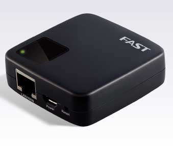
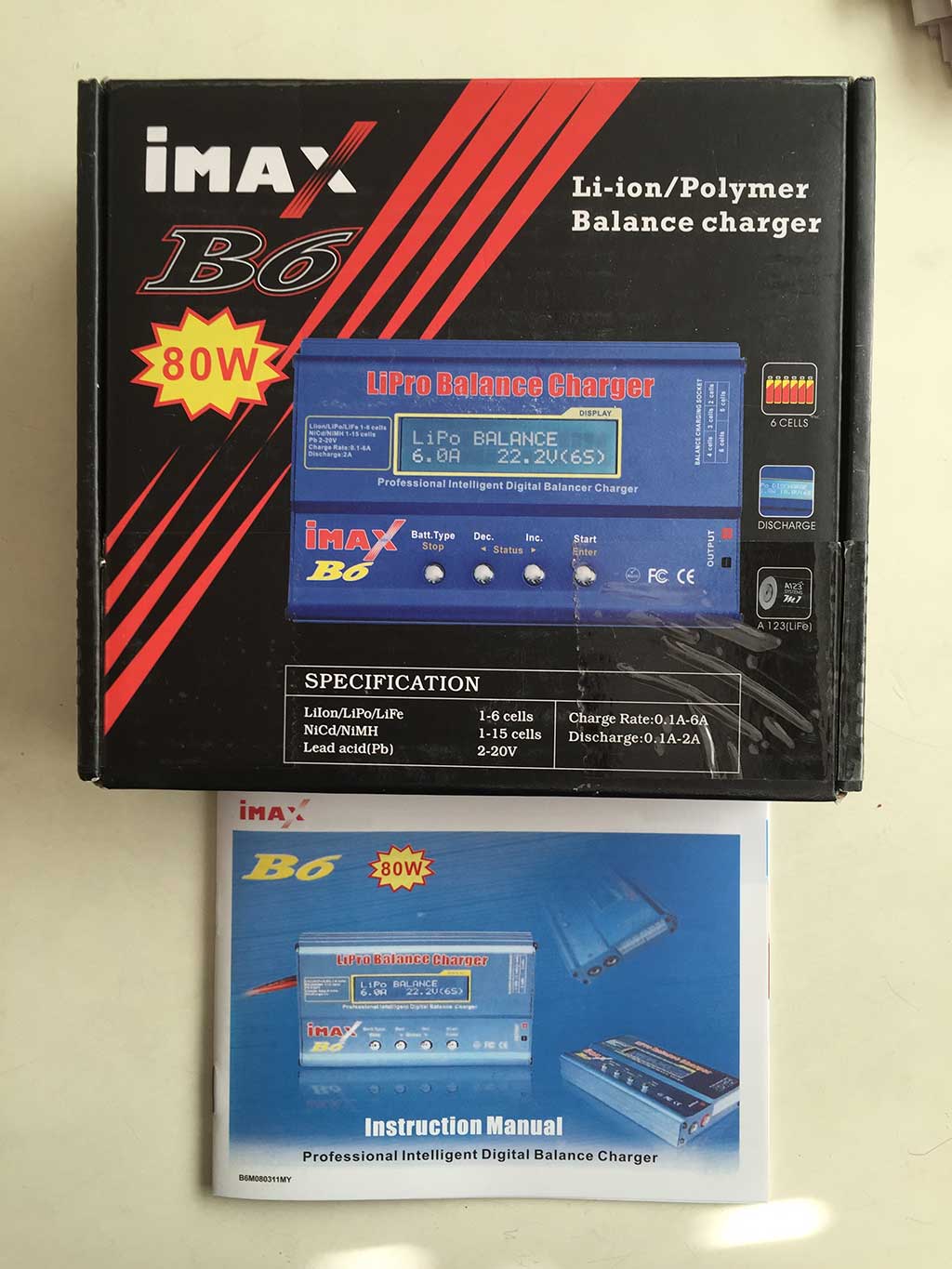
After reading about the SkyRC iMax B6 Charger on rcgroups, I decided to buy one. I chose a US-based seller, globalexcellent_ltd on eBay, and paid $17.99. The listing claimed that had a max charge power of 50W, and due to the low price, I figured I was getting a clone. I didn’t mind if it was a clone, because my plan was to install cheali-charger on it if it didn’t behave properly. I was surprised when a couple of days later, I received an 80W model:

imaxb6boxfront

I was also surprised (but skeptical) that there was a label on the back of the box claiming that it was a genuine SkyRC product:

imaxb6back

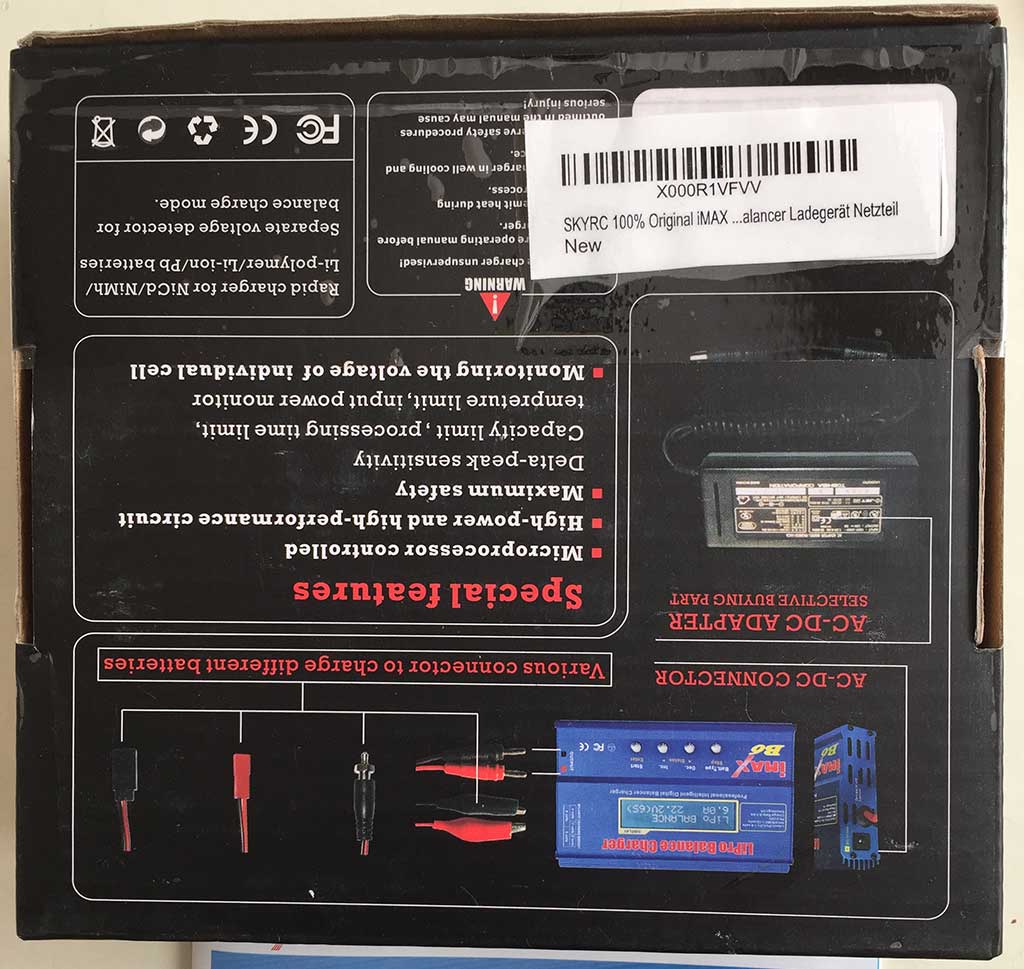
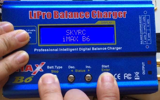
However, the box lacks the hologram which can be used to confirm a genuine product on SkyRC’s website, so I’m pretty sure it’s a fake. This is the start up message:

imaxb6startup

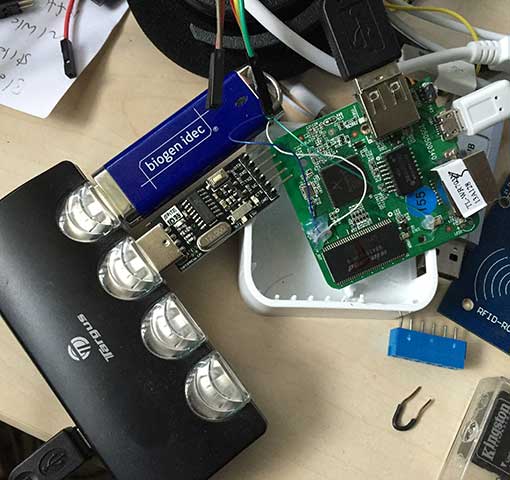
I did some initial testing, and found that it was almost half a volt off in its readings. My first thought was to try calibrating it via the Calibration Menu, which is supposed to be accessible by powering it up while simultaneously holding down the Dec and Start buttons. Much to my chagrin, I could not activate the calibration menu. Also, the Balancing Calibration Menu, which is supposed to be accessible by powering it up while holding down Stop and Inc didn’t work. After doing some searching, I found a discussion on the cheali-charger google discussion group about a Clone iMax B6 SKYRC (80W). It turns out the model in question has a mystery MCU which is not labeled, and is not compatible with cheali-charger. I took mine apart to see what PCB was inside:

imaxb6pcb

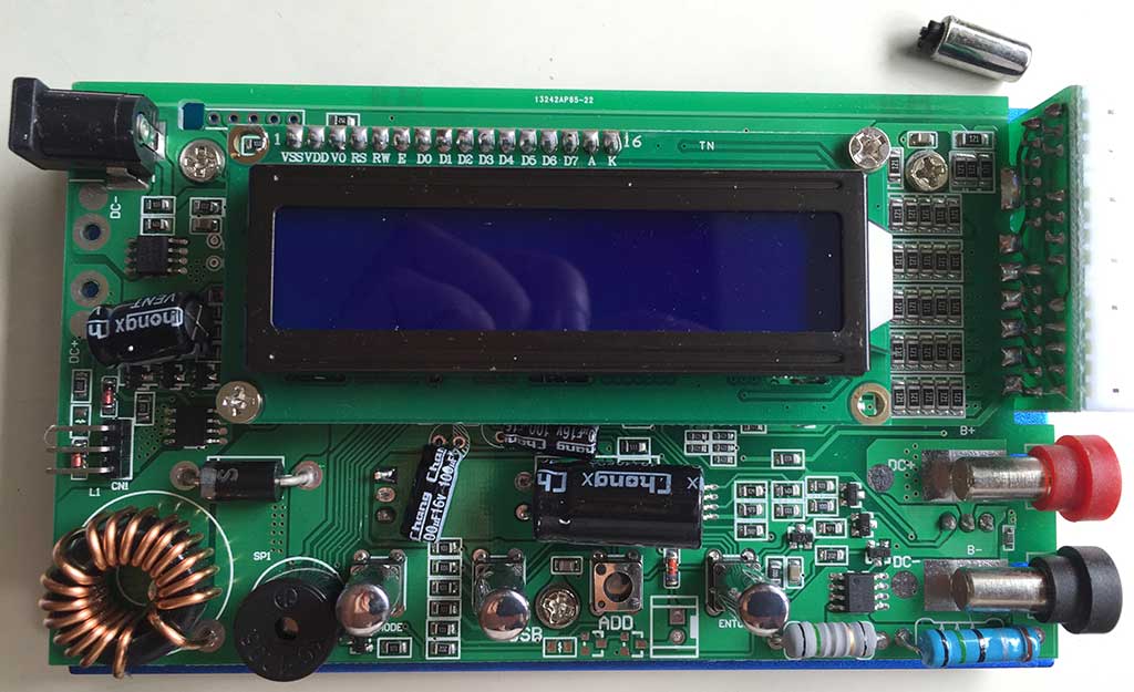
I forgot that the buttons were protruding from the case, so after I took off the end caps, I tried to slide out the PCB. Big mistake! I broke all 4 buttons! The proper way to remove the PCB is to carefully bend the case until the PCB can be pulled out the bottom of the case, rather than sliding it. Another diversion … I had to fix the broken buttons with super glue. After carefully examining the PCB, I figured out that I am unlucky, and mine is definitely the model with the unknown CPU that’s not compatible with cheali-charger. So, I had to find another way to make it functional.

CALIBRATION

It has come to my attention that there are versions with different firmware from mine. Apparently, some of them use a different calibration procedure. See Update 2017-02-01 below for the alternate calibration procedure. Currently, I don’t know how to tell which version you have.

From the google discussion thread, I found out that this particular version of the B6 has only one calibration menu, and it’s accessed by holding down the Stop and Start buttons while powering it up. It looks like the balance calibration menu on a normal B6 charger, showing 6 voltages. WARNING: DO NOT PRESS START AND STOP WHILE POWERING UP UNLESS YOU HAVE A CALIBRATION CIRCUIT HOOKED UP. OTHERWISE, IT WILL COMPLETELY MESS UP YOUR B6’s VOLTAGE CALIBRATION. Many people use a precision 25.2V power supply and 100 ohm .1% resistors to do the calibration (see Joe Rouvier’s post for this method), but having neither of those available, I decided to instead build up a 6S pack of fully charged LiPos. Here is the battery hookup:

b6balance

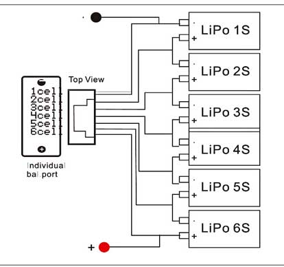
I charged each individual cell on another charger to exactly 4.19V. Also, according to Joe Rouvier’s post in the cheali-charger discussion, the temperature input also needs ~1V during calibration. The temperature port is located on the left side of the unit, and consists of a 3-pin header:

imaxb6temp

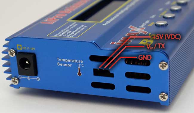
[above image copyright the owner of: http://sysmagazine.com/posts/150213/. Note, the TX function does not apply to fake 80W iMax B6’s. AFAIK, it is only for temperature input on this clone]

I hooked up a 5K potentiometer, outer terminals across the +5V and GND on the temperature port, center terminal (wiper) to Vin, and adjusted it to 1.00V between Vin and GND. I think if you don’t plan to hook up a temperature sensor, you can skip this step. The voltage calibration seemed to work OK without hooking anything up to the temperature port.

Once you have everything hooked up, power up the charger while holding down the Stop and Start buttons:

(Note, in the video, the temperature calibration circuit is not hooked up… I redid the calibration after I shot the video). After the voltages stabilize, calibration is complete, and the power may be disconnected. Interestingly, after the display stabilized, the iMAX B6 displayed all of the voltages exactly at 4.19V… spot on. This is different from I was expecting, because Joe Rouvier had mentioned that the charger just assumes every cell is 4.2V during calibration.

After calibration was complete, I tried test charging the battery that I used for calibration. I tried both Charge and Balance modes. In both modes, the main screen displayed the voltage as 25.1V, and after less than 1 minute, displayed FULL. But strangely, the cell voltage screen (press Inc during a charging session) was showing mismatched voltages (e.g. 4.20/3.94/4.18/3.98/4.19/4.12). In Balance mode, the voltages would start at the mismatched values, but then finally stabilize to be equal. However, after the charge session ended, if I started Balance mode again, the voltages would again be mismatched when the session started.

Next, I tried charging a single 3.7V/2000mAh LiPo cell. During charging, the 4.20V was always displayed, regardless of the actual voltage across the charge terminals. During the constant current phase, the voltage fluctuated, and often went above 5V. After ramping down the current charger stopped and displayed FULL and 4.20V. However, when I measured the cell with my DVM, it was 4.00V. I guess it’s good that it doesn’t overcharge and destroy your cells, but .2V low is a pretty big discrepancy. I tried restarting the session and playing with various charge currents from 2A-.2A, but it just kept stopping with the cell voltage exactly 4.00V.

Next, I hooked up my hand built 6S balancing pack again. Before charging, I verified that the cell voltages were still at 4.19V and triple checked the wiring. A normal Charge session ended with the both the battery and display at 25.1V, but the cell voltage screen was again displaying mismatched voltages. Next, I tried a Balance charge session again. This time, the charger started to smoke around the balance inputs! I quickly unplugged everything, but it was too late. The charger is now toast, as well as one of my one my LiPo cells, which now reads 0.00V.

Sheesh, what a short-lived charger. I don’t know if I just got a defective unit, or if this thing is junk, but I’m wondering whether I should try another iMax B6 or buy a different charger.

UPDATE 2015-07-28: Amazingly, the charger still works when not in Balance mode. At least, I’ve been charging single LiPo cells. It still charges them up to exactly 4.00V (though the display still always shows 4.20V during and after charging). This is what the board currently looks like:

imaxb6burned

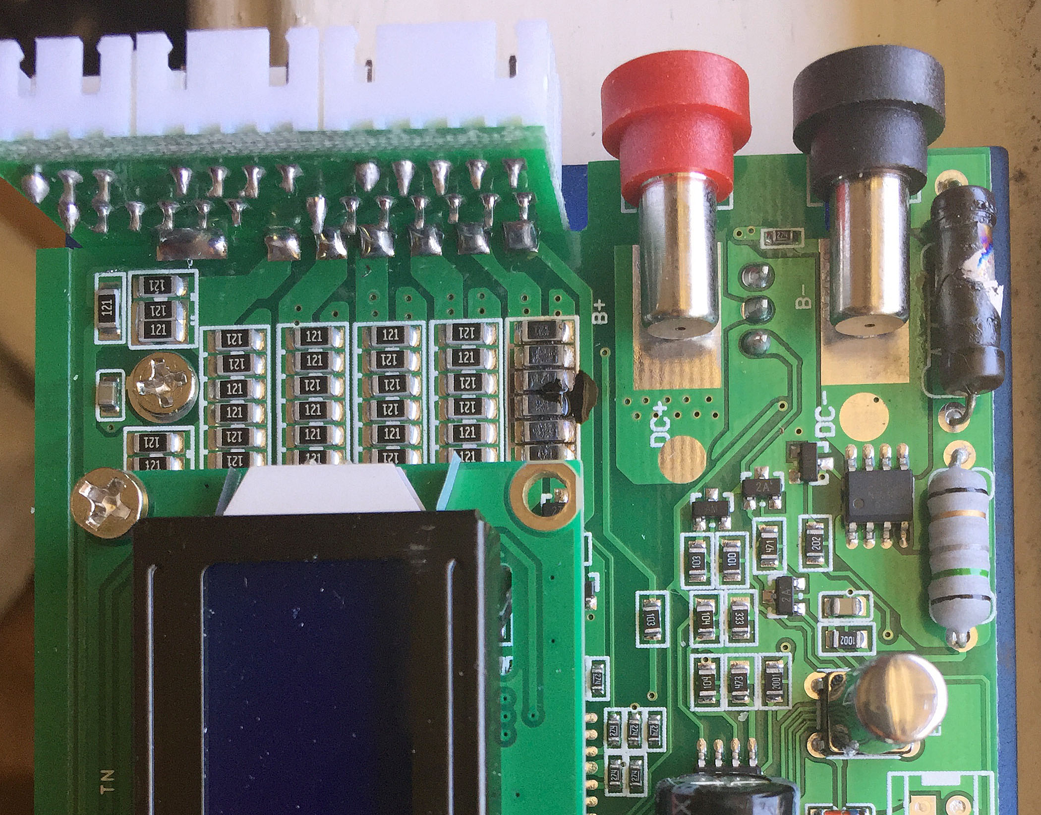
The rightmost row of balancer resistors is fried, as the power resistor at the top right. I’m not sure if I’m going to bother trying to fix it, since I can’t change the firmware to fix the 4.00V charge voltage bug.

Update 2015-08-04: OK, I’m a moron. I bought a genuine SkyRC 50W iMax B6 on Amazon, and it too seemed to be charging to exactly 4.00V as measured from the battery terminals. Then I found that during charging, the voltage at the charging terminals was 4.25V, while the voltage at the battery terminals was 4.00V. So, I tested the resistance of my charging jumpers, and found about 3 ohms resistance! The 4.00V terminal charging voltage was caused by excessive resistance in my charging jumpers! After swapping to some new jumpers, the genuine SkyRC iMax B6 charges 1S LiPo cells to 4.19V. Pretty good calibration from the factory. Next, I tried the fake 80W iMax B6 that I calibrated, and it too, charges to 4.19V. But there’s a big difference during charging. While adjusting current, the genuine iMax B6 never exceeds 4.25V while it’s adjusting the charging current. On the other hand, the fake 80W iMax B6 often overshoots in excess of 5V while adjusting down the charging current. I’m not sure if these temporary voltage spikes will damage your batteries or not, but to be on the safe side, I would avoid the 80W clone, until someone figures out how to get an open source firmware into it.

For those who want to keep up to date on developments with this charger, there is an ongoing discussion thread in the cheali-charger forum: Clone iMax B6 SKYRC (80W) . Perhaps someone will figure out how to program it.

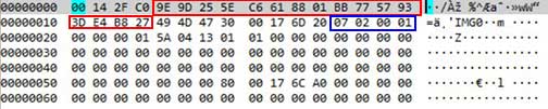
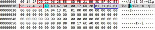
Update 2017-02-01: It seems that there are different versions of firmware on some of the newer models. Here is some info posted by MoPaZoDoZ92 on my YouTube video that may be helpful:

i had no calibration options on my fake Imax B6 2016 from ebay so i tried this video tutorial properly with 6s fully charged lipo batteries . The Imax displayed some random solid voltage (4.4v +- 0.2v) on each battery. Nothing else happened so i restarted the Imax. After that the imax automatically went to discharge lipo 1.0A S1 and of course gave me an “BATTERY CHECK HIGH VOLTAGE” error because all the 6S batteries was still connected with the balance cable and banana connectors. No buttons worked, though the Imax was broken. But i FOUND A SOLUTION on this particular Imax fake model.

Step 1: Follow Linco matics video tutorial properly with 6S fully charged batteries connected. Keep in mind that no buttons works under this process.

Step 2: Shutdown the Imax and connect only one S1 fully charged lipo battery with banana connectors.

Step3: Restart the Imax and it will automatically go to discharge lipo 1.0A S1 mode. It will discharge the battery for 10 SECONDS. After that the Imax will automatically cancel the discharge S1 mode and go to balance charge lipo 1.0A 6S mode. Here’s the tricky part, you have like 1 SECOND( until it display “BATTERY CHECK WAIT…”) to disconnect the S1 lipo Battery from the Imax and connect the fully charged S6 batteries you used for Lico Matics video tutorial with the balance cable and the banana connectors. If you fail this difficult task, the Imax will display an error and you need to shutdown the Imax and you’r back to step2.

You have to figure it out how to rapidly change the batteries. If you succeed the Imax will try to balance charge the S6 batteries in few seconds until the batteries are fully charged. After this process the calibration is completed and the buttons are enabled.

I have not yet found any solution on internet for this particular Imax fake model with no calibration option. So if you have the same symptoms i had with my fake Imax after following Lico Matics video tutorial you should try this out.

Sry for my bad english:)

Pyle PSWGP405BK GPS Watch Software and Firmware Updates

Today, I discovered that the New Balance NX990 GPS Cardio Trainer Watch, like the Pyle PSWGP405BK, is just another Latitude Limited Nav Master II clone.  Following my hunch, I searched for the NX990’s accompanying software, and lo and behold, it’s just rebranded version of GPS Master! Best of all, it’s an updated version, v2.0.16.124, vs the older v1.2 version that I got from Pyle. Besides the red background, it has a much improved interface, showing a google map of your track, and a zoomable graph with user selectable data that tracks your stats live on the map.

nbgpsmaster

So for instance, you can select the point on the graph where your heart rate is highest, and see where you were located on the map.

Best of all is the new Data Transfer->AGPS menu item. A-GPS (Assisted GPS) lets you use the Internet to download GPS satellite almanac data. Your GPS watch can download the almanac data directly via the satellites, but it is a very slow procedure. By connecting your watch to GPS Master once a week and downloading new AGPS data, you can get a hot GPS fix a lot faster. I wasn’t sure if my Pyle firmware had A-GPS support built in, so I took a risk, and used Setting->Watch firmware update to update my Pyle watch to the latest New Balance firmware. I’m happy so say that my watch did not get bricked! [DISCLAIMER: YMMV. I AM NOT RESPONSIBLE IF YOU DECIDE TO INSTALL THE NEW BALANCE FIRMWARE ON YOUR WATCH, AND IT TURNS INTO A PAPERWEIGHT] The New Balance v1.20 firmware appears to have all of the functions of my Pyle firmware. The most obvious difference is just that the screen fonts are more squared off looking. Some of the menus look slightly different, too. I took my watch outside after updating the AGPS data, and it got a GPS fix basically instantly!!

Another great discovery is that unlike my GPS Master 1.2, NB 990 GPS’s exported GPX track files now contain heart rate data! This means when upload your GPX track files to web sites such as RunKeeper, your heart rate data will be saved and displayed, as well. Meaning that you don’t have to use the csv2gpx/csv2tcx utilities that I wrote yesterday in order get your HRM data into other platforms.

All and all, I am very happy with both the software and firmware updates. I took my watch and HRM out for a workout today, and they worked flawlessly with the new firmware.

Downloads:

NX990 GPS Master PC Software
NX990 GPS Master User Manual
NX990 User Manual

Update 2015-03-15:

Here are some open source goodies for the watch:

Crane GPS Watch Client : command line utility. Most notably, it exports TCX files, which is important if you like to use the watch with the GPS turned off, since GPX files that contain HRM data w/o GPS data aren’t valid.

kalenji-gps-watch-reader : exports a multitude of formats, including Garmin FIT. Also performs elevation corrections via Google Elevation API.

GPX and TCX output from GPS Master Software

A couple of years ago, I bought a Pyle PSWGP405BK GPS watch with Heart Rate Monitor.

PSWGP405BK

It’s been a great device, though it’s big, and a bit ugly. The battery far outlasts my wife’s Garmin watches, and I love the customizable screens. My main problem has been the lack of a useful way to extract heart rate data. The problem is that the GPS Master software offers only two ways to export heart rate data: 1) TKL format, which is an undocumented file format used only by GPS Master, and 2) CSV format, which isn’t compatible with any web sites or software that I use.  Although GPS Master can directly export GPX files, they do not include the heart rate data.

I finally got sick of it today, and after wasting some time looking for an easy way to adapter existing converter software to work w/ GPS Master’s CSV files, I gave up, and decided to write my own programs. So, I give you csv2gpx, and csv2tcx. csv2gpx takes a GPS Master CSV file as input, and outputs a GPX file with heart rate data embedded. csv2tcx takes a GPS Master CSV file as input, and outputs a TCX file with heart rate data. Both programs have a simple command line interface. I have supplied full source code on github, so anyone can compile them to run on their own platforms. For Windows users, I have supplied EXE files. The command line syntax is quite simple:

csv2gpx workout.csv

or

csv2tcx workout.csv

The output will automatically be generated as workout.gpx and workout.tcx, respectively.

Here is a sample session:

C:\git\csv2gpx\test>csv2gpx 20150125074851.csv
Lincomatic GPS Master CSV to GPX Converter v0.2

Converting 20150125074851.csv -> 20150125074851.gpx
Avg HR: 131
Max HR: 159
Trackpoints 2398

Note that the output file is the same as the input file, but with GPX extension. csv2tcx works in a similar fashion.

I think csv2gpx and csv2tcx should work with any other watches that work with GPS Master, as well. Runtastic’s watch looks identical to my Pyle, as well as several other models that I’ve seen. For instance, the New Balance NX990 also uses GPS Master, and looks identical. As I’ve stated in a previous article, the watch is built by Latitude Limited, and the OEM calls it the Nav Master II.

Update 2015-01-27: Argh! I just confirmed that the fancy new updated version of GPS Master bundled with the New Balance NX990, aka NB 900 GPS, now exports HRM data inside its GPX files! So I wasted my time writing the utilities above yesterday! It has some nice UI enhancements, as well. Highly recommended! You can read my detailed description: Pyle PSWGP405GK Software and Firmware Updates.

Downloads: csv2tcx and csv2gpx executables for Windows

Installing English Firmware on a FAST FWR171

I recently learned that the FAST FWR171-3G is a lower cost clone of the TP-Link TL-WR703N, the only difference being the case. While browsing AliExpress, I found what I thought was a great deal… the FAST FWR171 for only $16. After waiting over a month to receive it, I noticed that it doesn’t have a USB port. Sheesh! I’m such an idiot. Just like when I mistakenly ordered a TL-WR702N from Amazon, it turns out that the FAST FWR171 is a clone of the TL-WR702N, not the TL-WR703N. AAARRGGGH!!! The trailing -3G in the FWR171-3G model number denotes the TL-WR703N clone!! So, not only did I end up with a router that’s useless for hacking, because it doesn’t have a enough RAM to load OpenWrt, has no USB port, and the firmware is in Chinese! FWR171_2 Notice the lack of a USB port in the photo of the FWR171 above. That alone should have warned me that I was ordering the wrong model. The FWR171-3G is slightly larger, and has a USB port on the side. Not wanting to be left with a completely useless device, I started browsing around for an English version of the firmware. None exists, but I found one for the TL-WR702N. Unfortunately, the web admin interface of the FWR171 checks the firmware for the correct device, and it won’t allow you to load a firmware for th TL-WR702N. Luckily, an OpenWrt forum member named jvvh5897 figured out how fool the firmware loader into thinking that it’s loading the appropriate firmware for a different model. In this thread, he describes how to modify an English TL-WR702N firmware to run on the Chinese model. I took that information, and used it to modify the English TL-WR702N firmware to run on the FW171. To adapt the TL-WR702N firmware to be accepted by the FWR171, we need to change two fields: 1) the system identifier and 2) the MD5 checksum of the firmware. In the TL-WR702N English firmware that I downloaded, the bytes in the blue box are the system identifier, and the bytes in the red boxes are the 16-byte MD5 checksum. 702fw Note that the system ID contains 0702 for the TL-WR702N. I downloaded a firmware for the FWR171 and found that the system ID was 01 71 02 01. To update the MD5 sum, you must calculate the MD5 sum of the entire file, with the dummy MD5 sum CC 96 28 EE 8D FB 21 BB 3D EF 6C B5 9F 77 4C 7C inserted. Here is what the file looked like after I prepared it for calculating the MD5 sum: 151fwdummy Next, I calculated the MD5 sum of the English TL-WR702N firmware file modified as above, and it was 06 7e a9 aa 7d 1e 75 10 b0 09 84 19 f1 d9 93 2d, so I replaced the dummy MD5 sum with those bytes and saved the file. Amazingly, the FW171’s firmware upgrader accepted it! To skip the hassle of modifying the firmware yourself, you can download my pre-hacked English TL-WR702N for FW171 firmware file. Using google, I found several descriptions of how to load the new firmware file into the FW171, but they were all wrong, because mine had the newer firmware, which checks for the proper system ID. To get to the web interface, set the IP number of your host computer’s Ethernet adapter to 192.168.1.3. Plug the FW171 into your host computer’s Ethernet port, and point a web browser to 192.168.1.253. Below is the firmware page for mine, which happened to be the latest firmware posted on www.fastcom.com.cn: fwver-sm To load your English firmware, you must set up a TFTP server on your host machine. In Windows, you can use TFTPD32. If you don’t know how to use TFTPD32, I have a description in this article. Point your TFTP server to the directory containing your firmware file, and type the name of the file into the box containing fwr171v1-cn-up.bin below: fwupg-sm   Click the bottom left button in the dialog, and a progress bar will appear, indicating that the firmware is being loaded. Once it is done, the device will automatically reboot, and your host computer should see a new WiFi AP with SSID TP-LINK_xxxxxx, where xxxxxx are the last 6 digits of your FW171’s MAC address. This indicates that you have successfully loaded your English TP-WR702N firmware! Next, set your host computer’s Ethernet port to DHCP, and plug the FW171 into it. Your host computer will receive an IP number in the range of 192.168.0.X. Point your web browser to the TL-WR702N’s IP number 192.168.0.254, and log in with user admin, password admin.

Downloads: English TL-WR702N firmware for FW171

How to Repair a Panasonic Massage Chair, Part 3

Unfortunately, my rubber hose hack from Part 2 worked only for a few weeks. The belt again stretched, and became loose:

loosebelt

One thing you can also see in the photo above is that I’ve slid the motor as far to the left as the adjusters allow (the slotted holes for the two brass screws). I couldn’t bend the motor mounts any more to tighten up the belt, so in addition to the rubber hose shim from Part 2, I wrapped 4 layers of electrical tape around each of the two pulleys:

tapedpulley

Amazingly, this increased the diameter of the pulleys enough that the belt became taut. I have tested the chair for a few hours, and this fix seems to be working well. Let’s see how long this hack holds up…

Previous related article: How to Repair a Panasonic Massage Chair, Part 2

Quickie Hack: Turn Your Bicycle Into A Party Machine

I was looking for a way to play tunes while biking the other day, and was too lazy to get out the CAD program and design something to print on my RepRap. Here’s a dirt cheap & quick hack to get some decent quality sound while riding your bike. All you need is 4 zip ties:

party1

party2

party3

party4


The only tricky part is that I criss-crossed the ties that attach it to the bike.. that is, I took the end of one tie and inserted it into the other tie, instead of its own end. This added some stability, and prevents the speaker from getting damaged due to rubbing against the handlebars. Be sure to rotate the speaker to the proper orientation for you to access its controls before tightening it up.

The speaker I used is a cheap Chinese fake Beats by Dr Dre speaker. I bought it on AliExpres for $13.88 including shipping from China. It’s also known as the “S11 bluetooth speaker,” and is available on eBay, as well. It has a built-in lithium-ion battery, Bluetooth connectivity, including speakerphone (the microphone is crap, though), and even has pause and track skipping buttons. It also has a cable for connecting it via a headphone jack, and even sports a microSD slot, so you can use it completely standalone. Not only is it loud, but the sound is actually better than lots of speakers I’ve tried that cost a lot more. The black model has a rubberized casing, which helps avoid damage from rough handling. It also comes in a rainbow of colors, some with metal casing, instead.

Now, I just keep my iPhone in my pocket, and pause/skip tracks using the buttons on the speaker. The speaker doesn’t have a volume control, but I can easily reach in my pocket and hit the volume buttons w/o looking at it. I took it on a 50 mile bike ride the other day, and the speaker didn’t vibrate off.


OpenWrt: Cross-compiling libmicrohttpd for TL-WR703N

Recently, I’ve been developing embedded webapps using node.js. Unfortunately, node.js is a bit bloated for resource-constrained platforms, such as the TL-WR703N running OpenWrt. Not only is it too large to fit into flash memory, requiring an external USB drive to run EXTROOT, but I’ve even encountered circumstances where I’ve been running out of RAM. Thus, I’ve been looking for a lean & mean HTTP library written in C. Right now, my top two candidates are axTLS and libmicrohttpd. Since it’s impractical to host a toolchain on the TL-WR703N, we have to cross-compile everything, which can be a bit of a chore to set up. The first step is to download and unpack the source code:

% wget http://ftp.gnu.org/gnu/libmicrohttpd/libmicrohttpd-0.9.38.tar.gz
% tar xzvf libmicrohttpd-0.9.38.tar.gz

If you don’t already have an OpenWrt toolchain set up, you can download and install it as follows:

% wget http://downloads.openwrt.org/attitude_adjustment/12.09/ar71xx/generic/OpenWrt-Toolchain-ar71xx-for-mips_r2-gcc-4.6-linaro_uClibc-0.9.33.2.tar.bz2
% bzip2 -dc OpenWrt-Toolchain-ar71xx-for-mips_r2-gcc-4.6-linaro_uClibc-0.9.33.2.tar.bz2 | tar xvf –

Next, we need a build script. Save the bash script below as build_libmicrohttpd_mipsbe.sh:

[code language=”bash”]
#!/bin/bash
#
# compile libmicrohttpd for ar71xx (mipsbe)
#

export BASEDIR=$(pwd)

### begin configuration

# node src directory
export SRCDIR=libmicrohttpd-0.9.38

#adjust STAGING_DIR and TOOLDIR below based on location of your toolchain
#ToolChain
export STAGING_DIR=${BASEDIR}/OpenWrt-Toolchain-ar71xx-for-mips_r2-gcc-4.6-linaro_uClibc-0.9.33.2/toolchain-mips_r2_gcc-4.6-linaro_uClibc-0.9.33.2
#export STAGING_DIR=${BASEDIR}/openwrt/attitude_adjustment/staging_dir

export TOOLDIR=${STAGING_DIR}/toolchain-mips_r2_gcc-4.6-linaro_uClibc-0.9.33.2

### end configuration

export TARGET_PATH=${BASEDIR}/${SRCDIR}-mipsbe
export PREFIX=${TOOLDIR}/bin/mips-openwrt-linux-
export LIBPATH=${TOOLDIR}/lib/

# MIPS cross-compile exports
export CC=${PREFIX}gcc
export CXX=${PREFIX}g++
export AR=${PREFIX}ar
export RANLIB=${PREFIX}ranlib
export LINK=${PREFIX}g++
export CPP="${PREFIX}gcc -E"
export STRIP=${PREFIX}strip
export OBJCOPY=${PREFIX}objcopy
export LD=${PREFIX}g++
export OBJDUMP=${PREFIX}objdump
export NM=${PREFIX}nm
export AS=${PREFIX}as
export PS1="[${PREFIX}] \w$ "
export LDFLAGS=’-Wl,-rpath-link ‘${LIBPATH}

rm -rf ${TARGET_PATH}
mkdir ${TARGET_PATH}
cd ${SRCDIR}
make clean
make distclean
./configure –prefix=${TARGET_PATH} –host=mips-openwrt-linux-uclibc –without-snapshot –with-mips-float-abi=soft
make
make install
[/code]

If your toolchain is in a different place from the STAGING_DIR specified in the script, adjust it to point to the proper location. Finally, execute the build script:

% sh build_libmicrohttpd_mipsbe.sh

After the build is complete, you can test it out by transferring one of the example files to your TL-WR703N running OpenWrt. A good candidate would be src/examples/fileserver_example. In addition to the executable, you also need to get the shared library onto your OpenWrt machine. It is built into a strange location: src/examples/microhttpd/.libs/libmicrohttpd.so.10. Put the file in /usr/lib/libmicrohttpd.so.10 on your target machine. Finally, you should be able to execute fileserver_example on the target machine.

TL-WR703N: Attaching USB Serial Adapters – FTDI/CP2102/PL2303/CH340G

Although the TL-WR703N has a built in UART, as I have shown in my previous article, it’s rather difficult to access, and is useful as a serial console in OpenWrt. For the support of your own apps, it is far more convenient to simply plug in a cheap USB to serial adapter — this can be done without even opening the case. Since the TL-WR703N only has one USB port, if you are using EXTROOT, both the serial adapter and the USB flash drive can be attached to a USB hub: usbserialThe TL-WR703N can easily supply the required current, so an unpowered hub may be used. To add support for USB to serial hardware, use opkg to install the appropriate modules. Basic USB to serial support:

opkg install kmod-usb-serial

FTDI (FT232) support:

opkg install kmod-usb-serial-ftdi

Silicon Laboratories CP210x (CP2102) support:

opkg install kmod-usb-serial-cp210x

Nanjin QinHeng Electronics CH341 (CH340G):

opkg install kmod-usb-serial-ch341

Prolific PL2303 support:

opkg install kmod-usb-serial-pl2303

Additionally, OpenWrt has packages for a slew of other USB serial adapters that I’m not familiar with. If you are using Attitude Adjustment (12.09) and its official repository, here are the other supported adapters:

kmod-usb-serial-ark3116 kmod-usb-serial-belkin -- Belkin
kmod-usb-serial-cypress-m8
kmod-usb-serial-ipw
kmod-usb-serial-keyspan
kmod-usb-serial-mct -- Magic Control Technology
kmod-usb-serial-mos7720
kmod-usb-serial-motorola-phone
kmod-usb-serial-oti6858
kmod-usb-serial-qualcomm
kmod-usb-serial-sierrawireless
kmod-usb-serial-ti-usb
kmod-usb-serial-visor -- Handspring Visor/Palm m50x/Sony Clie

After you install the appropriate kernel modules, your USB to serial converter will show up as /dev/ttyUSBx

[ 489.990000] usb 1-1.3: new full-speed USB device number 5 using ehci-platform
[ 490.100000] ch341 1-1.3:1.0: ch341-uart converter detected
[ 490.120000] usb 1-1.3: ch341-uart converter now attached to ttyUSB0


How to Repair a Panasonic Massage Chair, Part 2

In my article, How to Repair a Panasonic Massage Chair, I described how I fixed my Panasonic EP1004 massage chair. The chair worked for a year or so, and then stopped working again. The symptoms this time were a bit different from when the clutches got stuck. Instead of running for a while, and then beeping and shutting itself off, the massage mechanism stopped moving up and down. The chair was just stuck in kneading mode, and wouldn’t do anything else. +I was pretty sure the problem was due to a loose belt, but just didn’t feel like taking it apart again. Tonight, I decided it was time to get it working again. I opened it up, and sure enough, one of the belts had slackened so much that the pulleys were just freewheeling. The loose belt was the small one on the far left in the photo below:

belt


The belt doesn’t look loose in the photo, because I forgot to take a photo of it before tightening it up. Unfortunately, there was no adjustment left to tighten the belt. It must have stretched over it’s 15+ year lifetime. I’m pretty impressed by the quality of the of the belts in this thing. They haven’t dried up at all. If you look in the photo below, there are two screws in horizontal slots between the two pulleys. Note that the screws are all the way on the left of the slots, which means that the motor has already been slid as far as it will go to the right. Yet, the belt was still quite loose. I finally jerry rigged a fix by jamming a piece of rubber hose in between the motor and the metal box it’s attached to. To stiffen up the hose, I stuffed a wood dowel into it. The rubber hose is in the photo below, under the green/yellow wire that grounds the motor to the chassis.

beltfix

The chair is now working again… until something else goes wrong.

Previous related article: How to Repair a Panasonic Massage Chair
Next related article: How to Repair a Panasonic Massage Chair, Part 3


gCode Visualization

I was working on a project today, which had some serious overhangs. I added support material manually, but needed to make sure that slic3r was traversing a usable path through my supports. Usually, I use Repetier Host‘s excellent built-in gCode visualizer, but it only displays a layer at a time, and I needed to see the actual paths followed in each layer. After searching a bit, I found an excellent online visualizer: gcode.ws:

Image3


It is very full featured, with sliders that let you step through your gCode layer by layer, and also line by line within a layer. Additionally, it prints out a lot of useful statistics within your gCode.

While running it in a web browser is handy, since you don’t need to install any software, sometimes, I need to have access to it when I have no Internet access. Fortunately, the visualizer is open source, and is written in javascript, so you can also run it directly from your hard drive. First, download the zip archive from github:

https://github.com/hudbrog/gCodeViewer/archive/master.zip

Unzip the archive, and simply launch index.html. I had security issues running it in Chrome, and it froze up in Internet Explorer, but Firefox runs it just fine. To run it in Chrome, you must launch it with the command line option “–allow-file-access-from-files” in order to lower the security so that it can access files locally, but it doesn’t work if you already have a running copy of Chrome.

On Windows computers, if Firefox isn’t your default browser, you can just right-click index.html, and select Open with->Firefox.

Image3


Many thanks to hudbrog for making this excellent tool.