AVR CAN Bus Project – Step 3: CANspy CAN Bus Monitor

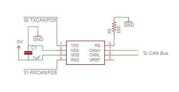
Sorry for the delay in posting the circuit and schematics from my AVR CAN Bus Project – Status Update 1.  The circuit for interfacing the Olimex AT90CAN128 Header Board is incredibly simple, and only requires 3 components.

Parts List
(1) .1uF ceramic capacitor
(1) 10K resistor
(1) Microchip MCP2551 CAN transceiver

Schematic

If you’re going to connect it to a Nissan Leaf, the car has 3 different CAN buses accessible via the OBD-II connector. The pinouts can be found on MyNissanLeaf.com in this thread: Leaf CANbus Decoding (Open Discussion)

To communicate with the AT90CAN128 header board from my PC, I connected a USB to serial converter to USART0: TXD0 (pin 3) and RXD0 (pin 2).

Arduino Sketch

Below is my CANSpy sketch for monitoring the CAN bus via the serial port, as depicted in my Status Update 1.

Download: CANspy.zip

To compile the sketch, follow the instructions in AVR CAN Bus Project – Step 1: Programming AT90CAN128 with Arduino.

In my next update, I’ll show how to implement a SOC (State of Charge) meter for the Leaf using a LCD display.
Previous: AVR CAN Bus Project – Status Update 1
Next: AVR CAN Bus Project: Step 4 – Nissan Leaf SOC Meter

AVR CAN Bus Project – Status Update 1

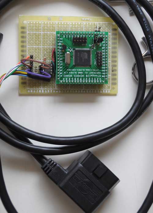
I got the circuit wired up yesterday:

The 6-pin jumper on the left lets me select one of the 3 CAN buses on the Nissan Leaf accessible via the OBD-II connector.

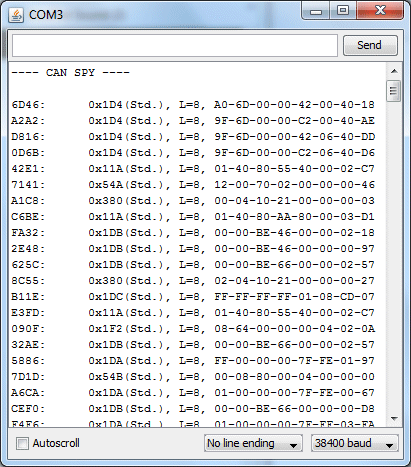
I hacked up some code quickly, and was pleasantly surprised that it actually worked! Woohoo! The part I thought was going to be most difficult – getting the CAN interface firmware working – turned out to be the easiest. Here’s my first capture of live data from the EV CAN bus:

Schematic and source code will follow.

Previous: AVR CAN Bus Project – Step 2: Programming Low Fuse
Next: AVR CAN Bus Project – Step 3: CANSpy CAN Bus Monitor

AVR CAN Bus Project – Step 2: Programming Low Fuse

One of the basic functions that the CAN Bus project needs is to be able to communicate with a PC via a serial port.  For modern PC’s the most straightforward way is to connect the AT90CAN128 header board to the host via a Serial->USB converter.  The most common type is the ubiquitous FTDI Cable, which is a USB cable with an embedded FT232R chip inside. Since I have a couple of spare Arduinos, I like to just use the embedded FT232R in the Arduino, rather than investing in a FTDI cable.  To use an Arduino as a serial cable, simply remove the ATmega328P MCU, and then connect the the TxD, RxD, and GND pins between the Arduino and the external device.

The AT90CAN128 has two USART’s.  The first one, on pins RXD0(2) and TXD0(3), is accessed via the Serial object in Arduino.  The second one, on pins RXD1(27) and TXD1(28), is accessed via the Serial1 object in Arduino.

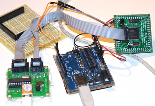
To test serial communications with the host PC, I connected the first USART to the Arduino board with MCU removed as follows:

AT90CAN128 RXD0 pin 2 -> Arduino Digital 0 (RX)
AT90CAN128 TXD0 pin 3 -> Arduino Digital 1 (TX)
AT90CAN128 GND pin 53 -> Arduino GND
Then I wrote a quick sketch to simply read characters from USART0 and echo them back to the PC:

void setup()
{
Serial.begin(38400);
}

void loop()
{
while (Serial.available()) {
int c = Serial.read();
Serial.write(c);
}

To instead test the 2nd USART, substitute RXD1 for RXD0, TXD1 for TXD0, and Serial1 for Serial.

After burning the sketch, I simply opened the Arduino Serial Monitor, and typed characters to test the connection.  Much to my chagrin, the AT90CAN128 was echoing garbage back to the host.  I spent hours trying various things, checking and rechecking my wiring, to no avail.  I started to suspect that maybe the at90can files I got from SuperCow were inproperly configured.  One thing that raised this suspicion is that I found that the delay() function was running much slower than it should.  User evnow of the MyNissanLeaf forum pointed me to a HEX file of a similar serial echo program that Olimex posted on their site for the AVR-CAN board.  I burned the file into the AT90CAN128 using avrdude:

avrdude -c usbtiny -p at90can128 -U flash:w:avr-can_UART.hex

Once again, the board was corrupting the serial data.  This test showed that the culprit probably wasn’t SuperCow’s at90can files, since this hex file has been tested and working by other users.

Finally, it dawned on me that perhaps the fuses weren’t properly programmed.  I got a crash course on fuses from Adafruit’s avrdude tutorial.  Adfruit’s tutorial also linked to a great AVR fuse calculator.  First, I read out the fuses to 3 files:

avrdude -c usbtiny -p at90can128 -U lfuse:r:lfuse:h
avrdude -c usbtiny -p at90can128 -U hfuse:r:hfuse:h
avrdude -c usbtiny -p at90can128 -U efuse:r:efuse:h

The 3 commands above read the low, high, and extended fuses respectively, and output them as text files lfuse, hfuse, and efuse.  I found that the values were lfuse=0x4f, hfuse=0x19, efuse=0xff.  Using the Embedded Atmel AVR Fuse Calculator, I noticed that when lfuse=0x4f, that CKDIV8 (Clock divide by 8)  is enabled.  This didn’t seem right, and might account for the fact that the delay() function seemed to be running about 8x too slow.  Not knowing much about fuses, I decided to just use the value that Arduino uses for the ATmega328P, lfuse=0xFF, which turns off CKDIV8.

avrdude -c usbtiny -p at90can128 -U lfuse:w:0xFF:m

Bingo!  No more corrupted serial data, and the delay() function now runs at normal speed.  I have a feeling I’ll have to play with the other fuse bits at a later date, but since the board is working OK I’ll leave them be for now.  If you want to copy all of my current fuse settings, use this command:

avrdude -c usbtiny -p at90can128 -U lfuse:w:0xFF:m -Uhfuse:w:0x1F:m -U efuse:w:0xFF:m

Previous:  AVR CAN Bus Project – Step 1: Programming AT90CAN128 with Arduino
Next: AVR CAN Bus Project – Status Update 1
AVR CAN Bus Project – Step 1: Programming AT90CAN128 with Arduino

Last month, I bought a Nissan Leaf EV.  It’s pretty cool driving around in an all-electric car.  Luckily, there’s a great forum called MyNissanLeaf, where Leaf owners can learn a lot, and share information.  I’m currently collaborating with one of the forum members to design and build a Level 2 EVSE.  I will document that project on this blog at a later date.  Having a serious case of project ADHD, I discovered that forum members had set about hacking the Leaf’s CAN buses, and couldn’t resist joining the fray.

Being most familiar with ATmel AVR microcontrollers and Arduino, I decided to use that platform for this project.  ATmel has a subtype of the AVR with CAN bus capabilities, the AT90CANxxx.  I found an interesting development board containing an AT90CAN128 and headers for access to all the pins on the MCU.  I ordered one from Sparkfun for $29.95.  They also sell another board, the AVR-CAN, but it contains things that I don’t need, such as an RS-232 interface, and can be programmed only via JTAG – I only have a USBtinyISP, which is an ICSP programmer.  Unlike the AVR-CAN, the AT90CAN128 Header Board doesn’t contain a CAN Bus transceiver.  I decided to go with the Microchip MCP2551, since that’s what the AVR-CAN uses.

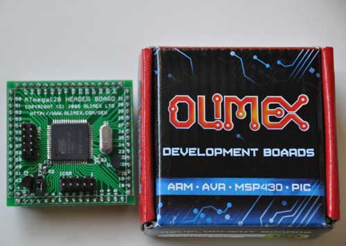
The AT90CAN128 header board is from Olimex, and comes in a cute little box:

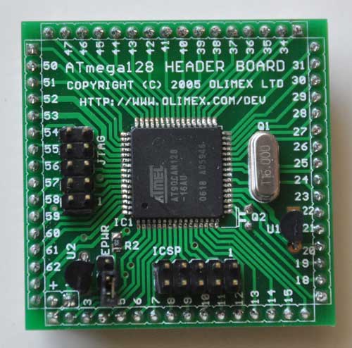
Here’s a closeup of the front:

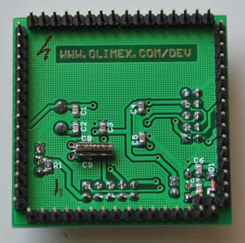
and the back:

I decided to try to get this board working with Arduino, since it’s a lot easier to set up than WinAVR.  The first problem to solve is how to adapt the Arduino IDE to work with the AT90CAN128 and my USBtinyISP.  After much Googling, I found SuperCow had already done the dirty work and posted it to the Arduino forum.  He packaged the core files, bootloader, and a couple of examples into a handy zip file (which has since been taken offline). Since he used an unknown JTAG programmer, I had to adapt his files to work with the USBtinyISP and JTAG ICE mk1.  Also, I modified them to work with Arduino 1.x+.

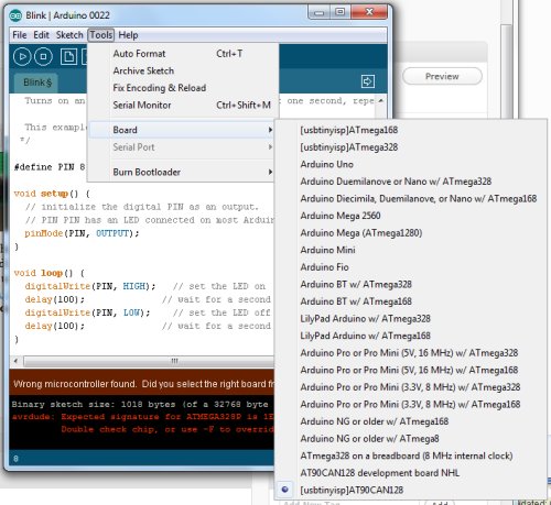
You can download the latest version from github: https://github.com/lincomatic/AT90CAN  To install it, simply unzip the atcan90 directory into <your arduino directory>/hardware/at90can.  Next time you restart Arduino, you can select it from Tools->Board->[usbtinyisp]AT90CAN128.

If you have a JTAG ICE mk1 programmer instead, select [JTAG ICE mk1]AT90CAN128.

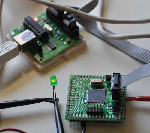
I connected up my USBtinyISP via the 10-pin ICSP header, burned the Blink sketch, hooked up an LED, and bingo!  It’s working flawlessly.

In at90can/cores/at90can, I found can_lib.h and can_lib.cpp, which appear to be all we need to interface to the CAN bus.  Since I currently know ZERO about CAN bus, I have a lot of reading to do before I can commence programming.  SuperCow’s original zip file contains a couple of rudimentary examples.

Before I start programming, I need to build a little interface board containing the MCP2551 CAN bus transceiver, which should arrive next week.  I already have an OBD-II cable to tap into the Leaf CAN bus via the OBD-II connector.  Currently, obdcables.com is having a special on the 9-ft model.


Downloads:  https://github.com/lincomatic/AT90CAN

Next: AVR CAN Bus Project – Step 2: Programming Low Fuse