TL-WR703N: Attaching USB Serial Adapters – FTDI/CP2102/PL2303/CH340G

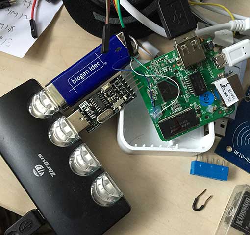
Although the TL-WR703N has a built in UART, as I have shown in my previous article, it’s rather difficult to access, and is useful as a serial console in OpenWrt. For the support of your own apps, it is far more convenient to simply plug in a cheap USB to serial adapter — this can be done without even opening the case. Since the TL-WR703N only has one USB port, if you are using EXTROOT, both the serial adapter and the USB flash drive can be attached to a USB hub: usbserialThe TL-WR703N can easily supply the required current, so an unpowered hub may be used. To add support for USB to serial hardware, use opkg to install the appropriate modules. Basic USB to serial support:

opkg install kmod-usb-serial

FTDI (FT232) support:

opkg install kmod-usb-serial-ftdi

Silicon Laboratories CP210x (CP2102) support:

opkg install kmod-usb-serial-cp210x

Nanjin QinHeng Electronics CH341 (CH340G):

opkg install kmod-usb-serial-ch341

Prolific PL2303 support:

opkg install kmod-usb-serial-pl2303

Additionally, OpenWrt has packages for a slew of other USB serial adapters that I’m not familiar with. If you are using Attitude Adjustment (12.09) and its official repository, here are the other supported adapters:

kmod-usb-serial-ark3116 kmod-usb-serial-belkin -- Belkin
kmod-usb-serial-cypress-m8
kmod-usb-serial-ipw
kmod-usb-serial-keyspan
kmod-usb-serial-mct -- Magic Control Technology
kmod-usb-serial-mos7720
kmod-usb-serial-motorola-phone
kmod-usb-serial-oti6858
kmod-usb-serial-qualcomm
kmod-usb-serial-sierrawireless
kmod-usb-serial-ti-usb
kmod-usb-serial-visor -- Handspring Visor/Palm m50x/Sony Clie

After you install the appropriate kernel modules, your USB to serial converter will show up as /dev/ttyUSBx

[ 489.990000] usb 1-1.3: new full-speed USB device number 5 using ehci-platform
[ 490.100000] ch341 1-1.3:1.0: ch341-uart converter detected
[ 490.120000] usb 1-1.3: ch341-uart converter now attached to ttyUSB0


RepRap: Printrboard Surgery

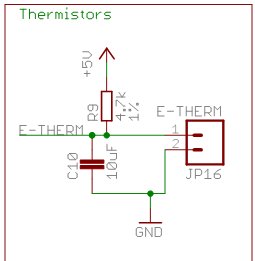
After a hiatus of a couple of years, I’m finally starting to get back into 3D printing. One of my Printrboards got messed up when some wires on my hot end shorted. The hot end temperature was no longer reading correctly. Since my other Printrboards all work correctly, I knew that the problem was not a bad thermistor or wiring. Instead of throwing out the Printrboard, I decided to try to fix it. The first step was to have a look @ the Printrboard schematic. Here’s what the temperature sensing circuit looks like:

tempckt


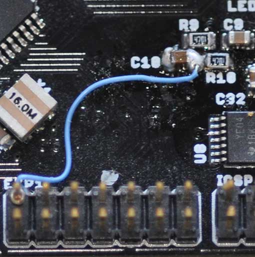
I got out my ohmmeter, and R9 was OK, but E-THERM to GND was reading as a dead short, so I assumed that C10 was bad. This was a good opportunity to play with my AOYUE INT 2702 hot air rework station, which I’d never used. I removed C10, and much to my chagrin, the reading from the hot end ADC pin was stuck at 1024. Furthermore, shorting E-THERM to ground was causing my Printrboard to reboot! This led me to conclude that something was fried inside the AT90USB1286 on the ADC pin connected to E-THERM (PF1_ADC1). Conveniently, 2 other ADC pins, ADC2 and ADC3, are broken out into an expansion header on the Printrboard. I first soldered C10 back into place. The trace connecting ADC1 to E-THERM was inaccessible, so I couldn’t cut it. Instead, I disconnected it by lifting the pin on the MCU off the PCB. Next, I connected a piece of 40AWG wire wrap wire between the A2 header pin and the E-THERM trace.

pbfix

Success, the ADC2 pin is working perfectly! The only caveat is that I have to remember to run modified firmware when using this board, reassigning the hot end thermistor pin from ADC1 to ADC2. In Marlin firmware, it’s as simple as finding the Printrboard section of pins.h, and reassigning TEMP_0_PIN from 1 to 2.

Arduino 1.0.5-r2 for AT90USB1286 and Printrboard

It’s been a few years since I hacked together the copy of Arduino-0022 that’s been floating around the web, which lets you compile and automatically upload Arduino code to an AT90USB1286. This made it a lot easier to develop Arduino code for the AT90USB1286, and in particular to easily modify the Marlin firmware for the Printrboard.

Yesterday, I figured it was high time to add AT90USB1286 support to Arduino 1.0.5-r2. The basic procedure for the modification was to first install Teensyduino, which adds the AT90USB1286 compilation support to Arduino, but only uploads to a Teensy++ 2.0, running PJRC’s proprietary halfkay bootloader. I modified the Teensyduino configuration to also support uploads to targets running the LUFA CDC Bootloader, or via USBtinyISP or USBasp ICSP programmers.

Note that I copy that I modified only runs on Microsoft Windows.
You can download it from github: https://github.com/lincomatic/arduino-1.0.5-r2-at90usb1286
It’s easiest to download it as a zip file: https://github.com/lincomatic/arduino-1.0.5-r2-at90usb1286/archive/master.zip

Once you unzip the archive and launch arduino.exe, you will notice some new entries in the Tools->Board menu:

[USBasp]AT90USB1286
[usbtinyisp]AT90USB1286
[BootloaderCDC]AT90USB1286
[USBasp]Printrboard
[usbtinyisp]Printrboard
[BootloaderCDC]Printrboard

The only difference between the Printrboard and AT90USB1286 entries is that the extraneous USB Type, CPU Speed, and Keyboard Layout submenus are grayed out from the Tools menu.

To load Marlin firmware onto a Printrboard, you will most likely want to use [BootloaderCDC]Printrboard.

Note that unlike my Arduino-0022 hack, the pinMode()/digitalRead()/digitalWrite() functions in version currently only support the pins that are exposed on the Teensy++ 2.0. This is because I haven’t yet had the time to figure out how to add in the remaining AT90USB1286. However, this limitation doesn’t affect Marlin firmware on the Printrboard, because Marlin uses its own fastio functions, rather than using Arduino digital pin numbers and pinMode()/digitalRead()/digitalWrite(). See pinmap.txt for the currently supported Arduino digital pin numbers.

Thanks again to PJRC for Teensyduino. Teensys are a great alternative to Arduino boards.

How to Update the Firmware on a USBasp V2.0

REVISED 2018-07-16

If you buy a cheap USBasp V2.0 ICSP programmer on eBay, chances are, avrdude will give you the following warning message:

avrdude: warning: cannot set sck period. please check for usbasp firmware update.

While it’s just a benign warning message which can be ignored with no ill effects, it’s still a constant irritant. Furthermore, it also prevents my speed up technique from working, because it relies on changing the sck period. To get rid of the warning, you must update the firmware to the latest version: usbasp.2011-05-28.tar.gz

If you have another ICSP programmer already, such as a USBtinyISP, programming in the new firmware is quite simple. If you have more than one USBasp, you can even use them to program each other. Here are the steps:

0. Verify that you have a USBasp V2.0, and that it has a 12MHz crystal and an ATMEGA8 or ATMEGA8A MCU onboard. DO NOT CONNECT IT TO THE USB PORT OF YOUR COMPUTER.

1. Short the JP2 (self-programming) jumper.

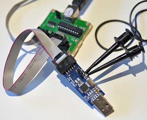
2. Connect the USBasp V2.0 to the USBtinyISP (or other ISP) using a 10-pin ribbon cable

usbasp

3. Flash in the new firmware: avrdude -c usbtiny -p atmega8 -U flash:w:usbasp.atmega8.2011-05-28.hex

4. Reprogram the USBasp’s fuses: avrdude -c usbtiny -p atmega8 -u -U hfuse:w:0xc9:m -U lfuse:w:0xef:m

If you’re not using a USBtinyISP, substitute the proper parameter after -c (e.g. -c usbasp).

Note that the usbasp.2011-05-28.tar.gz archive doesn’t contain a compiled .hex file, so you have to re-compile it using WinAVR. Instead, you can just use my hex file, which I compiled directly from the sources: usbasp.atmega8.2011-05-28.zip

If you don’t have another ICSP programmer, you can use an Arduino, following these instructions: Updating firmware on USBASP bought from eBay. However, you may also have to also set the fuses according to Step 3 above. My PC wouldn’t recognize the reprogrammed USBasp until I set the fuses.

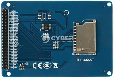
Interfacing a TFT_320QVT LCD/Touchscreen/SD to a Teensy 3.0

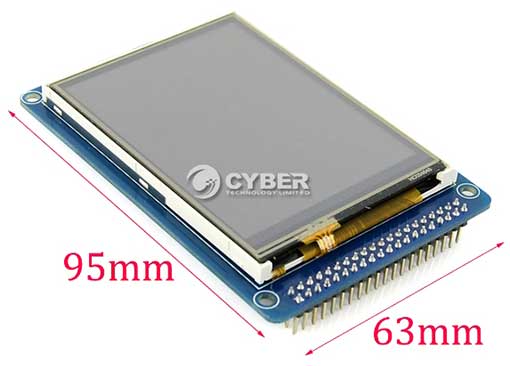
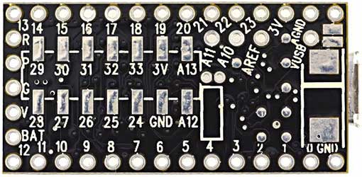
I’m working on a project which needs a touchscreen LCD. After searching eBay for a while, I noticed that many vendors were selling basically the same 3.2″ 320×240 TFT with resistive touchscreen and SD card reader. Though there were slight variations in the silkscreens, they all had the same model number – TFT_320QVT. I bought mine from digitalzone88 for $12.29. TK0466-1-digitalzone88 TK0466-4-digitalzone88 The board uses a SSD1289 LCD driver IC, and runs on 3.3V. The 3.3V voltage is incompatible with the typical Arduino, which runs at 5V (some vendors have created shields to interface it to an Arduino Mega). However, I purchased the TFT_320QVT with the intention of interfacing it to a Teensy 3.0, which runs at 3.3V. I noticed that there were not enough through-hole I/O pins on Teensy 3.0 to simultaneously interface to the LCD, touchscreen, and SD card. This necessitated the usage of the Teensy 3.0’s additional I/O pins, accessible only via solder pads on its underside: teensy3b To facilitate access to the 14 solder pads, I attached some header pins to piece of stripboard, and soldered 40AWG wire-wrap wire to between the pads and headers: extenderThe Teensy 3.0 runs on PJRC’s specially modified version of Arduino – Teensyduino. The task was to find compatible Arduino libraries. First order of business was the LCD. I searched the web, and found that dawnmist had spent a considerable effort in modifying Henning Karlson’s UTFT to work with the Teensy 3.0. Unbeknownst to me at the time, dawnmist’s modified UTFT is actually bundled with Teensyduino!
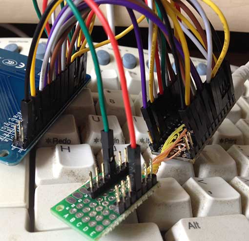
Next, was to get the touch screen working. It turns out that the current version of Henning Karlson’s UTouch is compatible with the Teensy 3.0.

For the SD slot, I tried the version of the Arduino SD library that’s bundled with Teensyduino. Unfortunately, though the SD library works with the TFT_320QVT’s SD reader, it stops working if you instantiate a UTFT object in the sketch. I tried sdfatlib, and found that not only does it work w/ the Teensy 3.0, but it coexists fine with UTFT. The only catch I found is that it works only with SPI_HALF_SPEED. When I set it to SPI_FULL_SPEED, it stops working.

Here is the Teensy 3.0 running UTFT‘s demo sketch on the TFT_320QVT: utft
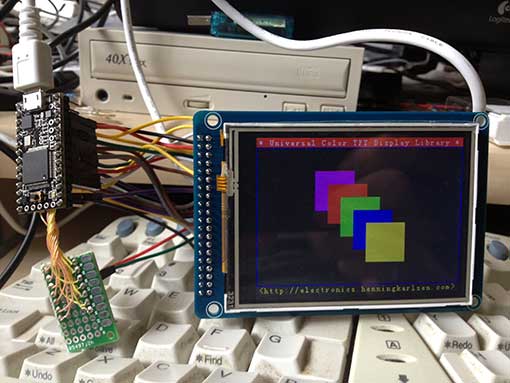
Below is the step-by-step procedure to getting the TFT_320QVT up and running with Teensy 3.0:

Step 1: Install the libraries

1. UTFT: Run the Teensyduino installer, and when the Libraries to Install dialog is displayed, check the box next to UTFT in the Choose Additional Libraries to Install combobox. (Note: Henning Karlson’s latest UTFT also works with Teensy 3.0, but my discussion below will show how to interface to the UTFT that’s bundled with Teensyduino 1.18).

2. UTouch: Download UTouch.rar. Use WinRar or 7-zip to extract the enclosed UTouch folder. From the Arduino IDE pull-down menu, use Sketch->Import Library->Add Library… to install the extracted UTouch folder. Alternatively, you can just copy Utouch/ to your arduinosketchbook/libraries directory.

3. sdfatlib: Download the latest version of sdfatlib. From the Arduino IDE pull-down menu, use Sketch->Import Library->Add Library… to install the downloaded sdfatlibyyyymmdd.zip file. You can alternatively just extract the SdFat/ folder into your arduinosketchbook/libraries directory.

Step 2: Wire it up

1. LCD: dawnmist‘s modified UTFT library that’s bundled with Teensyduino has a configuration file: arduinofolder\libraries\UTFT\hardware\arm\HW_Teensy3.h. Inside HW_Teensy3.h, there are 3 options for the LCD pin assignments: USE_B_D_PORTS, USE_C_D_PORTS, and USE_USER_PORTS. By default, the file has

#define PORTS USE_B_D_PORTS

enabled. USE_B_D_PORTS gives the best performance when your sketch needs to use SPI (which is needed for the SD card slot). USE_C_D_PORTS gives the fastest performance, but is incompatible with SPI. USE_USER_PORTS allows you to configure arbitrary pins (by changing the DB_0-DB_16 #defines), but results in the slowest performance. I elected to use the default USE_B_D_PORTS setting.

2. SD card reader: The SD card reader works via SPI, so it needs to use SD_DIN->DIN (MOSI – 11), SD_DO->DOUT (MISO – 12), SD_CLK->SCK (13), and one of the chip select pins, CS0-CS4 (10,9,20,21, or 15). I chose to use SD_CS->CS4 (15).

3. Touchscreen: The touchscreen uses 5 pins, T_DIN/T_DO,T_CS/T_CLK/T_IRQ, which can be assigned to any arbitrary free GPIO pins.

Below is a chart of my pin assignments:

Teensy_pin = TFT_320QVT_pin
0 = LCD_DB4
1 = LCD_DB5
2 = LCD_DB8
3 = LCD_LED_A (backlight)
5 = LCD_DB15
6 = LCD_DB12
7 = LCD_DB10
8 = LCD_DB11
9 = LCD_REST (RESET)
11 = SD_DIN (MOSI)
12 = SD_DO (MISO)
13 = SD_CLK (SCK)
14 = LCD_DB9
15 = SD_CS
16 = LCD_DB0
17 = LCD_DB1
18 = LCD_DB3
19 = LCD_DB2
20 = LCD_DB13
21 = LCD_DB14
22 = LCD_WR
23 = LCD_RS
24 = T_CLK
25 = LCD_DB7
26 = T_CS
27 = T_DIN
28 = T_DO
29 = T_IRQ
32 = LCD_DB6

LCD_RD needs to be pulled up to 3.3v

I have created a sketch, UTFT_UTouch_SdFat_teensy3, that simultaneously demonstrates the LCD, touchscreen, and SD card by modifying the UTouch demo sketch. Below are the lines which are critical to configuring it to work with the above pin connections:
[code language=”c”]
#include <UTFT.h>
#include <UTouch.h>
#include <SdFat.h>

// bitmap file to load as background.
// must be 320×240 and in format output by ImageConverter565
char bkgRaw[] = "ade.raw";

uint8_t sdCS = 15; // SD_CS – chip select
SdFat sd;
SdFile inFile;

uint8_t lcdRS = 23;
uint8_t lcdWR = 22;
uint8_t lcdCS = 4;
uint8_t lcdReset = 9;
uint8_t lcdBacklight = 3; // must be a PWM pin for variable brightness
uint8_t lcdBacklightBrightness = 255; // 0-255
UTFT myGLCD(SSD1289, lcdRS, lcdWR, lcdCS, lcdReset);

// Initialize touchscreen
uint8_t t_Clk = 24;
uint8_t t_CS = 26;
uint8_t t_DIn = 27;
uint8_t t_DOut = 28;
uint8_t t_IRQ = 29;
UTouch myTouch(t_Clk, t_CS, t_DIn, t_DOut, t_IRQ);
[/code]

The file displays a bitmap, ade.raw, as the background. Before running the sketch, copy ade.raw to a FAT-formatted SD card, and insert it into the TFT_320QVT’s SD card slot.

You can also substitute your own bitmap file. To create a .raw file, first create a 240×320 pixel jpg, png, or GIF file. Run it through either imageconverter565.exe (bundled with UTFT) or the online ImageConverter 565 make sure to select Convert to .raw file and Target Platform Arduino (AVR).

Here’s what UTFT_UTouch_SdFat_teensy3 looks like when it’s running:
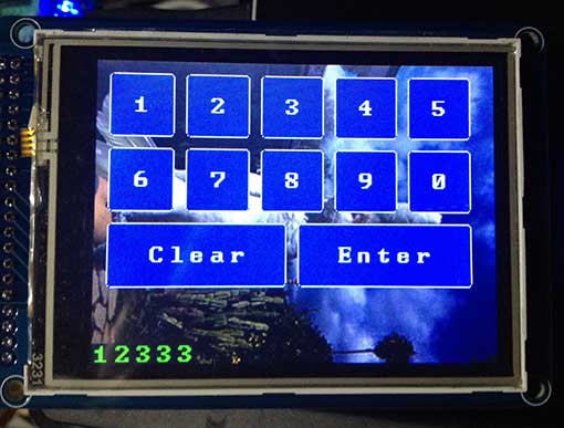
btntest

Many thanks to dawnmist, and the others who figured out how to get UTFT working with the Teensy 3.0.

Downloads:
UTFT_UTouch_SdFat_teensy3
UTFT_demo_tft_320qvt_teensy3

Links:
I obtained much of the information I needed from these pages:
dawnmist – screen working … finally
Teensy 3.0 – driving an SSD1289 with utft
ITEAD Studio IBOX Part 2: Booting up Debian Linux 7.0

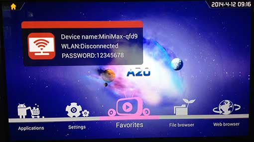
My IBOX came shipped with Android TV A20 pre-loaded in the NAND flash. I plugged a Microsoft keyboard and mouse into the USB ports, and used my Panasonic plasma TV as a HDMI display.  The boot screen is a bit confusing, because it implies that the device has WLAN support:
atv1

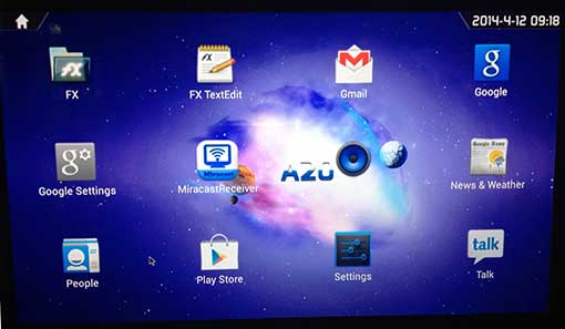
You can ignore the big WLAN banner on the screen, because the IBOX only has a RJ-11 100BT Ethernet port. The main screen has typical media center functions. Applications takes you into an Android launcher screen, Settings takes you to a typical Android settings screen. Going to the Applications screen shows that it has some typical apps pre-installed:

atv2

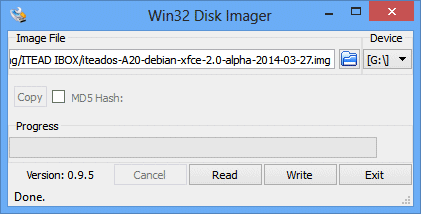
Most notable is the Google Play store support. I tried logging into Google Play and installing a few apps. They worked fine. However, I’ve heard that YMMV … some apps don’t work properly. Adobe Flash is also pre-installed, which is a plus. I did not play with it much, beyond some cursory tests, because I am more interested in running Debian Linux on the IBOX. ITEAD has a Debian 7.0 image, which runs off an SD card. Instead of downloading the version from ITEAD’s OS page, I used an alpha version built on 2014-03-27 which ITEAD sent me. To install it, first extract the  iteados-A20-debian-xfce-2.0-alpha-2014-03-27.img file from the downloaded.bz2 archive. I used WinRAR on my Windows machine to extract it. The image file needs to be copied to a 4GB or bigger micro SD card. Note that the .img file cannot be copied to a FAT-formatted SD card, because it contains an entire Linux filesystem. Instead, it must be raw-copied using a utility. In Windows, Win32 Disk Imager is a free utility that fits the bill:

w32diskimager

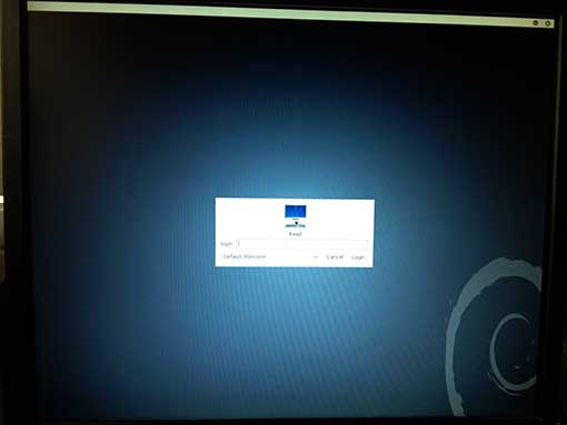
Simply select the image file and the SD card’s drive letter, and then click the Write button. After the image is successfully written, insert the microSD card into the IBOX, and power it up. If all goes well, you will first see two Linux Penguins in the upper left corner of the screen. After a while, the login screen should appear:

deblogin

Log in with user: root, password: root. While Android TV A20 was incompatible with my Dell LCD monitor (all I got was a blank screen), Debian 7.0 is working great. Unfortunately, I’m having the same problem with both my Dell LCD and my Panasonic plasma: when the screen blanks out after inactivity, I am not able to wake it up again. Therefore, I have to reboot it after every time the screen blanks. Hopefully, ITEAD will be able to tell me how to fix this.

Previous Article: ITEAD Studio IBOX – Part 1: First Look
Next Article: ITEAD Studio IBOX – Part 3: Installing Java and Processing

ITEAD Studio IBOX – Part 1: First Look

ITEAD Studio recently contacted me to let me know that they’re going to display my Lampduino project at the Shenzhen Makerfaire. I thought that was a pretty cool idea, and am honored to hear that. They also asked if I wanted to test out their IBOX mini multifunction single board computer, which is currently in its final days of its campaign on Indiegogo, having already raised over 4.5x its funding goal. The IBOX is designed with hackers in mind, and is driven by an Allwinner A20 ARM Cortex-A7 processor. Here are the salient hardware specs:

  • CPU Dual-core ARM Cortex-A7
  • GPU Mali 400 MP
  • DDR3 RAM 1GByte
  • NAND FLASH 4GByte
  • 4x USB
  • 1x HDMI
  • 1x optical S/PDIF
  • 1x 100BT Ethernet
  • 1x 7-24V DC power jack

ITEAD touts the IBOX as a very open hackers platform, capable of running a plethora of OS’s.  Currently, the following distros are available for booting from its onboard NAND flash:

  • Android TV A20 (from ITEAD)
  • Android 4.2 (from Cubietech)
  • Lubuntu (from Cubietech)

The following distros must be booted from the microSD:

  • Android SD bootable image (from LinkSprite)
  • Debian 7.0 (from ITEAD)
  • Cubian (from Liu)
  • Arch Linux (from archlinuxarm.org)

The IBOX comes in an anodized aluminum case that has a glossy plexiglas top:

top

Being a pre-production sample, I’ll excuse the fact that the top had a lot of superficial scratches on it, but I wonder if a matte surface would be better, since it scratches so easily. The left side of the unit contains a plethora of connectivity:

left

The small rectangle on the left labeled Uboot is a switch for entering the U-Boot bootloader. The right side contains a micro SD slot:

right

Behind the rectangular window is a 2-color status LED and an IR receiver for talking to remote controls. The back panel contains a 32-pin expansion interface connector:

back

The expansion connector is what really separates the IBOX from the typical ARM mini PC. It opens up the platform for hardware hackers, containing pins for UART, TWI, SPI, SATA, etc.  You can find the full pinouts on the Indiegogo page. The bottom of the IBOX is held on with 4 Philips screws:

bottom

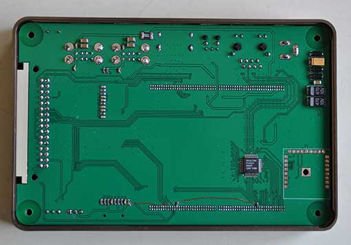
A set of rubber feet would be a nice addition.  Removing the metal bottom cover reveals the bottom of the baseboard:

botpcb

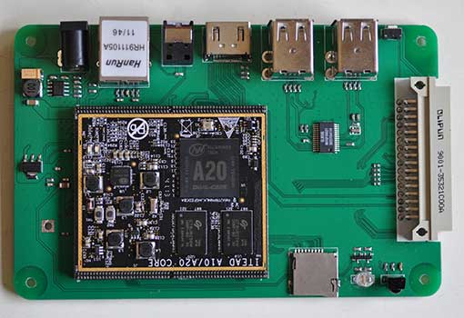
The baseboard is a very tight fit into the case.  In order to remove it, you must first pry the it away far enough to clear the various ports from their cutouts in left side of the case, and then pry upwards from the front.  The baseboard is a modular backplane which contains all of the I/O connectors, as well as the socketed core board:

pcbtop

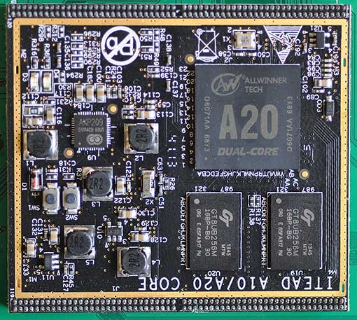
The core board is essentially the “brain” of the IBOX, containing the A20 processor, RAM, etc. Since the core board is socketed, it can be swapped out as newer, more powerful ones become available (e.g. A31, etc).  Here is a close-up of the A20 core board:

coreboard

Note that there are two pushbuttons, SW1 and SW2. I’m not sure of their purpose, but they are not accessible when the IBOX is assembled. The plexiglas top was attached to my IBOX with some rather messy clear silicone caulk:

inside

Again, I’ll excuse the mess because it’s a pre-production sample. I hope that the production units will have cleaner assembly.

So far, the IBOX looks like an interesting platform for building an energy efficient media center, file server, http server, etc. I’m looking forward to powering it up and putting it through its paces. Perhaps I will use it to replace my Raspberry PI that’s currently running XBMC. In my next article, I will boot up the IBOX, and test it out.

Resources:

Indiegogo campaign – the most information can currently be found on this page.
ITEAD blog – contains various informative posts on the IBOX
A20 core board schematic
IBOX baseboard schematic
IBOX baseboard design files
Case dimensions
distro downloads

Noritake 24×6 Character VFD Module

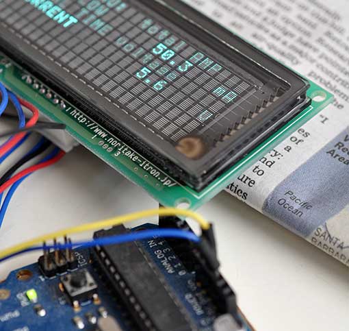
I’ve always thought VFDs were pretty cool. They used to be the rage in high end consumer electronics. Back in the mid 70’s, I built a VFD alarm clock. Recently, I got my hands on a modern VFD module to play with. The Noritake-itron SCK-Y100-24063-N14 is a very flexible 24×6 character VFD module in the same form factor of a 20×4 character LCD module. It is a member of Noritake’s CU-Y series VFDs.

vfdardu

Overview

  • 5V supply voltage
  • serial (asynchronous and synchronous) and 8-bit parallel communication
  • CMOS signal and RS-232 (+-15V) voltage compatible
  • jumper-selectable baud rate: 9600, 19200, 38400(default), 115200.
  • extensive built-in character sets: USA, European, Japanese (Katakana only), Multilingual – various fonts and symbols, Canadian and French, Nordic, WPC1252 – european fonts and symbols, Cyrillic, Latin, Portuguese, PC858 – european fonts and symbols
  • adjustable brightness
  • locally selectable brightness for highlighting (useful for implementing menus)
  • double width, and double width & height characters

The video below compares the Noritake 26×6 VFD to a 20×4 LCD. The characters are noticeably smaller on the VFD due to the higher density, but still quite readable.

This page shows some of the versatility of the Noritake VFD: Versatile Character Display CU-Y Series

The VFD comes pre-configured to operate in async serial mode at 38400 baud. It isn’t necessary to use a UART to talk to the VFD; any GPIO pins will suffice. A minimum of 2 pins are needed, for SIN (input) and SBUSY (output). A third GPIO pin can be connected to RESET (input). I hooked mine up to an Arduino UNO as follows:

D2 -> SIN
D3 -> SBUSY
D4 -> RESET

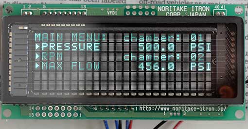
Here’s what it looks like from the front, running Noritake’s Arduino menu demo:

vfdfront

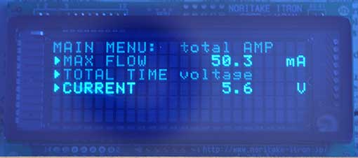
The lower contrast on the left side of the photo is due to my camera’s reflection – the glass is very reflective. Note the highlighting via localized variations in brightness. Here’s what it looks like with a blue filter on top (again, apologies for the reflections – it actually looks a lot better than this photo):

vfdblue

Though my photos are crap, the display is quite easy to read indoors. I wouldn’t recommend it for outdoor use, however, or anywhere that you expect direct sunlight.

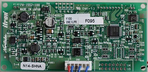
Back view:

vfdback

The 10-pin  jumper block on the top center is used for configuration, and the 14-pin jumper block on the bottom right is used only for parallel mode.

The writing speed of this VFD is very fast. Running in async serial mode on an Arduino UNO at 38400 baud, I was able to output 120 characters in a mere 38ms, which is about 3x faster than LiquidTWI2 can muster, even after the I2C bus is tweaked (and over 100x faster than LiquidTWI2 w/o I2C bus frequency tweaking). Unfortunately, Noritake’s Arduino library doesn’t compile on a Teensy 3.x, because it contains AVR assembly code in a timing function, and calls _delay_us(), which isn’t implemented on the Teensy 3.x. On the other hand, it should not be hard to replace these two functions. To use the Noritake VFD with Arduino, first download the Arduino code library. From the Arduino IDE’s pull-down menu, use Sketch->Import Library…->Add Library... to import Arduino_Noritake_VFD_CUY.zip. Include the following headers into your sketch:

[code language=”c”]
#include <CUY_Interface.h>
#include <CUY_Serial_Async.h>
#include <Noritake_VFD_CUY.h>
[/code]

Two classes need to be instantiated:

[code language=”c”]
CUY_Serial_Async interface(38400,2, 3, 4); // SIN,BUSY,RESET
Noritake_VFD_CUY vfd;
[/code]

Here is what initialization looks like:

[code language=”c”]
void setup() {
delay(500); // wait for device to power up
vfd.begin(24, 4); // 24×4 character module
vfd.interface(interface); // select which interface to use
vfd.isModelClass(Y100);
vfd.CUY_init(); // initialize the module
}
[/code]

Note that Noritake chose to implement only partial compatibility with the LiquidCrystal library.  So while vfd.print(s) is supported, vfd.setCursor(x,y) is not; one has to instead call vfd.CUY_setCursor(x,y). The Noritake_VFD_CUY class methods are declared in Noritake_VFD_CUY.h. Noritake includes a few sample sketches, which you can access from Arduino’s menu via File->Examples->CUY.

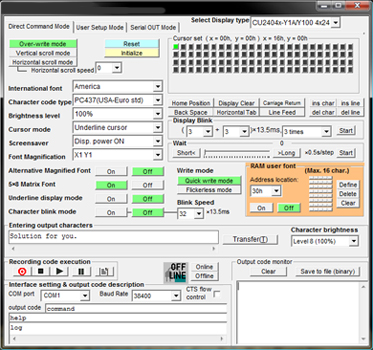
Noritake also provides a handy host program, which lets you configure and test the display without a microcontroller.

cue-y_373x350

To use the program, connect the VFD to a PC running Microsoft Windows via a Serial->USB adapter, such as an FTDI cable. Using the Serial->USB adapter opens up the possibility of using the VFD  as a USB auxilliary display for a PC.

The Noritake SCK-Y100-24063-N14 is a very cool device, and I’m looking forward to building a project with it.

Resource Links

SCK-Y100-24063-N14 Overview 
CU-Y: Y-Series Evaluation Software
Code Library
Arduino Library with examples
Sample C++ code and configuration/hookup
How to use custom fonts
How to use the built-in font tables
How to use the font magnification command
How to create a menu using the highlight effect

TL-WR703N: Adding Storage Space – EXTROOT

Once you have your TL-WR703N running OpenWrt, you’ll find that it doesn’t have a lot of free space for adding your own files. Here is the output from df from after installing attitude-adjustment:

root@OpenWrt:/# df -h
Filesystem Size Used Available Use% Mounted on
rootfs 1.1M 352.0K 736.0K 32% /
/dev/root 2.0M 2.0M 0 100% /rom
tmpfs 14.3M 56.0K 14.2M 0% /tmp
tmpfs 512.0K 0 512.0K 0% /dev
/dev/mtdblock3 1.1M 352.0K 736.0K 32% /overlay
overlayfs:/overlay 1.1M 352.0K 736.0K 32% /

Note how rootfs has only 736KB free.  Luckily, there’s an easy way to put your rootfs onto external storage (extroot), which lets you easily expand your root file system onto a USB flash drive. In the instructions below, I will illustrate how to implement the pivot overlay flavor of extroot.

First, format your USB flash drive with an ext4 filesystem. I used an old 512MB Crucial USB drive. If you are using Windows, MiniTool Partition Wizard Home Edition can easily create an ext4 filesystem on your USB flash drive.

Before you can mount the USB flash drive on your TL-WR703N, certain packages need to be installed.  ssh into your TL-WR703N, and issue the following commands:

opkg update
opkg install block-mount kmod-fs-ext4 kmod-usb-storage
reboot

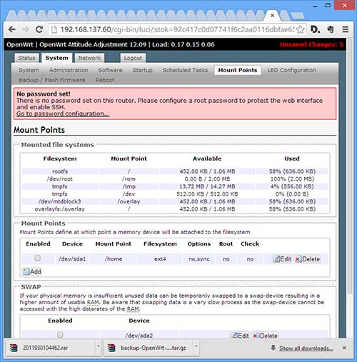
After OpenWrt reboots, access it via LuCI in your web browser, and navigate to the System->Mount Points tab. You should see a disabled mount point for /dev/sda1 as below:

mount

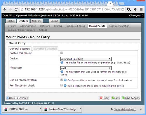
Click the Edit button and then check Enable this mount and Use as root filesystem:

extroot

Click Save & Apply, and then reboot OpenWrt.

If you don’t have LuCI installed, you can alternatively directly edit /etc/config/fstab. Add the following lines to the file:

config mount
  option device /dev/sda1
  option fstype ext4
  option is_rootfs 1
  option enabled_fsck 0
  option enabled 1

After your system reboots, if all is well, your USB drive will become your root file system:

root@OpenWrt:/# df -h
Filesystem Size Used Available Use% Mounted on
rootfs 462.3M 2.3M 435.4M 1% /
/dev/root 2.0M 2.0M 0 100% /rom
tmpfs 14.3M 48.0K 14.2M 0% /tmp
tmpfs 512.0K 0 512.0K 0% /dev
/dev/sda1 462.3M 2.3M 435.4M 1% /overlay
overlayfs:/overlay 462.3M 2.3M 435.4M 1% /

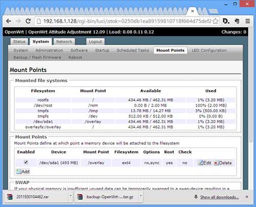
Note how rootfs/overlayfs now have 435.4MB free. From LuCI, it looks like this:

overlay


Related Articles: TL-WR703N

Hacking the TP-Link TL-WR703N – Part 2: Bring it back from the dead (How to unbrick it)

This morning, I realized that I actually had a 3.3V UART in my house that I could use to connect to my bricked TL-WR703N‘s serial port .. the Raspberry Pi runs on 3.3v! I dug up the instructions on how to hook it up on the OpenWrt forum. After hooking it up, configuring it, and firing up PuTTY, I found via the serial terminal output that OpenWrt was booting up just fine, but that the ethernet port was disabled. The problem is that mine has the newer bootloader which disables the LAN port:
U-Boot 1.1.4 (Mar 21 2013 – 10:09:10)

In my haste to flash it with OpenWrt, I missed the Gotchas in the OpenWrt wiki.  It turns out that my version of the TL-WR703N boots up with the ethernet port disabled, and the version of OpenWrt that I installed did not enable it. Fortunately, nebbia88 posted a special firmware which enables both the LAN port and WiFi by default, which I downloaded from dropbox (20170927: link is dead. download it here). The next step was to figure out how to get it loaded into my TL-WR703N. Unfortunately, the Raspberry Pi serial port was too flaky. It was printing out gibberish.

Method #1: Failsafe Mode

This is the easiest way to unbrick a TL-WR703N, because it doesn’t require any soldering, or even opening up the case. YOU DON’T NEED TO ACCESS THE TL-WR703N’s SERIAL PORT.  However, it will only work if your TL-WR703N will actually go into failsafe mode.

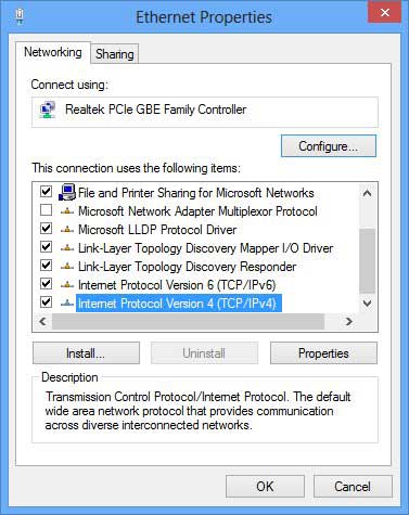
To get it into failsafe mode, power up the unit. The blue LED will flash once, and then go off for a few seconds. As soon as the LED turns on again, press the reset button. The LED should begin flashing very quickly, indicating that you are in failsafe mode. OpenWrt will always enable the ethernet port, and set its IP number to 192.168.1.1 when in failsafe mode. Next, set your host computer’s ethernet IP number to 192.168.1.2, and connect a CAT-5 cable between the TL-WR703N and the computer.  Instructions for this how to do this in Windows are below.

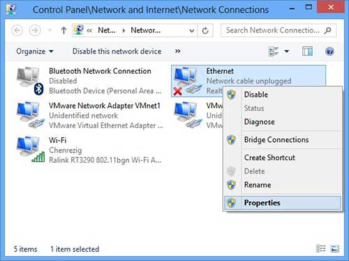
Step 1: open the Ethernet adapter’s property sheet:

properties

Step 2: double click on Internet Protocol Version 4:

ipv4

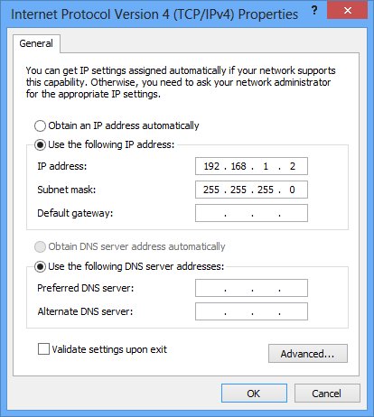
Step 3: Set your IP address to 192.168.1.2 and click OK:

ip

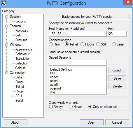
Step 4: Telnet to your TL-WR703N, in Windows, you can use PuTTY:

telnet
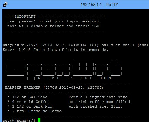
Step 5: After PuTTY connects, and you hit the enter key, you should be presented with the OpenWrt console:
console

If you cannot telnet into the TL-WR703N and get a console as shown above, then you will have to proceed to Method #2.

Before we can flash our new firmware file, openwrt-ar71xx-generic-tl-wr703n-v1-squashfs-sysupgrade.bin, we need to transfer it to the TL-WR703N.  One way to do it is to use nc, which is documented here, but I found it easier to use wget, which is also available in failsafe mode. First, we need to set up an http server on the host computer to send the file to OpenWrt.  onehttpd is a handy minimalist web server which can handle the task.  In Windows, simply drag and drop the folder containing your firmware file on top of onehttp-0.8.exe to launch the web server.

Step 6: Get the file into the TL-WR703N from the OpenWrt failsafe console, and the flash it in:

root@(none):/# cd /tmp
root@(none):/tmp# wget http://192.168.1.2:8080/openwrt-ar71xx-generic-tl-wr703n-v1-squashfs-sysupgrade.bin
root@(none):/tmp# sysupgrade openwrt-ar71xx-generic-tl-wr703n-v1-squashfs-sysupgrade.bin
root@(none):/tmp# reboot

After the unit reboots, you should be able to ping it at 192.168.1.1 via the ethernet port.

Method #2: Bootloader Mode:

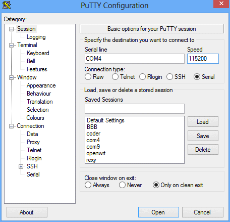
If you are not able to successfully enter OpenWrt failsafe mode, the bootloader is the only way to load the firmware. After hacking your TL-WR703N serial port, Connect your 3.3V UART->USB adapter to your host computer and connect to its virtual serial port using communication parameters: 115200,N,8,1. Open up your terminal program to connect to the virtual serial port. I used PuTTY:

puttyserial

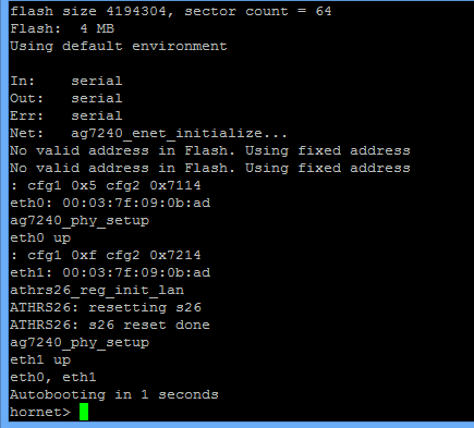
Power up the TL-WR703N, and type “tpl” (without the quotes) and then the enter key immediately after Autobooting in 1 seconds appears. If you do it correctly, you will get the hornet> prompt:

hornet

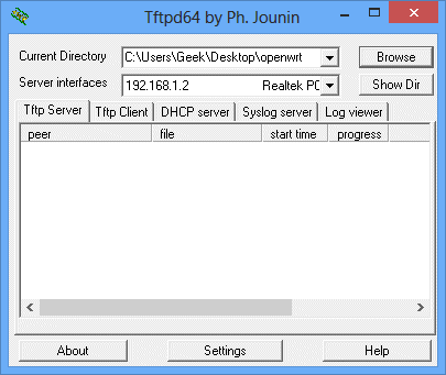
The timing is a bit tricky. If you fail, just power cycle the TL-WR703N and try again. You don’t need to reset your serial terminal between tries. The bootloader only supports tftp to receive the new firmware file. In Windows, tftp32 is a free server which works well. Download either the 32-bit or 64-bit version according to your version of Windows. Launch tftp32.exe (or tftp64.exe), set the Current Directory to the folder where your firmware file resides, and the Server interfaces to your ethernet adapter:

tftpd

From the hornet prompt in the serial console, issue the following commands:

hornet> setenv serverip 192.168.1.2
hornet> tftpboot 0x81000000 openwrt-ar71xx-generic-tl-wr703n-v1-squashfs-sysupgrade.bin
hornet> erase 0x9f020000 +0x3c0000
hornet> cp.b 0x81000000 0x9f020000 0x3c0000
hornet> bootm 9f020000

After it’s done running the commands, wait a few seconds, and power cycle the unit. After it reboots, you should be able to access the unit via its ethernet port.

Previous: Hacking the TP-Link TL-WR703N – Part 1: Brick it and then hack its serial port