RedBearLab BLE Shield – First Look

SeeedStudio was kind enough to send me a BLE Shield. Designed by RedBearLab and sold by SeeedStudio,  the BLE Shield is a convenient way to experiment with Bluetooth Low Energy on an Arduino.  Bluetooth Low Energy is a feature of the Bluetooth 4.0 specification, which is aimed primarily at low-power, low-latency wireless applications.

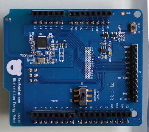
Here is a top view of the BLE Shield:

The tiny square SMT chip in the upper left is the Nordic Semiconductor nRF8001, a single-chip BLE connectivity IC.

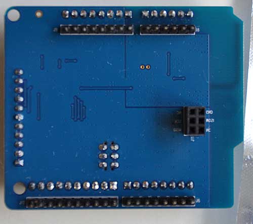
The pass through headers support the extra pins on the new Arduino Leonardo.  Currently, switch K1 should be left in the OFF position, as the OFF position is not supported.  The bottom of the board is not particularly interesting:

Note that it connects to the ICSP header, and that the pins are not extended through the top of the board, so if you want to stack it with a shield that also needs the ICSP pins, you will have to put the BLE shield on top.

Currently, BLE support on host devices is patchy at best.  On the Android platform, the Samsung Galaxy S3 contains a BT 4.0 hardware, but it’s currently not possible to program BLE, because the drivers are not yet available.

On Apple’s iOS platform, only the iPhone 4S/5, new iPad, and iPod 5th generation support BLE.  What’s nice is that there’s full support in the iOS SDK.  Unlike regular Bluetooth, for which very few profiles are available to the programmer in iOS (not even RFCOMM), you can easily design design your own custom BLE hardware and app.  What’s more, with BLE, you can avoid the expensive MFi hardware program, and simply submit your app for approval.

I am not sure what kind of SDK support is available in Windows, but I have ordered a cheap BT 4.0 dongle to try on my PC.

To program the Arduino, you must first download and install the BLE Shield Library.  To install the library, unzip the BLE and BluetoothLowEnergy folders into your <sketchbook>/libraries folder.  There is a sample BLEFirmata sketch in the BluetoothLowEnergy/examples folder.  It is compatible only with Arduino v1.0+.  The BLEFirmata sketch allows you to read/write the Arduino’s I/O pins from a remote device.  The current implementation of the library uses pins 8 and 9 for handshaking, so they are not available to your application.  Furthermore, communication with the board is via SPI (MISO/MOSI/SCK) pins.

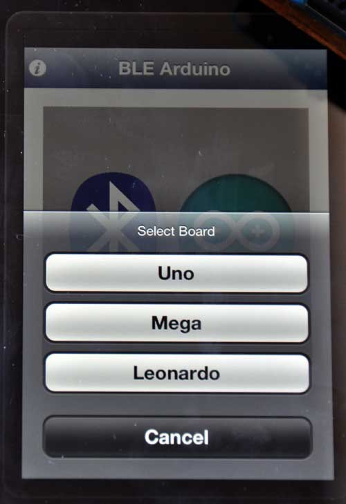
If you have a compatible iOS device, after loading BLEFirmata into your Arduino, you can go to the App Store, and download RedBearLab’s free BLE Arduino app.  I installed BLE Arduino on my iPad under iOS6.  When you launch the app and tap the Connect button, it automatically finds and connects to your BLE Shield. Unlike regular Bluetooth, you don’t have to go to Settings->General->Bluetooth and pair the devices (I wonder what happens if you have multiple BLE devices in the area, and how security is handled).  Once the app finds your BLE Shield, it prompts you for the type of Arduino it’s attached to:

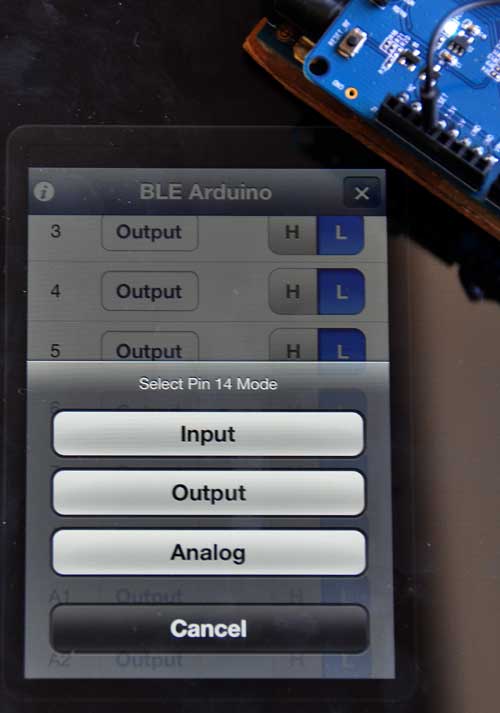
My Arduino Deumilanove is not listed as one of the options, but it works fine when you select Uno.  You can read or write any of the I/O’s in realtime.  If you select an analog pin, the app also gives you the option of treating it as analog or digital on input:

Here is the app displaying the value of pin A0 when configured for analog input, and the A0 pin is connected to the 3.3V pin:

Note that my USB cable is attached to the Arduino only to power it.

You can download the BLE iOS SDK and sample code from RedBearLab.  Their website also has lots of other documentation, as well as a forum for getting help.

I am looking forward to implementing some projects with the BLE Shield in the near future.
 

LeafCAN Hardware V2

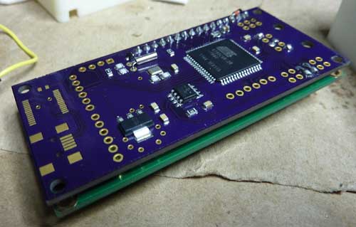
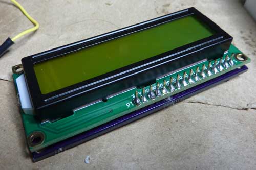
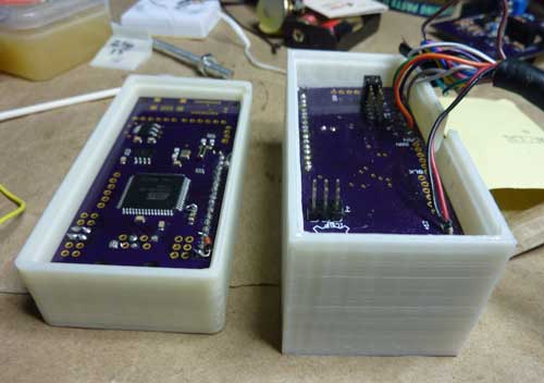
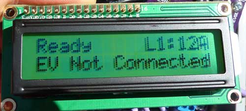
Chris H built and sent me a revised board for LeafCAN. The V2 board puts all of the components on the back of the board, instead of facing the LCD.  By also eliminating all of the header pins (except for the ones used to connect the LCD), the assembly becomes considerably thinner than V1:

Below are my V2 and V1 meters side-by-side.  The V2 meter is on the left:

The new circuit allows software control of the backlight, so I changed the firmware to turn off the backlight 5 seconds after CAN bus activity stops, and turn it back on when the activity resumes.

I also added a new feature, which I call “fixed fuel bars.” Recently, I noticed that the 12-segment fuel bar display in the Leaf’s dash is misleading and inconsistent. Even as your battery degrades, it always displays 12 bars at 100% charge, regardless of how much energy your battery can store. Over the course of 10K miles and 1 year of driving, my range has been dropping. Lately, I’ve been caught off guard, almost running down to turtle on 2 occasions, on a 66 mile drive that used to be easy. My SOC at 100% has dropped from 270 to 255 (I never got 281, even when the car was new). Another thing is, the car often only has the range with 3 bars remaining that I used to get with 2 bars remaining. So, I decided to make a new fuel display, which directly links the SOC and “fuel.”  On my fuel scale, 13 = 281 gids, and the transition from 0 -> 1 is at 24 gids, which corresponds to Very Low Battery.  The number is displayed with 1 decimal point.  I put the zero point at Very Low Battery, because when the charge gets this low, we really need more precision, and should be using raw SOC values.  Unlike the fuel bar display in the dash, the first bar contains as much energy as the rest.

I find it more convenient to use this new fuel gauge than SOC %, because I can easily do the calculations in my head while driving.  When driving, I’ll count the number of miles for it to drop by 1, and then multiply it by the remaining count.  For example, saw the car goes 8.3 miles when the “fuel” drops from 11.1->10.1.” Then I estimate that I can comfortably drive 80 miles given the current driving conditions.

Worst case for me is about 5 miles per fuel point, so when I want a conservative estimate of range, and I know I’m not going to be climbing any long, steep hills, I can just multiply the fuel number * 5 to estimate range.

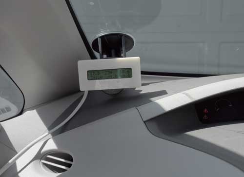
In the photo below, you can see I’ve rounded the corners on the new case, and the slimmer design looks nicer.  Also, I’ve switched to a 4-conductor white telephone cable, which is slimmer, and thin enough to squeeze in the gap between the left dash & the body.  I’m able to use only 4 conductors, because this build is hardcoded to use only the EV bus, so the only wires I need are power/ground/CANH/CANL.

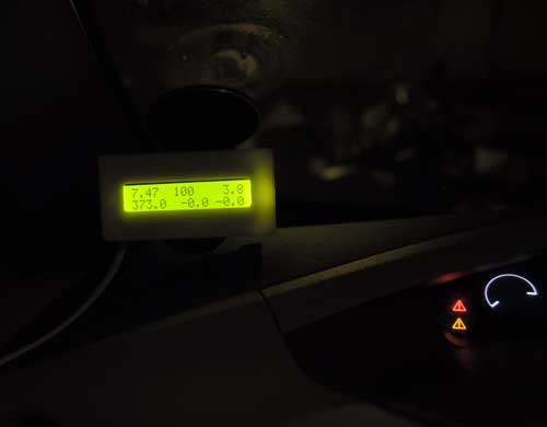
The top line displays:  remaining pack KWh/SOC in gids/remaining fuel

The bottom line displays: pack voltage/instantaneous amps/instantaneous power draw KW (pack voltage * amps / 1000).


As usual, the latest code is available on github, and you are welcome to modify the display code to suit your own tastes.

OpenSprinkler – An Open-source Internet-connected Sprinkler Controller with Web Interface

My house has a crazy amount of sprinklers.  In the front yard alone, there are 14 channels, which have been controlled by two very old Irri-Trol DewBee 7-channel units. I’m sure that they were fancy high-end stuff when they were purchased, but they look like they’re over 20 years old.  Not only were they a pain in the ass to program, but for the past year, they’ve been flaky, watering on the wrong days.  Another irritant is that they use a 9v battery backup which doesn’t last very long, so every time we have a long power outage, I’ve had to spend 1/2 hour reprogramming them.  It was high time for a replacement, but I couldn’t find anything that met my all of requirements at the hardware store:

  • easy to program
  • supports 14 channels
  • non-volatile program storage, so no reprogramming needed after long power outages
  • automatic clock setting after power outage
  • inexpensive

In addition, I thought it would be cool to be able to control it from the Internet, so I could change the settings if necessary, when away from the house.  I recently started playing with my Raspberry Pi, and was looking for a project to do with it, as a way to learn the ropes.  An Internet-connected sprinkler with a web browser interface immediately came to mind.  The RPi seemed perfect for the task, with its built in Internet connectivity, SD card, and tons of RAM.  One thing I’ve found with Arduino is that it’s easy to run low on memory when implementing web interfaces on it. No such problem with the RPi.  The RPi doesn’t have enough GPIO pins to handle my 14 channels + an LCD display, but I figured that I could cook something up with I2C.  The control aspect seemed  relatively easy to handle, but then I started thinking about how much work the web interface would entail.

Before starting on my own DIY sprinkler, I decided to search for existing open source sprinklers and happened upon Ray’s Hobby’s OpenSprinkler.  As soon as I saw it, I knew that I shouldn’t bother reinventing the wheel.  OpenSprinkler is an Arduino-compatible system with:

  • open source hardware and Arduino-compatible firmware
  • ATMega 328 MCU, 16×2 monochrome LCD, Ethernet, and onboard USBtinyISP
  • web-browser-based interface + direct HTTP interface for writing your own scripts
  • 8 channels, extensible in increments of 8 channels with extension boards
  • completely solid state, using 8 triacs instead of relays

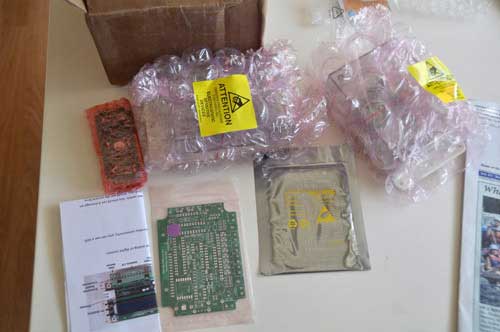
Since I needed 14 channels, I ordered a DIY OpenSprinkler 1.4u kit ($89.99) and an extension board ($25.99).  Pre-assembled SMT boards are also available at higher cost. Shipping was very fast, and I received a box a few days after I placed the order.  The kit came nicely packaged, with bubble wrap protecting all of the delicate parts:

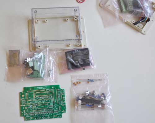
The components were also bagged in separate groups, which made finding the parts easier:

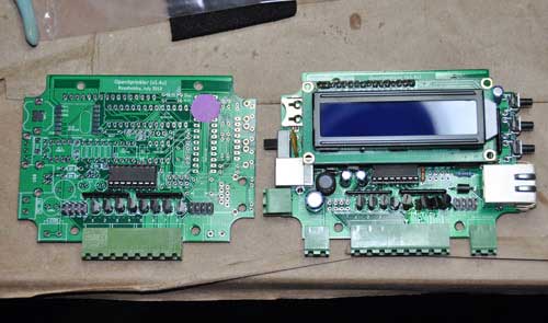
Ray’s Hobby has great documentation on their website.  The step-by-step assembly instructions are very clearly written, with lots of photos, and easy enough for even a noob to follow.  It took me about 3.5 hours to assemble both the main board and extension board, and one hour of that was spent undoing a careless error on my part.  I inadvertently soldered 4 of the triacs on the main controller board backwards, and had to clip the leads and solder them onto the top of the PCB in order to reverse the connections.  You can see in the photo below that the rightmost 4 triacs are all askew due to my messy rework:

The kit doesn’t come with a 24V transformer, so I salvaged one from one of my DewBees.  The firmware is completely open source Arduino code, and is hosted on github.  The controller has a built-in USBtinyISP, so you don’t need an FTDI cable or programmer to load the firmware.  It comes preloaded with the latest release, so I didn’t test uploading new firmware yet.

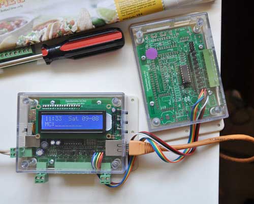
Ray takes the cautious approach, walking the user through inserting only the switching regulator and testing the power supply voltages before inserting the remaining IC’s.  After verifying the 5V and 3.3V supply voltages, I inserted the rest of the IC’s and to my delight, the unit powered up flawlessly on the first try:

The unit has a test mode that is entered by pressing and holding the top button while powering up.  In test mode, it cycles through the channels, turning each one on for 5 seconds.  I tested the triacs with a voltmeter, and was happy to find that I hadn’t fried any of them or messed up any PCB traces while doing my rework.

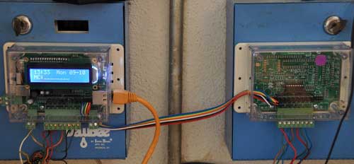
I mounted the units on top of my existing controllers by simply sticking them on with double-sided foam tape:

This way, I can revert to the old controllers when I sell my house.  I’m not sure if the new owners will be savvy enough to figure how to connect it up to the Internet, figure out the IP number mapping to the unit, and then pull it up on a web browser.

For Internet connectivity, I’m using an old Linksys WRT54G in running DD-WRT in wireless repeater bridge mode.  An added benefit is that I can now use my house’s WiFi from my driveway, where the signal was previously too weak.    I have my router set up to assign a fixed IP to the OpenSprinkler.  If you forget the IP number, pressing the 2nd button displays the current IP number and TCP port.

The web interface is a bit quirky, but it’s easy to use once you figure it out, and has  a terrific graphical preview screen.  The preview screen is actually one of the features that really sold me on OpenSprinkler, because it makes it very easy to check your programming for errors:

Ray cleverly gets around the limited memory of the ATMega328 MCU, and avoids having to have an onboard SD card by hosting a bunch of javascripts on his own webserver.  This means that in order for the web interface to function, the unit must have Internet connectivity.  You can host the scripts on your own LAN if you wish, but then you need to have a webserver running at all times.

I’ve only OpenSprinkler running for a couple of days, but so far, it’s running flawlessly.  I am very impressed with the quality of Ray’s Hobby’s products and detailed documentation, and would definitely recommend them to my friends.  Ray is actively working on improvements to the firmware, and since it’s open source, I’m able to hack it any way that I please.

Teensy 3.0

I just backed the Teensy 3.0 on Kickstarter.  It’s designed by Paul Stoffregen, the same wizard behind the Arduino-compatible Teensy boards.  It sports a 32-bit ARM Cortex-M4 chip, and is programmable via Arduino and C.  This looks like it’s going to be a great platform for building embedded projects that need more power than the typical Arduino.  The board is tiny compared to Raspberry Pi.

Technical Specs:

  • 32 bit ARM Cortex-M4 48 MHz CPU (M4 = DSP extensions)
  • 128K Flash Memory, 16K RAM, 2K EEPROM
  • 14* High Resolution Analog Inputs (13 bits usable, 16 bit hardware)
  • 34* Digital I/O Pins (10 shared with analog)
  • 10 PWM outputs
  • 8 Timers for intervals/delays, separate from PWM
  • USB with dedicated DMA memory transfers
  • 3 UARTs (serial ports)
  • SPI, I2C, I2S, IR modulator
  • I2S (for high quality audio interface)
  • Real Time Clock (with user-added 32.768 crystal and battery)
  • 4 general purpose DMA channels (separate from USB)
  • Touch Sensor Inputs

At $22, it’s a bargain.  The campaign ends on Sept 16, so get them while they’re hot!

How to use a WiFi Dongle with Raspberry Pi

My house isn’t wired for Ethernet, so I needed to get my Raspberry Pi networked via WiFi.  USB WiFi dongles are cheap, and can easily be found for less than $10.  I just happened to have an Airlink101 AWLL6075 laying around.  By coincidence, it uses the RTL8191SU chipset, and the official Raspbian distribution is preloaded with the appropriate driver (module r8712u).

USB WiFi dongles use quite a bit of current, and some web references said that they could only be used with the RPi via a powered USB hub.  However, some people reported success without the hub.  I couldn’t find a working powered USB hub in my house, so I tried connecting my dongle directly to my RPi.

While googling around for instructions on how to configure Raspbian for my WPA2-PSK network,  I found several different sets of instructions for configuration, and none of them worked.  After wasting a whole afternoon with no luck, I found out that early RPi boards had 140mA polyfuses to limit current draw on the USB ports. In addition to limiting the current too severely, the polyfuses lower the voltage below spec.  Therefore, later boards have 0 ohm resistors instead of the polyfuses.  Here is an official blog post which shows that the later boards don’t have the fuses:  http://www.raspberrypi.org/archives/1929

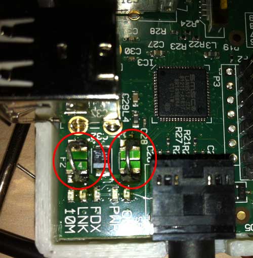
The fuses in question are F1 and F2.  The polyfuses are green, and have 14 written on them.  The 0 ohm resistors are black.  If your RPi has the resistors, then you don’t need to modify it. My board had the polyfuses, so I shunted them by soldering in jumper wires:

Bingo! The WiFi fired right up and connected to my AP on the first boot after the fix.

The easiest way to configure the SSID and password for your network is to edit the file /etc/network/interfaces:

$ sudo nano /etc/network/interfaces

Add the following lines to the file:

auto wlan0
iface wlan0 inet dhcp
wpa-ssid “YOURSSID”
wpa-psk “YOURPASSWORD”

Substitute your network’s SSID and password in the quotes above.  If present, remove the 70-persistent-net.rules file:

$,sudo rm /etc/udev/rules.d/70-persistent-net.rules

Upon rebooting, your WiFi should connect up automatically.  If you want to start it without rebooting, type

$ sudo ifup wlan0

Here are some useful commands related to your WiFi configuration:

$ iwlist wlan0 scan

scans for and displays available WiFi networks.

$ iwconfig

shows WiFi connection info, such as ESSID, bit rate, and frequency.

$ ifconfig

displays network information, such as IP number, MAC address, and packet errors.

SLA (Stereolithography) First Printing Attempt with 405nm Laser Curing UV Resin

olio & I are working on SLA (stereolithography) printing using lasers, rather than a DLP projector.  The goal is to print with either a polygon mirror assembly as is currently found in laser printers, or a galvanometer, such as is used in laser light shows.  For initial tests, we are using a 100mW blu-ray laser diode.  While waiting for some B9 resin, which cures with visible light, on a lark, we decided try curing some Bucktown 385nm UV resin.  Surprisingly, it cures easily with a 405nm laser.

Today, we decided to try printing a test object on olio’s aluminum x-y bot with gcode generated by slic3r, sending it to Marlin firmware running on the bot, via Repetier-Host.  We arbitrarily chose a 15 mm/s feedrate.  We don’t yet have a way to turn the laser on and off, so instead, we just did fast moves at 150 mm/s.  I wasn’t expecting any sort of success, but amazingly, the first print was somewhat successful!

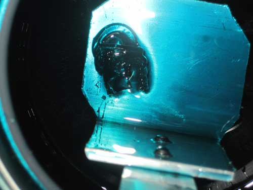
After draining the resin vat, it looked like all we had was a gunky blob:

Upon closer inspection, we were pleasantly surprised to find that it actually was a reasonable facsimile of our object, but it was so soft that it broke in half even with careful handling:

Though the print wasn’t entirely successful, I’m amazed that it worked at all! Obviously, there’s a lot of tweaking to be done, but it’s a good start.

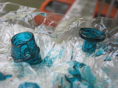
Here’s a Reprapped print of the same object:

It’s 15mm in diameter.

Cheap 16×2 LCD Comparison

HD44780-compatible 16×2 LCD’s are cheap (<$4), and easy to use with Arduino via the LiquidCrystal library. To reduce the pin count considerably, the Adafruit LCD backpack is a nice little add-on that converts them to work via a two-wire I2C or SPI interface.

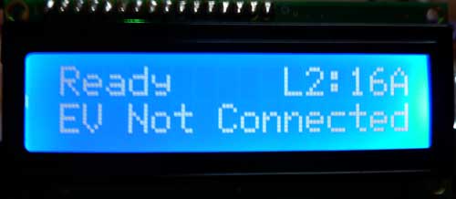
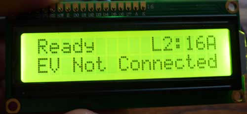
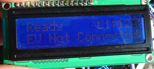
I bought two types to compare for use with OpenEVSE and LeafCAN. One has white lettering over a blue background, and the other one has black lettering over a yellow background. Here is an indoor comparison:

My camera can’t take good photos of the blue LCD indoors. The blue background is actually a good bit darker than in the photo, and the contrast is much better than it appears. Factoring that in, I guess I would still give the yellow LCD a slight edge indoors.

Now, here they are outdoors, in direct sunlight:

Again, the blue LCD didn’t photograph well. It looked slightly better than depicted in the photo. However, it’s a clear win for the yellow LCD. It works as a reflective LCD in direct sunlight, with very high contrast.

Marlin Tuning

To get the most out of Marlin, here are a few simple tweaks.

1. EEPROM Settings

By default, Marlin forgets any configuration changes you make via the Mxxx G-codes whenever you reset or power cycle your controller. If you want to remember the settings, so you don’t have to set them every time you power up your controller, Marlin can store them in EEPROM. In Configuration.h, uncomment

#define EEPROM_SETTINGS

EEPROM_CHITCHAT is optional:

//to disable EEPROM Serial responses and decrease program space by ~1700 byte: comment this out:
// please keep turned on if you can.
#define EEPROM_CHITCHAT

You will need to compile Marlin and then upload the modified firmware to your controller in order to take advantage of the changes.

After sending your Mxxx G-codes to Marlin, send M500 to save them to EEPROM.  You can also revert to default (“factory settings”) with M502.

One nice feature of Repetier-Host is that you can use it to set your EEPROM, rather than manually typing in Mxxx G-codes.  Simply go to Config->Firmware EEPROM Settings from the menu.

Personally, I prefer to just set all my Mxxx G-codes as start G-codes in Slic3r, rather than storing them in EEPROM, but most people will probably prefer to use EEPROM.

2. PID Auto Tune

When I first switched to Marlin, I was not at all happy with the temperature control of my extruder.  It was taking a long time for my hot end to heat up, and the temperature was still varying a lot. While the hot bed is controlled using bang-bang (traditional on/off temperature control), the extruder uses a more sophisticated algorithm, called PID, which should yield better temperature stability.

Initially, I tried turning off PID by commenting out

#define PIDTEMP

in Configuration.h.  My hot end heated up much faster, but the temperature was still fluctuating a lot.  I decided to try to get PID working better.  In order to get best performance out of PID, there are some parameters which need to be tuned: Kp,Ki, and Kd.  Configuration.h contains settings for Ultimaker, Makergear, and Mendel Parts hot ends, but I’m using a JHead.  I had no idea what values to use for After doing a bit of googling around, I found out that Marlin has a way for it to automatically calculate PID parameters, G-code M303 – PID relay autotune.  To automatically tune your hot end PID parameters, start with your hot end at room temperature, and using Pronterface, send it the M303 G-code as follows:

M303 S230

The parameter is the target temperature in celcius.  If your target temperature is different, substitute it for the 230.   Marlin will then heat up and cool down your hot end, while taking measurements.  This will take a while.  When it’s done, it will output a message similar to this one:

bias: 103 d: 103 min: 147.98 max: 152.02
Ku: 65.06 Tu: 30.67
Clasic PID
Kp: 39.04
Ki: 2.55
Kd: 149.66

Next, you need to tell Marlin to use the calculated Kp, Ki, Kd values.  If you don’t want to hassle with compiling/reloading Marlin, you can just use the M301 – Set PID parameters P I and D G-code.  Using the my values above, it looks like this:

M301 P39.04 I2.55 D149.66

I simply added the line to my start G-code in Slic3r.  Setting the PID parameters in G-code allows you to change them on the fly for different profiles, for instance, if you like to switch back and forth between PLA and ABS.

If you prefer to hardcode the values as defaults in the firmware, set them as follows in Configuration.h:

#define  DEFAULT_Kp  39.04
#define  DEFAULT_Ki 2.55
#define  DEFAULT_Kd 149.66

3. Acceleration and Jerk

If your printer vibrates a lot when printing at higher feedrates, causing wiggly prints, you can improve the quality without slowing down your prints too badly by lowering the acceleration and/or XY-jerk values. In Marlin, acceleration is specified in mm/s^2. The default is 3000. On my Printrbot, I slowed it down to 1000 with G-code as follows:

M201 X1000 Y1000; // max accel print
M202 X1000 Y1000; // max accel travel
M204 S1000; // default accel for normal moves

You can also change the value in Configuration.h, if you prefer:

#define DEFAULT_ACCELERATION 1000 // X, Y, Z and E max acceleration in mm/s^2 for printing moves

If you have a slow extruder, you can also slow down the retraction acceleration, but generally, there’s no reason do do this:

#define DEFAULT_RETRACT_ACCELERATION  3000   // X, Y, Z and E max acceleration in mm/s^2 for r retracts

3000 is the default value.

The jerk value is also useful, and affects the speed at which Marlin joins two segments. The default XY-jerk value is 20 mm/s.  Lowering the value will slow down the transitions between segments.  This is especially helpful for smoothing out ringing waviness on 90 degree turns.  I found that 15mm/s is a good balance between speed an quality on my Printrbot.  G-code:

M205 X15; // max xyjerk mm/s

Configuration.h:

#define DEFAULT_XYJERK                20.0    // (mm/sec)

There are also values for the z-axis and extruder, but I didn’t need to change them:

#define DEFAULT_ZJERK                 0.4     // (mm/sec)
#define DEFAULT_EJERK                 5.0    // (mm/sec)

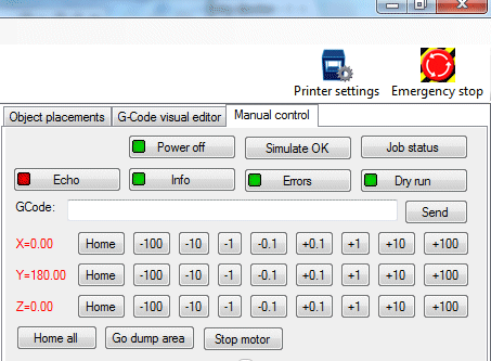
When tuning acceleration and jerk values, a handy way to test the effects of your new settings is the Dry Run feature of Repetier Host.  When Dry Run is enabled, the extruder is disabled while printing, so you can observe its motion without wasting filament.

After tuning the acceleration and jerk values my prints are better quality at higher feedrates, without sacrificing too much speed.  Note that depending on your print, the lower acceleration/jerk values will have more or less effect on the total time it takes to complete it.  Prints that have more short segments will be slowed down a bit more.

Even though my discussion was about slowing down the printer, you can also tune the acceleration/jerk parameters to speed things up, if you have a particularly well-tuned bot.

Colorduino Library v1.2.3 Released

Thanks to wiltwong and Markus Lange, I have added support for Arduino Mega and Leonardo to the Colorduino Library.  Markus also helped to clean up the code a bit for Arduino 1.x.  I have added the ColorFill() function to the ColorduinoObject class, as well, so you don’t have to copy it from ColorduinoPlasma.pde.

You can download it from github: https://github.com/lincomatic/Colorduino/downloads