grbl CNC Firmware Ported to Printrboard

If you want to use your RepRap for CNC use, such as milling PCB’s, regular 3D printing firmwares might not be ideal. For instance, Marlin is not able to handle the slow step rates used for CNC work.

I have ported grbl, a firmware specifically for CNC use (from which Marlin derived its acceleration routines), to Printrboard and Teensylu. You can download it from my fork at: https://github.com/lincomatic/grbl.

Repetier Firmware Now Runs on Printrboard

I spent this past weekend porting Repetier-Firmware to Printrboard and Teensyduino. It took me a while to get it working properly, because the code intermixes calls to fastio and Arduino, and the pin definitions in fastio.h were different from the Teensyduino Arduino library. It is now working pretty well, so Printrboard and Teensylu users now have yet another option for RepRap firmware. I’ve already submitted my changes to Repetier, and he’s merged them into his code. Download it here: https://github.com/repetier/Repetier-Firmware.

In case you haven’t tried it, Repetier also has an interesting host program, Repetier-Host, which works with other firmwares as well as Repetier-Firmware.

Running Marlin Firmware on a Printrboard

As of this writing, the official version of Marlin firmware from github does not yet work with Printrboard.  Printrboard is a fork of Teensylu, designed by the folks at Printrbot. Printrboard isn’t yet available for purchase, but since the design is open source, anyone can download it and get the PCB’s manufactured themselves. Sprinter is currently the only RepRap firmware works with Teensylu and Printrboard out of the box.  I am now successfuly running Marlin on my Printrboard.  Below is a video of Printrboard virtually printing a Printrbot with Marlin:

Last month, I submitted an issue with ErikZalm to get the compile errors fixed when compiling Marlin for Teensylu.  The main branch of Marlin now compiles for Teensylu by setting MOTHERBOARD = 8.  Unfortunately, this build setting won’t work with Printrboard, because some of the pins are different.  Also, there is a kill function that Marlin calls if it detects certain things like a shorted thermistor, etc… but it’s not able to send the error messages back to the host, so it looks like your board is just dead.
I think Erik is too busy right now getting V1 out the door to deal with making fixes for a couple of not so popular boards, so I’ve forked Marlin on github with my fixes for making it behave nicely with Teensylu and Printrboard.  You can download it here:  lincomatic/Marlin.
——————————–
For Firmware Hackers Only
For those who want to know what’s special about my branch of Marlin, it has to do with the mappings of the I/O pins.  The code in Marlin has two different ways to access digital I/O pins: 1) the Arduino digitalRead/Write() functions 2) fastio – there are macros and pin assignments in fastio.h.  In ErikZalm’s Marlin branch, the pin numbers are different between Arduino and fastio functions, which leads to confusion and bugs.  What I have done is use the digital pin definitions in Teensyduino’s core_pins.h and updated the pins in fastio.h to match them.  This way, a call to digitalRead(28) is equivalent to _READ(28).
EXECEPTIONS:
  1. in pins.h, analog pins use ADC numbering instead of digital pin numbering.  Therefore, even though B_THERM -> F0/ADC0 and E_THERM -> F1/ADC1, we are using them as ADC pins, so B_THERM=0 (ADC0) and E_THERM=1 (ADC1).
  2. Printrboard uses some pins that aren’t supported by Teensyduino, since they aren’t exposed in the Teensy hardware.  Therefore, those pins aren’t listed in core_pins.h.  I have added them to fastio.h, so they are accessible only with fastio macros.  They are digital pins 46 and 47 see the “//– Begin not supported by Teensyduino
    ” section of fastio.h

EXAMPLES:

XSTEP = physical pin 51. Looking at the AT90USB1286 spec sheet, pin 51 = PA0 (AD0)
in core_pins.h, #define PIN_A0 28
in fastio.h,

#define DIO28_PIN PINA0
#define DIO28_RPORT PINA
#define DIO28_WPORT PORTA
#define DIO28_PWM NULL
#define DIO28_DDR DDRA

so in pins.h, X_STEP = 28

X_MIN = AT90USB1286 pin 9 = PE3
core_pins.h doesn’t have a definition for PIN_E3, because the pin isn’t accessible in Teensy++, so we can’t talk to that pin at all with the Arduino functions.  However, it’s in fastio.h:

//– Begin not supported by Teensyduino
//– don’t use Arduino functions on these pins pinMode/digitalWrite/etc
#define DIO47_PIN PINE3
#define DIO47_RPORT PINE
#define DIO47_WPORT PORTE
#define DIO47_PWM NULL
#define DIO47_DDR DDRE

so X_MIN = 47

RepRap – 3D Printing Project Kickoff – Printrboard First Look

I have been somewhat intrigued by the RepRap project, an open source 3D printer movement, for several years.  However, wasn’t motivated enough to jump into the fray until late last year, when I saw Brook Drumm’s Printrbot on Kickstarter.

With only about 1 hour left before funding closed, I pledged $500 to get a Printrbot kit. While I could have started from scratch, and built a Prusa Mendel, after reading about how much tweaking is involved in building and setting up a RepRap, I decided to start with a Printrbot – a cute, compact, and simple design, and the most inexpensive RepRap at the time.  Printrbot’s Kickstarter was a smashing success.  They raised an astonishing $830K. Unfortunately, the gigantic amount of orders they received means that mine will take a little longer to get to me than I originally anticipated. So, I’ve been immersing myself in the intricacies of the electronics, firmware, host software, and mechanical aspects of RepRap for the past couple of months.

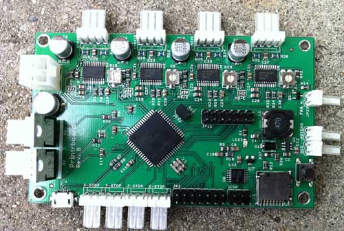
There are a variety of popular controller electronics for RepRap, the most popular being RAMPS.  The electronics are one of the largest costs of building a RepRap.  Although RAMPS is convenient, because it’s based on an Arduino Mega, I like the idea of having a single dedicated board.  The Printrbot folks have designed their own controller board, which they call Printrboard.  Although Printrbot is not yet selling Printrboards, the design is open source, and thus, I was able to obtain one before their release.

Kang, a fellow RepRapper from Seoul, Korea, built a few Printrboards and sent me one to play with.

Printrboard is a fork of Teensylu, an AT90USB1286/AT90USB1287 based RepRap controller.  I like the fact that these boards are based on the AT90USB128x MCU’s because they have built-in full USB support, eliminating the need for an external serial->USB bridge IC; additionally, the native USB support means that communication with the host computer is blazingly fast – 12Mbps rather than 115200kbps.

There are a few notable differences between Printrboard and Teensylu.  Printrboard is a single board solution.  First, Printrboard adds an integrated SD card reader.  This is handy for printing while untethered to a computer.  Teensylu has I/O pins which can be used to easily add an SD card reader.

Second, the stepper motor drivers are integrated onto Printrboard’s PCB, while Teensylu uses plug-in Pololu/Stepstick carriers.  The advantages of integrating the stepper drivers onto the main PCB are reduced cost and compactness.  The downside is that it is not uncommon to blow up a stepper driver IC, so having them soldered in means if one goes bad, the whole board is unusable.

Third, Printrboard uses Allegro A4982’s in a 24-TSSOP package, while Pololu/Stepstick use the Allegro A4988 in a 28QFN package.  The TSSOP package is considerably larger, and has a wider pin pitch, which makes reworking the board easier if one of them blows out; the 28QFN is very tiny and not for the faint of heart.  The other difference between the A4982 and A4988 is that the A4982 only supports full/half/quarter/sixteenth stepping, while the A4988 also supports one eighth stepping.

Some other minor differences between Printrboard and Teensylu are that while Printrboard only supports a 12V2 ATX power input, Teensylu gives more power options.  Also, Teensylu has a large USB-A socket, while Printrboard uses a micro USB-B socket.

I am diving into figuring out how to load Marlin RepRap firmware into Printrboard/Teensylu, to keep my end of the bargain with Kang.  A series of articles will follow with my findings.

AVR CAN Bus Project: Step 4 – LeafCAN: Nissan Leaf SOC Meter

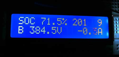
I have implemented a SOC (State of Charge) meter for the Nissan Leaf. Many thanks to garygid and others from the MyNissanLeaf forums, for their help in decoding the Leaf CAN bus messages, and figuring out the pinouts.

The top line shows the SOC%, raw SOC value, and number of charge bars displayed in the dash.
The second line shows battery pack voltage and current in amps.

You can download the Eagle CAD schematic and AVR (Arduino) code from github:  lincomatic / LeafCAN
The Eagle schematic uses the Sparkfun library.

The schematic shows how to implement the entire circuit, without using the Olimex AT90CAN128 breakout board.

My original intent was to make a small PCB that directly attached to the LCD, and put it into a small case, but I never got it past the breadboard stage.  Unfortunately, I have gotten busy with other projects, so I am probably not going to do further development on this device nor finish the PCB layout, unless there is a large amount of interest. However, feel free to adapt it as you wish for your own CAN bus projects. Do bear in mind, however, that the design is licensed via the GPL, so if you use it for a commercial project, you must openly share your design.

Previous: AVR CAN Bus Project – Step 3: CANspy CAN Bus Monitor
Next: LeafCAN v1.1 Released

AVR CAN Bus Project – Step 3: CANspy CAN Bus Monitor

Sorry for the delay in posting the circuit and schematics from my AVR CAN Bus Project – Status Update 1.  The circuit for interfacing the Olimex AT90CAN128 Header Board is incredibly simple, and only requires 3 components.

Parts List
(1) .1uF ceramic capacitor
(1) 10K resistor
(1) Microchip MCP2551 CAN transceiver

Schematic

If you’re going to connect it to a Nissan Leaf, the car has 3 different CAN buses accessible via the OBD-II connector. The pinouts can be found on MyNissanLeaf.com in this thread: Leaf CANbus Decoding (Open Discussion)

To communicate with the AT90CAN128 header board from my PC, I connected a USB to serial converter to USART0: TXD0 (pin 3) and RXD0 (pin 2).

Arduino Sketch

Below is my CANSpy sketch for monitoring the CAN bus via the serial port, as depicted in my Status Update 1.

Download: CANspy.zip

To compile the sketch, follow the instructions in AVR CAN Bus Project – Step 1: Programming AT90CAN128 with Arduino.

In my next update, I’ll show how to implement a SOC (State of Charge) meter for the Leaf using a LCD display.
Previous: AVR CAN Bus Project – Status Update 1
Next: AVR CAN Bus Project: Step 4 – Nissan Leaf SOC Meter

AVR CAN Bus Project – Status Update 1

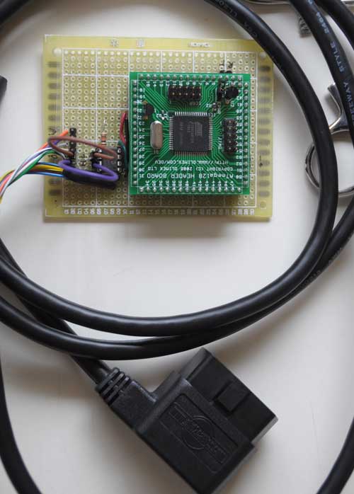
I got the circuit wired up yesterday:

The 6-pin jumper on the left lets me select one of the 3 CAN buses on the Nissan Leaf accessible via the OBD-II connector.

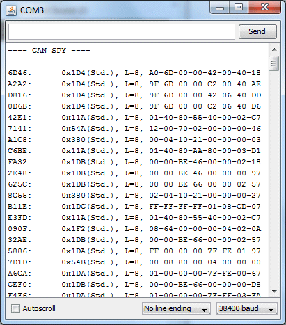
I hacked up some code quickly, and was pleasantly surprised that it actually worked! Woohoo! The part I thought was going to be most difficult – getting the CAN interface firmware working – turned out to be the easiest. Here’s my first capture of live data from the EV CAN bus:

Schematic and source code will follow.

Previous: AVR CAN Bus Project – Step 2: Programming Low Fuse
Next: AVR CAN Bus Project – Step 3: CANSpy CAN Bus Monitor

AVR CAN Bus Project – Step 2: Programming Low Fuse

One of the basic functions that the CAN Bus project needs is to be able to communicate with a PC via a serial port.  For modern PC’s the most straightforward way is to connect the AT90CAN128 header board to the host via a Serial->USB converter.  The most common type is the ubiquitous FTDI Cable, which is a USB cable with an embedded FT232R chip inside. Since I have a couple of spare Arduinos, I like to just use the embedded FT232R in the Arduino, rather than investing in a FTDI cable.  To use an Arduino as a serial cable, simply remove the ATmega328P MCU, and then connect the the TxD, RxD, and GND pins between the Arduino and the external device.

The AT90CAN128 has two USART’s.  The first one, on pins RXD0(2) and TXD0(3), is accessed via the Serial object in Arduino.  The second one, on pins RXD1(27) and TXD1(28), is accessed via the Serial1 object in Arduino.

To test serial communications with the host PC, I connected the first USART to the Arduino board with MCU removed as follows:

AT90CAN128 RXD0 pin 2 -> Arduino Digital 0 (RX)
AT90CAN128 TXD0 pin 3 -> Arduino Digital 1 (TX)
AT90CAN128 GND pin 53 -> Arduino GND
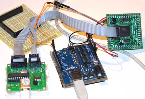
Then I wrote a quick sketch to simply read characters from USART0 and echo them back to the PC:

void setup()
{
Serial.begin(38400);
}

void loop()
{
while (Serial.available()) {
int c = Serial.read();
Serial.write(c);
}

To instead test the 2nd USART, substitute RXD1 for RXD0, TXD1 for TXD0, and Serial1 for Serial.

After burning the sketch, I simply opened the Arduino Serial Monitor, and typed characters to test the connection.  Much to my chagrin, the AT90CAN128 was echoing garbage back to the host.  I spent hours trying various things, checking and rechecking my wiring, to no avail.  I started to suspect that maybe the at90can files I got from SuperCow were inproperly configured.  One thing that raised this suspicion is that I found that the delay() function was running much slower than it should.  User evnow of the MyNissanLeaf forum pointed me to a HEX file of a similar serial echo program that Olimex posted on their site for the AVR-CAN board.  I burned the file into the AT90CAN128 using avrdude:

avrdude -c usbtiny -p at90can128 -U flash:w:avr-can_UART.hex

Once again, the board was corrupting the serial data.  This test showed that the culprit probably wasn’t SuperCow’s at90can files, since this hex file has been tested and working by other users.

Finally, it dawned on me that perhaps the fuses weren’t properly programmed.  I got a crash course on fuses from Adafruit’s avrdude tutorial.  Adfruit’s tutorial also linked to a great AVR fuse calculator.  First, I read out the fuses to 3 files:

avrdude -c usbtiny -p at90can128 -U lfuse:r:lfuse:h
avrdude -c usbtiny -p at90can128 -U hfuse:r:hfuse:h
avrdude -c usbtiny -p at90can128 -U efuse:r:efuse:h

The 3 commands above read the low, high, and extended fuses respectively, and output them as text files lfuse, hfuse, and efuse.  I found that the values were lfuse=0x4f, hfuse=0x19, efuse=0xff.  Using the Embedded Atmel AVR Fuse Calculator, I noticed that when lfuse=0x4f, that CKDIV8 (Clock divide by 8)  is enabled.  This didn’t seem right, and might account for the fact that the delay() function seemed to be running about 8x too slow.  Not knowing much about fuses, I decided to just use the value that Arduino uses for the ATmega328P, lfuse=0xFF, which turns off CKDIV8.

avrdude -c usbtiny -p at90can128 -U lfuse:w:0xFF:m

Bingo!  No more corrupted serial data, and the delay() function now runs at normal speed.  I have a feeling I’ll have to play with the other fuse bits at a later date, but since the board is working OK I’ll leave them be for now.  If you want to copy all of my current fuse settings, use this command:

avrdude -c usbtiny -p at90can128 -U lfuse:w:0xFF:m -Uhfuse:w:0x1F:m -U efuse:w:0xFF:m

Previous:  AVR CAN Bus Project – Step 1: Programming AT90CAN128 with Arduino
Next: AVR CAN Bus Project – Status Update 1
AVR CAN Bus Project – Step 1: Programming AT90CAN128 with Arduino

Last month, I bought a Nissan Leaf EV.  It’s pretty cool driving around in an all-electric car.  Luckily, there’s a great forum called MyNissanLeaf, where Leaf owners can learn a lot, and share information.  I’m currently collaborating with one of the forum members to design and build a Level 2 EVSE.  I will document that project on this blog at a later date.  Having a serious case of project ADHD, I discovered that forum members had set about hacking the Leaf’s CAN buses, and couldn’t resist joining the fray.

Being most familiar with ATmel AVR microcontrollers and Arduino, I decided to use that platform for this project.  ATmel has a subtype of the AVR with CAN bus capabilities, the AT90CANxxx.  I found an interesting development board containing an AT90CAN128 and headers for access to all the pins on the MCU.  I ordered one from Sparkfun for $29.95.  They also sell another board, the AVR-CAN, but it contains things that I don’t need, such as an RS-232 interface, and can be programmed only via JTAG – I only have a USBtinyISP, which is an ICSP programmer.  Unlike the AVR-CAN, the AT90CAN128 Header Board doesn’t contain a CAN Bus transceiver.  I decided to go with the Microchip MCP2551, since that’s what the AVR-CAN uses.

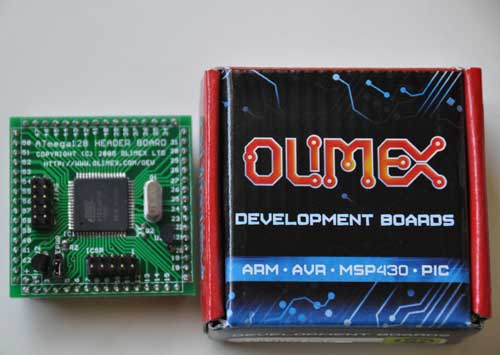
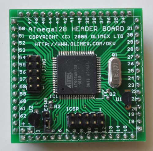
The AT90CAN128 header board is from Olimex, and comes in a cute little box:

Here’s a closeup of the front:

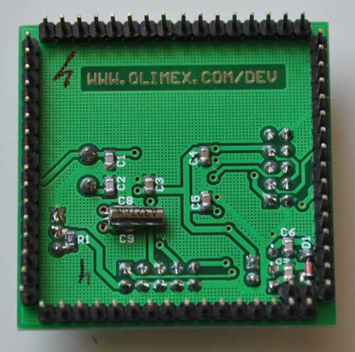
and the back:

I decided to try to get this board working with Arduino, since it’s a lot easier to set up than WinAVR.  The first problem to solve is how to adapt the Arduino IDE to work with the AT90CAN128 and my USBtinyISP.  After much Googling, I found SuperCow had already done the dirty work and posted it to the Arduino forum.  He packaged the core files, bootloader, and a couple of examples into a handy zip file (which has since been taken offline). Since he used an unknown JTAG programmer, I had to adapt his files to work with the USBtinyISP and JTAG ICE mk1.  Also, I modified them to work with Arduino 1.x+.

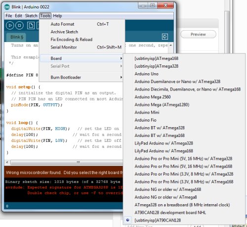
You can download the latest version from github: https://github.com/lincomatic/AT90CAN  To install it, simply unzip the atcan90 directory into <your arduino directory>/hardware/at90can.  Next time you restart Arduino, you can select it from Tools->Board->[usbtinyisp]AT90CAN128.

If you have a JTAG ICE mk1 programmer instead, select [JTAG ICE mk1]AT90CAN128.

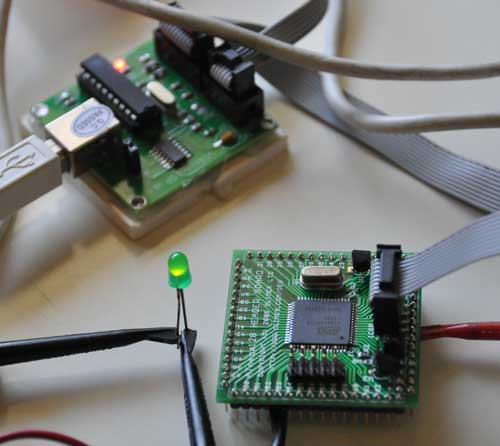
I connected up my USBtinyISP via the 10-pin ICSP header, burned the Blink sketch, hooked up an LED, and bingo!  It’s working flawlessly.

In at90can/cores/at90can, I found can_lib.h and can_lib.cpp, which appear to be all we need to interface to the CAN bus.  Since I currently know ZERO about CAN bus, I have a lot of reading to do before I can commence programming.  SuperCow’s original zip file contains a couple of rudimentary examples.

Before I start programming, I need to build a little interface board containing the MCP2551 CAN bus transceiver, which should arrive next week.  I already have an OBD-II cable to tap into the Leaf CAN bus via the OBD-II connector.  Currently, obdcables.com is having a special on the 9-ft model.


Downloads:  https://github.com/lincomatic/AT90CAN

Next: AVR CAN Bus Project – Step 2: Programming Low Fuse


Restoring AddressBook.sqlitedb to iPhone – A Simplified Procedure

In my previous article, I described how to restore contacts from a backup to an iPhone.  The infuriating thing about restoring AddressBook.sqlitedb to an iPhone is that one can’t just drop in a replacement file, because after you reboot, the new file gets overwritten with an empty one.  I traced the overwriting of the addressbook to a process called dataaccessd.  This process can’t be killed easily, because launchd will automatically restart it if it dies.  After some testing, I have now devised a procedure which is simpler than the one described in my previous article:

This procedure assumes that you have already obtained a copy of AddressBook.sqlitedb which contains the contacts you want to restore.

1. Using iFunBox, navigate to Raw File System/Library/LaunchDaemons and copy com.apple.AddressBook.plist and com.apple.dataaccess.dataaccessd.plist to your computer.

2. Using iFunBox, delete com.apple.AddressBook.plist and com.apple.dataaccess.dataaccessd.plist from your iPhone.

3. Power off and restart your iPhone

4. Using iFunBox, copy your AddressBook.sqlitedb into the iPhone at Raw File System/var/mobile/Library/AddressBook

5. Using iFunBox, copy the com.apple.AddressBook.plist and com.apple.dataaccess.dataaccessd.plist from your computer back to the Raw File System/Library/LaunchDaemons folder in your iPhone.

6. Power off and restart the iPhone, and enjoy your restored contacts.


Related articles:

How to Restore Lost Contacts to Your iPhone