AVR CAN Bus Project – Status Update 1

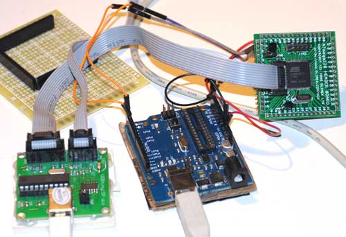
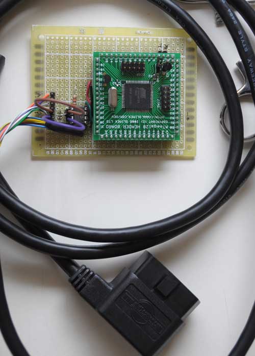
I got the circuit wired up yesterday:

The 6-pin jumper on the left lets me select one of the 3 CAN buses on the Nissan Leaf accessible via the OBD-II connector.

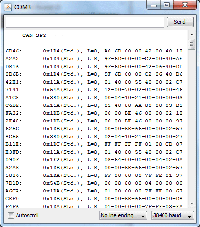
I hacked up some code quickly, and was pleasantly surprised that it actually worked! Woohoo! The part I thought was going to be most difficult – getting the CAN interface firmware working – turned out to be the easiest. Here’s my first capture of live data from the EV CAN bus:

Schematic and source code will follow.

Previous: AVR CAN Bus Project – Step 2: Programming Low Fuse
Next: AVR CAN Bus Project – Step 3: CANSpy CAN Bus Monitor

AVR CAN Bus Project – Step 2: Programming Low Fuse

One of the basic functions that the CAN Bus project needs is to be able to communicate with a PC via a serial port.  For modern PC’s the most straightforward way is to connect the AT90CAN128 header board to the host via a Serial->USB converter.  The most common type is the ubiquitous FTDI Cable, which is a USB cable with an embedded FT232R chip inside. Since I have a couple of spare Arduinos, I like to just use the embedded FT232R in the Arduino, rather than investing in a FTDI cable.  To use an Arduino as a serial cable, simply remove the ATmega328P MCU, and then connect the the TxD, RxD, and GND pins between the Arduino and the external device.

The AT90CAN128 has two USART’s.  The first one, on pins RXD0(2) and TXD0(3), is accessed via the Serial object in Arduino.  The second one, on pins RXD1(27) and TXD1(28), is accessed via the Serial1 object in Arduino.

To test serial communications with the host PC, I connected the first USART to the Arduino board with MCU removed as follows:

AT90CAN128 RXD0 pin 2 -> Arduino Digital 0 (RX)
AT90CAN128 TXD0 pin 3 -> Arduino Digital 1 (TX)
AT90CAN128 GND pin 53 -> Arduino GND

Then I wrote a quick sketch to simply read characters from USART0 and echo them back to the PC:

void setup()
{
Serial.begin(38400);
}

void loop()
{
while (Serial.available()) {
int c = Serial.read();
Serial.write(c);
}

To instead test the 2nd USART, substitute RXD1 for RXD0, TXD1 for TXD0, and Serial1 for Serial.

After burning the sketch, I simply opened the Arduino Serial Monitor, and typed characters to test the connection.  Much to my chagrin, the AT90CAN128 was echoing garbage back to the host.  I spent hours trying various things, checking and rechecking my wiring, to no avail.  I started to suspect that maybe the at90can files I got from SuperCow were inproperly configured.  One thing that raised this suspicion is that I found that the delay() function was running much slower than it should.  User evnow of the MyNissanLeaf forum pointed me to a HEX file of a similar serial echo program that Olimex posted on their site for the AVR-CAN board.  I burned the file into the AT90CAN128 using avrdude:

avrdude -c usbtiny -p at90can128 -U flash:w:avr-can_UART.hex

Once again, the board was corrupting the serial data.  This test showed that the culprit probably wasn’t SuperCow’s at90can files, since this hex file has been tested and working by other users.

Finally, it dawned on me that perhaps the fuses weren’t properly programmed.  I got a crash course on fuses from Adafruit’s avrdude tutorial.  Adfruit’s tutorial also linked to a great AVR fuse calculator.  First, I read out the fuses to 3 files:

avrdude -c usbtiny -p at90can128 -U lfuse:r:lfuse:h
avrdude -c usbtiny -p at90can128 -U hfuse:r:hfuse:h
avrdude -c usbtiny -p at90can128 -U efuse:r:efuse:h

The 3 commands above read the low, high, and extended fuses respectively, and output them as text files lfuse, hfuse, and efuse.  I found that the values were lfuse=0x4f, hfuse=0x19, efuse=0xff.  Using the Embedded Atmel AVR Fuse Calculator, I noticed that when lfuse=0x4f, that CKDIV8 (Clock divide by 8)  is enabled.  This didn’t seem right, and might account for the fact that the delay() function seemed to be running about 8x too slow.  Not knowing much about fuses, I decided to just use the value that Arduino uses for the ATmega328P, lfuse=0xFF, which turns off CKDIV8.

avrdude -c usbtiny -p at90can128 -U lfuse:w:0xFF:m

Bingo!  No more corrupted serial data, and the delay() function now runs at normal speed.  I have a feeling I’ll have to play with the other fuse bits at a later date, but since the board is working OK I’ll leave them be for now.  If you want to copy all of my current fuse settings, use this command:

avrdude -c usbtiny -p at90can128 -U lfuse:w:0xFF:m -Uhfuse:w:0x1F:m -U efuse:w:0xFF:m

Previous:  AVR CAN Bus Project – Step 1: Programming AT90CAN128 with Arduino
Next: AVR CAN Bus Project – Status Update 1

AVR CAN Bus Project – Step 1: Programming AT90CAN128 with Arduino

Last month, I bought a Nissan Leaf EV.  It’s pretty cool driving around in an all-electric car.  Luckily, there’s a great forum called MyNissanLeaf, where Leaf owners can learn a lot, and share information.  I’m currently collaborating with one of the forum members to design and build a Level 2 EVSE.  I will document that project on this blog at a later date.  Having a serious case of project ADHD, I discovered that forum members had set about hacking the Leaf’s CAN buses, and couldn’t resist joining the fray.

Being most familiar with ATmel AVR microcontrollers and Arduino, I decided to use that platform for this project.  ATmel has a subtype of the AVR with CAN bus capabilities, the AT90CANxxx.  I found an interesting development board containing an AT90CAN128 and headers for access to all the pins on the MCU.  I ordered one from Sparkfun for $29.95.  They also sell another board, the AVR-CAN, but it contains things that I don’t need, such as an RS-232 interface, and can be programmed only via JTAG – I only have a USBtinyISP, which is an ICSP programmer.  Unlike the AVR-CAN, the AT90CAN128 Header Board doesn’t contain a CAN Bus transceiver.  I decided to go with the Microchip MCP2551, since that’s what the AVR-CAN uses.

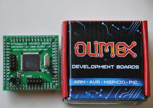
The AT90CAN128 header board is from Olimex, and comes in a cute little box:

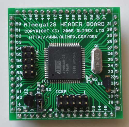
Here’s a closeup of the front:

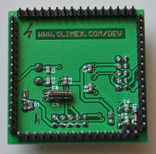
and the back:

I decided to try to get this board working with Arduino, since it’s a lot easier to set up than WinAVR.  The first problem to solve is how to adapt the Arduino IDE to work with the AT90CAN128 and my USBtinyISP.  After much Googling, I found SuperCow had already done the dirty work and posted it to the Arduino forum.  He packaged the core files, bootloader, and a couple of examples into a handy zip file (which has since been taken offline). Since he used an unknown JTAG programmer, I had to adapt his files to work with the USBtinyISP and JTAG ICE mk1.  Also, I modified them to work with Arduino 1.x+.

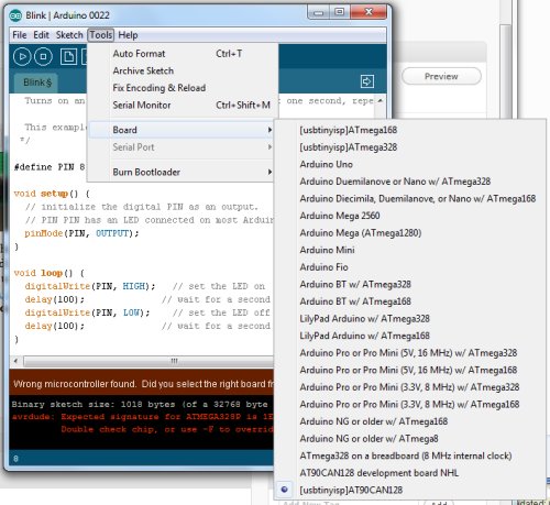
You can download the latest version from github: https://github.com/lincomatic/AT90CAN  To install it, simply unzip the atcan90 directory into <your arduino directory>/hardware/at90can.  Next time you restart Arduino, you can select it from Tools->Board->[usbtinyisp]AT90CAN128.

If you have a JTAG ICE mk1 programmer instead, select [JTAG ICE mk1]AT90CAN128.

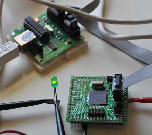
I connected up my USBtinyISP via the 10-pin ICSP header, burned the Blink sketch, hooked up an LED, and bingo!  It’s working flawlessly.

In at90can/cores/at90can, I found can_lib.h and can_lib.cpp, which appear to be all we need to interface to the CAN bus.  Since I currently know ZERO about CAN bus, I have a lot of reading to do before I can commence programming.  SuperCow’s original zip file contains a couple of rudimentary examples.

Before I start programming, I need to build a little interface board containing the MCP2551 CAN bus transceiver, which should arrive next week.  I already have an OBD-II cable to tap into the Leaf CAN bus via the OBD-II connector.  Currently, obdcables.com is having a special on the 9-ft model.


Downloads:  https://github.com/lincomatic/AT90CAN

Next: AVR CAN Bus Project – Step 2: Programming Low Fuse


Arduino-lite – A Lightweight Runtime for AVR

I just ran across Arduino-lite, a lightweight alternative runtime to Arduino, for programming AVR MCU’s.  This project is spearheaded by Robopeak Project.  It looks pretty cool.  It’s kind of halfway between Arduino, and coding directly with avr-gcc.  It supports the standard Arduinos, as well as:

  • Atmega8(A)
  • Atmega168(PA)
  • Atmega328(PA)
  • Atmega1280
  • Attiny2313
  • Attiny26
  • Atmega48(PA)
  • Atmega88(PA)

Not only does it support more MCU’s than Arduino, it also supports frequencies from 1-20MHz, unlike Arduino, which only supports 8 & 16MHz.

Furthermore, Robopeak claims that Arduino-lite’s binaries are 50% smaller than those produced by Arduino. An example on Robopeak’s Blog shows how Arduino-lite reduces the digitalWrite() function down to 1 AVR instruction.  It appears to make heavy use of macros, which is nice, because it eliminates function call overhead.  On the other hand, type checking and such is severely restricted.  I think it might be a great tool for projects that need to be compact, or run as fast as possible.  Also, it will greatly simplify coding for the ATtiny MCU’s.

It’s definitely not for n00bs, but if you’re comfortable with makefiles, give it a shot.  The download includes everything you need to get started.  You can download it for free from google code.

I just downloaded it, and am going to give it a whirl.  It almost sounds too good to be true.  If you have any experience with it, please leave a comment.

Download Arduino-lite: http://code.google.com/p/arduino-lite/

Lampduino – an 8×8 RGB Matrix Floor Lamp

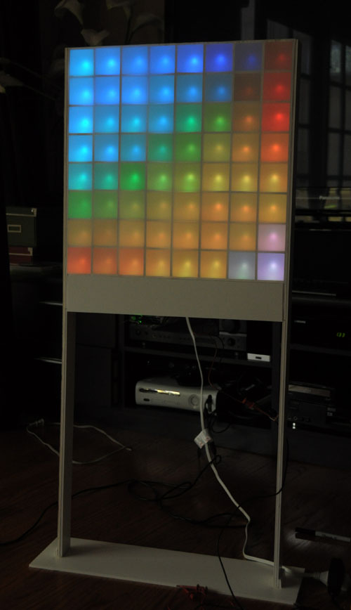
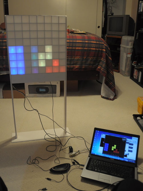
This past weekend, I finally finished building my 8×8 RGB matrix floor lamp.  I call it Lampduino.  A Processing sketch running on a host computer controls Lampduino via a USB connection.  When turned on without a computer, it automatically displays a soothing plasma simulation. If you want to build one of your own, I wrote a step by step Instructable:

Lampduino – an 8×8 RGB Matrix Floor Lamp


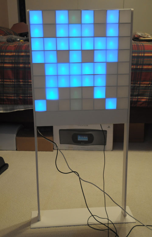
Space Invaders

Tetris

Related articles:

Colorduino Library for Arduino

I wrote a Colorduino library for Arduino.  It handles initialization and double-buffered drawing on ITead Studio’s Colorduino.  It is also compatible with Itead’s Arduino RGB Matrix driver shield. Included with the library is a sample sketch to show how to use it, ColorduinoPlasma, which draws a pretty plasma on an 8×8 RGB matrix.

To install the library, download the zip file (see below), and copy libraries/Colorduino to your arduino sketchbook/libraries/Colorduino. If you are already running the Arduino IDE, you must restart it before you can use the library. You can then run load ColorduinoPlasma.pde demo.

To include the Colorduino library in your own sketch, just

#include <Colorduino.h>

Then your setup() function needs to just call two functions for initialization:

void setup()
{
Colorduino.Init();
// compensate for relative intensity differences in R/G/B brightness
// array of 6-bit base values for RGB (0~63)
// whiteBalVal[0]=red
// whiteBalVal[1]=green
// whiteBalVal[2]=blue
unsigned char whiteBalVal[3] = {36,63,63}; // for LEDSEE 6x6cm round matrix
Colorduino.SetWhiteBal(whiteBalVal);
}

Colorduino.SetWhiteBal() is used to adjust the white balance. You can put

ColorFill(255,255,255);

in your sketch to test the white balance by drawing a white screen.  Then adjust whiteBalVal until your screen approximates white.

The origin of the screen, (0,0) is at the bottom left corner. The off screen buffer can be accessed either pixel by pixel:

Colorduino.SetPixel(x,y,r,g,b);

or by direct manipulation.  The screen buffer is arranged by row. For instance to set all of the pixels in the second row to the same color:

PixelRGB *p = GetPixel(0,1);
for (int x=0;x < ColorduinoScreenWidth;x++) {
p->r = red;
p->g = green;
p->b = blue;
p++;
}

After you finish updating your screen, make it live by swapping it with the currently display buffer:

Colorduino.FlipPage();

The latest version of the Colorduino library can always be downloaded from github: https://github.com/lincomatic/Colorduino/archive/master.zip

ITead Studio Colorduino – A Preview

ITead Studio kindly sent me a Colorduino for beta testing. The Colorduino was inspired by SeeedStudio’s Rainbowduino LED Driver Platform. Its form factor is very similar to that of the Rainbowduino, and the layout of the connectors was intentionally designed to mimic the latter. Both boards are based on the ATmega368 MCU, and are Arduino compatible. The principal difference between the platforms is that while the Rainbowduino is based on 3 MBI5168 constant current sink drivers and a M54564 darlington source driver, the Colorduino pairs the M54564 with a single DM163 constant current driver. By using the DM163, the Colorduino gains three 8+6-bit channels of hardware PWM control of the LED’s freeing up the MCU from having to implement it in software. This gives the ATmega more CPU bandwidth for performing other tasks. In contrast, the Rainbowduino implements three 4-bit channels of software PWM. One important limitation, however, is that the DM163 only has 24 channels… this is just enough to buffer one line of 8 RGB LED’s (8×3 = 24), rather than an entire 8×8 RGB matrix. So while the MCU is freed of the software PWM task, it still has to constantly scan line by line to refresh the screen. However, the row scanning takes up considerably less CPU bandwidth than having to also handle software PWM, and ups the bit resolution of each color channel to 8+6 bits.

The extra 6 bits of data in each color channel allows software control of the relative PWM brightness, so that the user may not have to resort to using external resistors to adjust relative channel current (which is also supported by the DM163, but the Colorduino, unlike the Rainbowduino, does not have onboard potentiometers for adjusting individual RGB current).   The Colorduino is quite compact (the same size as the Rainbowduino), being slightly smaller than the 60x60mm common anode RGB LED for which it is designed as a direct plug-in.

The Colorduino is pictured below:
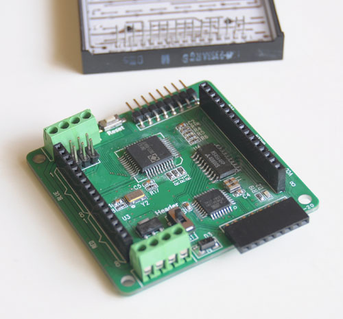
Behind the Colorduino is my LEDSEE 60x60mm RGB matrix.

Below is a top view:

Keep in mind that this is a beta board, and ITead is still tweaking it.  One problem I found is that the ICSP header doesn’t have enough clearance for me to plug in my USBtinyISP.  The sliding switch is for selecting betwen onboard regulator (for use with 7-12V power supplies) or a regulated 5V input.  As you can see, the board is a bit rough looking, with crooked parts and flux residue.  ITead Studio has assured me that the ICSP header will be moved to a better location, and that the production boards will be cleaner.  Also, although the beta boards have an ATmega168, the production boards will use the ATmega368.  Note the 8-pin headers for easy daisy chaining.  When multiple boards are snapped together, a host can address each one individually via I2C.  The power is also easily interconnected between the boards via the dual 4-pin green screw terminals.  Bottom view below, snapped into the 8×8 RGB matrix:

From the photo above, you can see how compactness of the Colorduino.   It’s slightly smaller than the RGB matrix.  NOTE: The bypass cap yellow added between VDD and GND will be moved to the PCB before production.  One downside of the Colorduino (which is shared by the Rainbowduino), is the dearth of I/O pins left over for the user.  TX/RX/SCL/SDA are all you have to play with, and some or all of them may needed for communication.  If you need more I/O, a likely scenario will be to connect the Colorduino to an Arduino via I2C.  Kind of a shame, given that the hardware PWM frees up considerable CPU bandwidth for other functions.

Below is the Colorduino running a plasma demo.  Notice my Arduino Duemilanove attached on the left, supplying power.  Since I can’t use ICSP, I’m using the Duemilanove, which you can see on the left, as a serial programmer.  I would like to get my USBtinyISP connected, so I regain some of the ATmega168’s small memory space by getting rid of the bootloader.
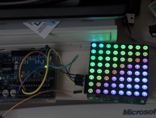
Finally, below is a rather horrible video of it running ITead’s demo code, followed by my plasma demo.  There is absolutely no flicker when viewed with the naked eye, what you see in the video is just an artifact.


The photos and video don’t do it justice.  The Colorduino supplies considerable drive current, making the matrix blindingly bright.  The LEDSEE 8×8 matrix is gorgeous.  I wish I could capture it properly in my photos.  I chose it because it was cheaper than the alternatives I found, while having the brightest output.  However, it took 2 weeks for LEDSEE to ship it out, and in total, it took over a month for me to receive it.  I sent them several inquiries about my order, which they completely ignored.   In light of their bad (nonexistent) customer service, I doubt I will deal with LEDSEE again.  ITead, on the other hand, has been quite responsive in their communications.

Currently, the Colorduino documentation is rather sparse.  ITead has a blog entry where you can download the schematic, DM163 spec, and their sample Arduino sketch.  ITead anticipates that the revisions will be completed and it will be put into their iStore sometime in April.  They are targeting a price of about $27, slightly higher than the Rainbowduino.  ITead Studio also makes an
Arduino RGB LED Matrix driver shield, which is already available for $14.80. When this shield is plugged into an Arduino Uno/Duemilanove, the combination is equivalent to a Colorduino, and uses exactly the same code.

Upon initial testing, the Colorduino appears to be a worthy challenger to the more established Rainbowduino, which has already spawned a dedicated ecosystem of  hackers, as well as a wiki full of detailed information. While the Colorduino has a lot of catching up to do, it seems quite capable, I look forward to running it through its paces in the coming weeks, when I use it to implement a large scale 8×8 RGB matrix.

You can download my plasma sketch, along with my interface library here: Colorduino Library for Arduino
How to Use the Arduino IDE with an External Programmer

If you have a hardware AVR programmer, such as the USBtinyISP, you can configure your Arduino IDE to use it for uploading sketches, rather than the standard USB interface.  Why would you want to do this?

  1. it uploads faster
  2. your project will boot faster
  3. you can load bigger sketches, because you don’t need the bootloader anymore.
  4. it’s a lot more convenient when debugging communications between a host computer and the Arduino’s serial port, because you don’t have to share the port with the Arduino IDE and take turns accessing it.
  5. you want to build a project which uses the Rx/Tx pins on the MCU, which conflicts with programming via serial.
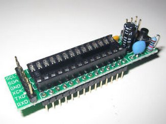
  6. you can use it to program stripped down AVR boards, such as the $2.99 board pictured below:


Windows users only: First, you must install the device driver. Follow the instructions here: http://www.ladyada.net/make/usbtinyisp/drivers.html


First, open your Arduino/hardware/arduino/boards.txt file in a text editor, and add the following lines:

##############################################################

usbtiny328.name=[usbtinyisp]ATmega328

usbtiny328.upload.using=usbtinyisp
usbtiny328.upload.maximum_size=32768

usbtiny328.build.mcu=atmega328p
usbtiny328.build.f_cpu=16000000L
usbtiny328.build.core=arduino
usbtiny328.build.variant=standard

Note:  The …variant=standard line is only needed for Arduino 1.0+. Older versions of Arduino will just ignore it.

If you’re using a programmer other than a USBtinyISP, substitute its identifier where I’ve typed usbtinyisp above. You can see the options in your hardware/arduino/programmers.txt file. In arduino-0022, the options are avrisp, avrispmkii, usbtinyisp, and parallel (beware, it’s case sensitive, so for instance, you must type usbtinyisp, not USBtinyISP). To support a different MCU, substitute it in the usbtiny328.build.mcu= line, e.g. atmega168. If you want to support more than one programmer/MCU combination, just add multiple sections with the different configurations to your boards.txt file.

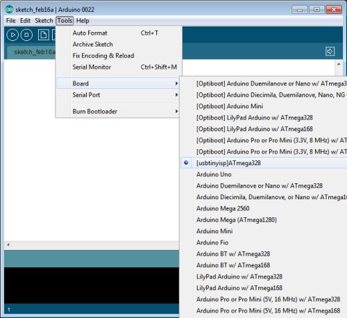
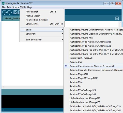
Next, hook up your programmer to the ICSP header on your board, and plug it into your computer. Select your new board configuration from the arduino Tools->Board menu:

Now, you can burn your sketch as usual, via the Upload button. Note that your bootloader will be overwritten, so you won’t be able to burn sketches to the same board without your programmer, unless you follow my instructions for restoring the bootloader below. On the other hand, after configuring your arduino software as described above, you can still burn sketches to arduinos which have the bootloader installed without your programmer. Simply pick the correct board from the Tools->Board menu.

———————————————————
Restoring the Bootloader

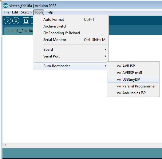
Once you’ve burned a sketch to an arduino via ICSP, the bootloader will be overwritten. If you want to revert to burning your sketch without a programmer, you must first restore the bootloader. With your programmer connected via ICSP, select Tools->Burn Bootloader:

Now, you can disconnect your programmer and hook your arduino directly to the computer via USB. From the Tools->Board menu, select your board:

Now, things are back to normal, and you can burn your sketch via the Upload button.

Build Your Own Daft Punk Table (5×5 LED Display)

Welcome my blog. This is my first post.

This is a 5×5 LED matrix display I built, using an ATmega368 microcontroller (arduino) and 25 warm white LED’s.  It was inspired by the Daft Punk coffee table, which is no longer sold.

I posted my first Instructable last Sunday.  It got selected by the editors to be Featured, which won me a free 3-month Pro membership.  I entered it into the Sparkfun Microcontroller Contest.  Today is the last day of voting.

http://www.instructables.com/id/Yet-Another-Daft-Punk-Coffee-TableDisplay/

I will be revising it and adding features, such as live music synchronization. I will post the developments on this blog as they happen, with detailed instructions.