My BAITE BTE14-07 Maple Mini clone came with LeafLabs’ original bootloader. I decided to upgrade to Bootloader 2.0 in order to free up some RAM, and take advantage of some of the new features.
UPDATE: Roger Clark, the STM32DUINO guru, posted a comment below, informing me that you can upload to Bootloader 2.0 by simply loading the updater sketch, without a USB->UART adapter, so you can try that first, and save my procedure below for if it somehow fails and bricks your Maple Mini.
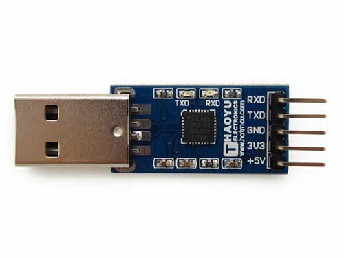
The procedure looks pretty straightforward, but I ran into some snags. Perhaps the easiest way to change the bootloader in a Maple Mini is to use the STM32’s built-in serial bootloader to flash it in. The serial bootloader is in ROM, so it’s a fail-safe method to program the chip. The technique involves hooking up UART1 to a USB->UART adapter. I had a spare CP2101-based adapter that works with 3.3V hardware:
The hookup is straightforward:
TX -> rx1
RX -> tx1
3V3 -> Vcc
GND -> GND
BOOT1 ->GND
Here is what it looks looks like all hooked up:
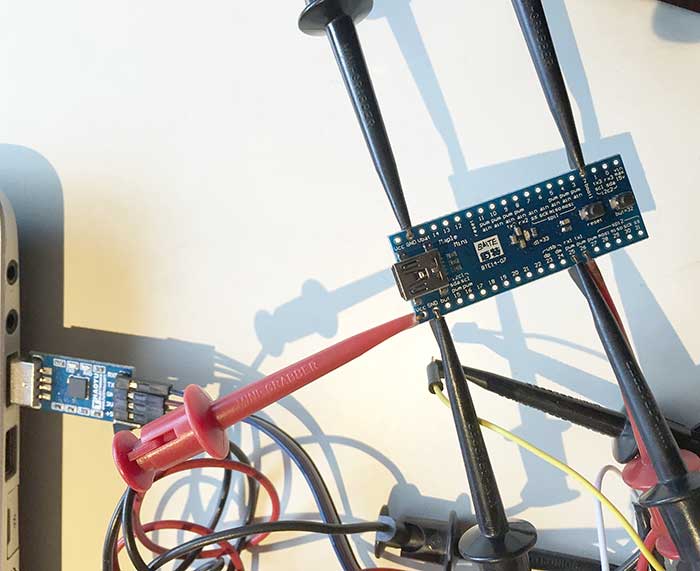
Actually the RX1 & TX1 pins are 5V tolerant, so you can even use a 5V USB->UART adapter. Just make sure to hook up 5V -> vin instead of to Vcc, or you’ll be in for a very unpleasant surprise.
There are several programs available that can program the STM32 in serial bootloader mode. I tried both stm32load.py and stm32flash. Also, you will need the binary bootloader file, maple_mini_boot20.bin.
To put the board into serial bootloader mode, press and hold reset and but, release reset, and then release but. The board will look dead. This is normal. Then execute the command to flash in the bootloader. stm32flash is more straightforward, because it doesn’t require you to install Python. There are pre-compiled versions of stm32flash for various platforms in Arduino_STM32’s tools directory. My computer runs Windows 8.1, so I used the stm32flash.exe:
C:\git\Arduino_STM32\tools\win>stm32flash -w maple_mini_boot20.bin COM19 -b 230400 -g 0
stm32flash 0.4
http://stm32flash.googlecode.com/
Using Parser : Raw BINARY
Interface serial_w32: 230400 8E1
Version : 0x22
Option 1 : 0x00
Option 2 : 0x00
Device ID : 0x0410 (Medium-density)
– RAM : 20KiB (512b reserved by bootloader)
– Flash : 128KiB (sector size: 4×1024)
– Option RAM : 16b
– System RAM : 2KiB
Write to memory
Erasing memory
Wrote address 0x08001b7c (100.00%) Done.
Note that you need to substitute your USB->UART converter’s serial port for COM19.
If you prefer Python, you can use stm32load.py instead. Make sure to use the version from the Arduino_STM32/tools directory. I tried to use the version from STM32duino-bootloader and the version from libmaple, and both of them wrote only the first 512 bytes of the bootloader, so the Maple Mini was no longer detected at all when plugged into my computer.
Here is how to execute stm32loader.py:
C:\git\Arduino_STM32\tools\win>stm32loader.py -p COM19 -evw \hacking\STM32\maple_mini_boot20.bin
Reading data from \hacking\STM32\maple_mini_boot20.bin
Bootloader version 0x22
Chip id 0x410, STM32F1, performance, medium-density
Writing 7036 bytes to start address 0x8000000
Write 256 bytes at 0x8000000
Write 256 bytes at 0x8000100
Write 256 bytes at 0x8000200
Write 256 bytes at 0x8000300
Write 256 bytes at 0x8000400
Write 256 bytes at 0x8000500
Write 256 bytes at 0x8000600
Write 256 bytes at 0x8000700
Write 256 bytes at 0x8000800
Write 256 bytes at 0x8000900
Write 256 bytes at 0x8000A00
Write 256 bytes at 0x8000B00
Write 256 bytes at 0x8000C00
Write 256 bytes at 0x8000D00
Write 256 bytes at 0x8000E00
Write 256 bytes at 0x8000F00
Write 256 bytes at 0x8001000
Write 256 bytes at 0x8001100
Write 256 bytes at 0x8001200
Write 256 bytes at 0x8001300
Write 256 bytes at 0x8001400
Write 256 bytes at 0x8001500
Write 256 bytes at 0x8001600
Write 256 bytes at 0x8001700
Write 256 bytes at 0x8001800
Write 256 bytes at 0x8001900
Write 256 bytes at 0x8001A00
Write 256 bytes at 0x8001B00
Read 256 bytes at 0x8000000
Read 256 bytes at 0x8000100
Read 256 bytes at 0x8000200
Read 256 bytes at 0x8000300
Read 256 bytes at 0x8000400
Read 256 bytes at 0x8000500
Read 256 bytes at 0x8000600
Read 256 bytes at 0x8000700
Read 256 bytes at 0x8000800
Read 256 bytes at 0x8000900
Read 256 bytes at 0x8000A00
Read 256 bytes at 0x8000B00
Read 256 bytes at 0x8000C00
Read 256 bytes at 0x8000D00
Read 256 bytes at 0x8000E00
Read 256 bytes at 0x8000F00
Read 256 bytes at 0x8001000
Read 256 bytes at 0x8001100
Read 256 bytes at 0x8001200
Read 256 bytes at 0x8001300
Read 256 bytes at 0x8001400
Read 256 bytes at 0x8001500
Read 256 bytes at 0x8001600
Read 256 bytes at 0x8001700
Read 256 bytes at 0x8001800
Read 256 bytes at 0x8001900
Read 256 bytes at 0x8001A00
Read 256 bytes at 0x8001B00
Verification OK
Traceback (most recent call last):
File “C:\git\Arduino_STM32\tools\win\stm32loader.py”, line 531, in
if conf[‘go’]:
KeyError: ‘go’
I don’t know what’s the cause of the error at the end, but as long as it writes 7036 bytes, you see Verification OK, the bootloader is installed correctly. Whe I ran the bad versions of stm32loader.py, here is what the output looked like:
Bootloader version 22
Chip id `[‘0x4’, ‘0x10′]’
Write 256 bytes at 0x8000000
Write 256 bytes at 0x8000100
Read 256 bytes at 0x8000000
Read 256 bytes at 0x8000100
Verification OK
Even though it showed Verification OK, note how only 512 bytes were written to the Maple Mini.
If you have successfully flashed in the bootloader, the LED will flash continuously after you reset the board, indicating that the bootloader is running. In Arduino, you also must switch the setting to from Original to Bootloader 2.0:
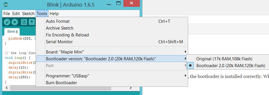
If, for some reason, you want to revert to LeafLabs’ original bootloader, you can download it here: maple_mini_boot.bin.
The built-in STM32 serial bootloader is not only for installing bootloaders. You can also use it to flash in any other BIN file, including Arduino_STM32 sketeches.