WS2812B LED (NeoPixel) Control: Part 2 – WiFi Control via Art-Net on ESP8266

INTRODUCTION

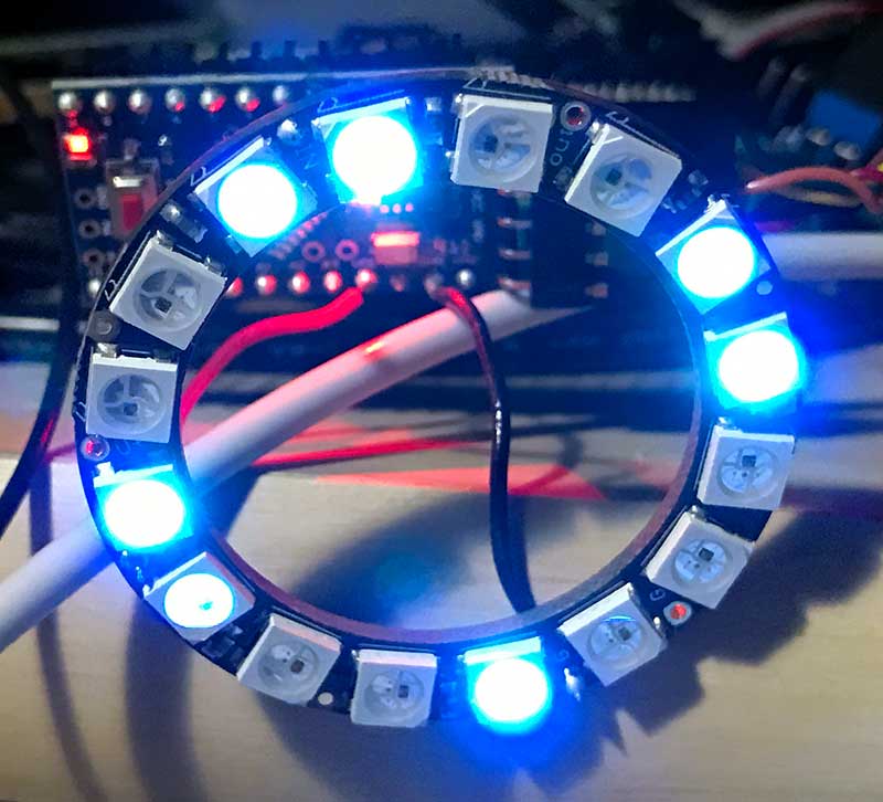
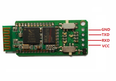
For wireless control of WS2812B (NeoPixel) LEDs, I initially played with Bluetooth SPP (Serial Port Profile), due to the simplicity of setting up the host software… from the host’s software’s point of view, the connection just looks like a physical serial port. Unfortunately, the flakiness of my Windows 8.1 PCs’ Bluetooth SPP support caused me to abandon that solution.

WIFI CONTROLLER HARDWARE

ESP8266 modules provide a very low cost method of interfacing WS2812Bs to WiFi. Adafruit’s Huzzah module costs $9.95, but on eBay, NodeMCU clones, such as the LoLin NodeMCU board can be had for ~$3 shipped from China. This makes it even cheaper than the Arduino/Bluetooth combination!

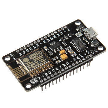
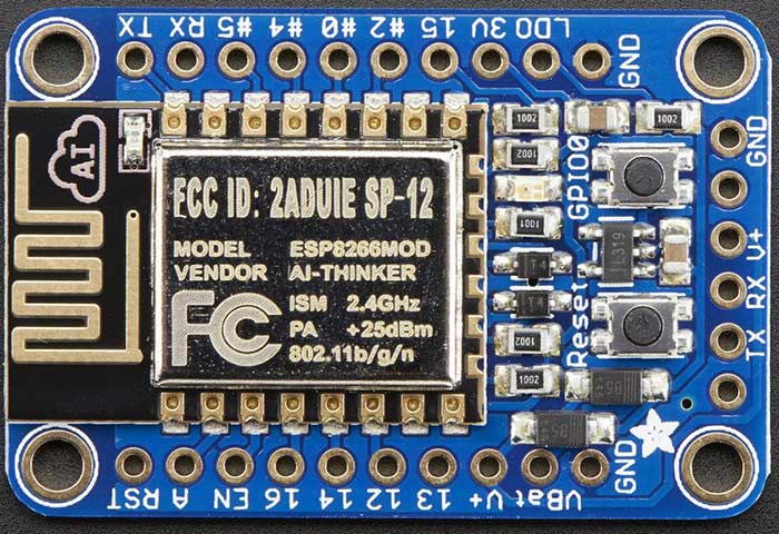
What’s more, the LoLin board has a CH340G onboard, so it doesn’t require a FTDI cable to connect it to your host computer for programming. I ordered a few of the LoLin boards, but in the meantime, I started playing with the Adafruit Huzzah boards I had on hand.

With the addition of ESP8266 support via the Board Manager, Arduino becomes an easy to use platform for code development. Also, there are easily obtainable libraries for both WiFi configuration and control of the WS2812Bs.

One extra complexity of using an ESP8266 to control WS2812Bs is that the ESP8266 is a 3.3V device, while the WS2812B is a 5V device, (usually) necessitating level shifting. The WS2812B datasheet shows a threshold of >= 0.7VDD for logic HIGH, and <= 0.3VDD for logic LOW. The allowed VDD ranges from +3.5-5.3V. Interestingly, some WS2812Bs can actually work when powered by 3.3V, and driven by 3.3V logic, even though it’s out of spec, but many cannot. On the other hand, it’s totally within spec to be powered by 3.7V and driven by 3.3V logic. So, if you use a 3.7V LiPo battery to power the WS2812B strand, the WS2812B data line can be connected directly to the ESP8266 without any level shifting! If you choose to go this route, power the Huzzah from its VBat terminal, so that the 3.7V will be regulated down to 3.3V to power the ESP8266. More details are available in Adafruit’s NeoPixel Uber Guide.

Since I want to be able to drive long strands of LEDs, I elected to go the 5V power with level shifter route. Also, I have lots of 5V power supplies laying around. There are many different ways to do level shifting, either passive or active. The WS2812B has tight timing requirements, and runs at 800KHz, so care has to be taken in order to avoid signal distortion. One of the most reliable methods is to use a 74AHCT125 level shifter IC. I decided to first try a simple diode and pullup resistor circuit (credit: RPi GPIO Interface Circuits):

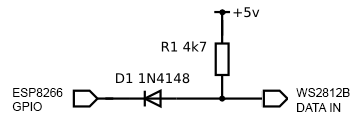
The circuit is currently working flawlessly for me, driving my 5m long strand of 150 LEDs.

WIFI COMMUNICATION PROTOCOL

In order to send data to our WS2812Bs over WiFi, we need some sort of IP protocol. Art-Net is a royalty-free protocol, which sends DMX data embedded in UDP packets. I decided to go with Art-Net because it is an industry standard that is supported by a variety of Pro software, and Jinx! and Glediator can talk to it.

ARDUINO FIRMWARE

I will not go into how to set up Arduino to compile sketches for the ESP8266, as that is discussed elsewhere. To compile for the Huzzah, select it as the compile target from the Tools pulldown menu:

Tools -> Board -> Adafruit HUZZAH ESP8266

I created a sketch, which is a mashup of a few different projects from github. The code is in my github repo: WS2812ArtNet. I stripped the Adafruit NeoPixel library down to the bare metal, and added a captive portal for configuring the WiFi connection. Also, it supports a hardware pin to erase the WiFi settings. Configuration is done via a few defines in WS2812ArtNet.ino. See the #defines for PIXEL_CNT, PIN_DATA, PIN_LED, and PIN_FACTORY_RESET. At a minimum, PIXEL_CNT must be set to the number of LEDs in your strand.

PIN_DATA is used to select the pin that’s used to drive the data to the LED strand.

PIN_LED is used to select the a pin which blinks an LED every time an Art-Net packet is received. This makes it easy to tell if the board is receiving data. In addition, the LED is initially off at boot-up, and turns solid red when the ESP8266 connects successfully to a WiFi AP. By default, PIN_LED = 0, which makes it control the onboard red LED on the Huzzah.

PIN_FACTORY_RESET wipes out any saved settings and clears the EEPROM when it’s grounded for 2 sec.

To load the WS2812ArtNet sketch into the ESP8266, first press the GPIO0 and Reset buttons simultaneously, and then let go of the Reset button. The red LED will then glow dimly, indicating that the bootloader is active. Once the sketch is loaded, when the ESP8266 initially boots up, it will create a WiFi AP with SSID WS2812ArtNet_hh-h. Use a computer, phone, etc to connect to the AP. Upon connection, it should automatically present a captive portal for configuration:

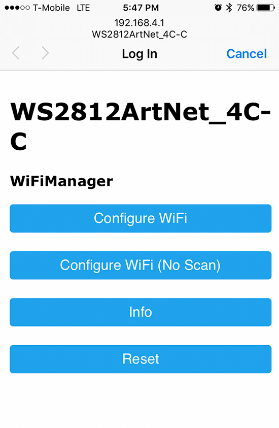
If the captive portal doesn’t automatically launch, open a web browser, and point it to http://192.168.4.1. Tap on Configure WiFi, and the ESP8266 will automatically scan for available APs:

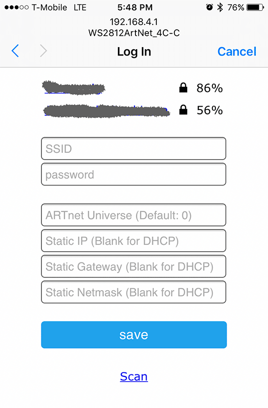
Tap the desired AP’s SSID, and type in the passphrase. Additionally, you can also choose a starting Art-Net universe, and configure a static IP. After you tap save, the ESP8266 will reboot. If it connects successfully to your AP, the onboard red LED will light. Then, the LED strand will go into the startup test sequence of lighting up red, green, and blue, and then turning off. Once Art-Net data is received, the LED still start blinking with every packet it receives.  If you have trouble during setup, you can see debug messages by opening the ESP8266’s serial port in a terminal set to 115200,N,8,1.


When configuring Jinx!/Glediator, select GRB as the pixel data format.


Prev: WS2812B LED (NeoPixel) Control: Part 1 – Serial Control via 8-bit ATmega (Arduino)

WS2812B LED (NeoPixel) Control: Part 1 – Serial Control via 8-bit ATmega (Arduino)

INTRODUCTION

I’ve been laying the groundwork for doing some projects using remote controlled RGB LEDs. My first attempt was Lampduino, which used discrete RGB LEDs, and an ITEAD Colorduino as a controller. In that project, I ran into several pitfalls:

  • though inexpensive, assembly of the LED matrix was very labor intensive
  • the LED’s were rather dim, due to the limited drive capability of the Colorduino
  • the frame rate was slow, due to limited baud rate and RAM
  • while it was scalable, I didn’t like the idea of having to use a separate Colorduino for every 64 LEDs

A few years have passed, and WS2812B LEDs have dropped enough in price enough to get into the range that I feel is affordable. They can be found on eBay and AliExpress very cheaply. Also, they can be controlled without any specialized hardware – all that is needed is one GPIO pin. There are libraries available for many of the popular microcontrollers. Some examples are Arduino, ESP8266, Teensy 3.x, and Raspberry Pi.

HOST SOFTWARE

The other piece of the puzzle is control software. For Lampduino, I hacked uRaNGaTaNG’s mtXcontrol Processing sketch into rgbMtx, but I found Processing to be a very limiting platform, which was hard to debug. This time around, I found a couple of interesting free LED control programs, which are both quite powerful. The first one is Jinx! LED Matrix Control, which runs on Windows only, and the second is Glediator, which is a Java app. Both programs, while free, are not open source. However, they are both powerful enough to do some interesting things.

HARDWARE

I decided to start my experiments with an Arduino Pro Mini clone, because they have a tiny footprint, are cheap (clones are <$2 shipped from China on eBay), and I happened to have some laying around. Also, the Arduino Pro Mini’s ATmega 328P MCU runs at 5V, so no level shifting is required when interfacing to WS2812Bs. Glediator’s creator, Solderlab, has barebones, fast serial client Arduino sketch which can be downloaded at: WS2812-Glediator-Interface. It can run on any 8-bit ATmega-based Arduino such as the Mega, UNO, Deumilanove, etc. The code that outputs the data to the LEDs is written in assembly language, and is thus, very fast & compact. Also, rather than using Arduino’s Serial library, it contains its own very compact serial code. At the expense of a little bit of speed, I decided to generalize it a bit, and add my own packet protocol. My code is on github at: WS2812Remote. The main changes that I made in my version of the code are:

  • Since I didn’t understand the Glediator example’s serial code, I reverted to using Arduino’s built-in Serial library. I’ve tested it with baud rates up to 1000000 and an FTDI cable on a Windows PC, and it works fine
  • I added support for my own packet protocol. Glediator’s serial protocol is extremely simple. Each frame starts with 0x01, followed by the pixel data stream. My simple packet protocol adds an XOR check byte, as well as a few simple commands such as color fill and blanking of the LEDs.

I also wrote a C++ program, called pkt_test, which demonstrates usage of my packet protocol.

Hookup of the WS2812B LED strand to the Arduino is quite simple. You can use any 8-bit Arduino. First, you must select a data pin to drive the strand. I arbitrarily decided to use pin PD2. For speed and compactness, instead of using Arduino functions to access the data pin, the code refers to the ATmega port and pin numbers, rather than Arduino’s rather arbitrary digital pin numbers. On the Arduino Pro Mini, digital pin 2 = PD2, as can be seen from the following pin mapping diagram:

FIRMWARE CONFIGURATION

So WS2812Remote.h is configured as follows:

#define DATA_PORT PORTD
#define DATA_DDR DDRD
#define DATA_PIN 2

Next, PIXEL_CNT needs to be set to the number of LEDs in your strand. I tested with an Adafruit NeoPixel ring containing 16 LEDs:

#define PIXEL_CNT   16

Connect your the data input pin of the first LED of your WS2812B strand to your selected data pin. Adafruit recommends a 300-500 ohm inline resistor to protect from voltage spikes. The NeoPixel ring I used already has a resistor onboard, so I didn’t need it. I connected the +5V and GND pins directly to the corresponding pins on the Arduino. To protect against current inrush when powering it up, Adafruit also recommends connecting a 100uf capacitor between the +5V and GND pins. However, it’s not necessary if you’re just going to power it from USB, which is what I did, since I was only powering 16 LEDs. For large strands, you will need an external power supply to supply sufficient current, as each LED can draw up to 60mA at full brightness. If using an external power supply, make sure to always apply power to the WS2812B strand before the data pin!

HOST SOFTWARE CONFIGURATION

I used the same FTDI cable that I used for programming the Arduino as a virtual com port for sending data to it. When configuring Jinx! or Glediator, select Glediator protocol. For speed, the sketch just receives raw pixel data, and dumps it out to the LED strand, so the data format is in native GRB order.

When configuring Jinx! or Glediator, select Glediator as the device type (Jinx!) or output mode (Glediator). Make sure that the baud rate of the corresponding com port matches BAUD_RATE as defined in your sketch. I tested 115200 and 1000000 bps with my FTDI cable, and both worked fine with both programs. It failed at 1250000 bps.

If you want to play around with my packet protocol, the pkt_test code is self explanatory. I tested it with Visual Studio 2015 in Windows 8.1, and g++ in Debian linux 8.2.0. Prior to compilation, set COMM_PORT to correspond to your Arduino’s serial port. Also, confirm that BAUD_RATE in ../WS2812Remote.h matches the value that was used when loading the Arduino sketch. To compile and run pkt_test in linux, use:

g++ pkt_test.cpp serialib.cpp -o pkt_test
sudo ./pkt_test

WIRELESS CONTROL

My first inclination for wireless control was to use Bluetooth, due to its simplicity. The Bluetooth SPP (Serial Port Profile) makes it easy to construct a wireless virtual serial interface between a host computer and the Arduino. This allows you to use exactly the same host software configuration that you would for a direct serial connection to the host. I had an Elechouse EHB Serial Bluetooth Module in my parts bin (very similar to the ubiquitous HC-05), so I decided to try it out.

Before using the EHB module can be used, it must be configured with a series of simple AT commands. I hooked it up to my Windows PC with my FTDI cable, and used PuTTY as a serial terminal to configure it. Connecting the EHB module to the Arduino is quite straightforward:

Arduino -> EHB

5v -> VCC
GND -> GND
RXD -> TXD
TXD -> RXD

Pairing the EHB to a host computer creates a virtual serial port for the host software to access. Unfortunately, I was using Windows 8.1 as my host computer, and its handling of Bluetooth SPP clients is rather flaky. Every time I powered down the LED controller, I had to unpair/pair the Bluetooth in order to get the virtual serial port to work properly. While it worked flawlessly when the virtual serial port was functional, ultimately, I abandoned Bluetooth due to the flakiness of Windows’ Bluetooth SPP support. Perhaps Linux can handle it better.

Next: WS2812B LED (NeoPixel) Control: Part 2 – WiFi Control via ARTnet on ESP8266