Test & Review: GOPHERT CPS-3205 0-30V/0-5A Bench Power Supply

Banggood.com recently had a special on the Gopher Technology CPS-3205 bench power supply. After searching for reviews, which were generally favorable, I decided to get one for $42.99 including shipping. At this low price, I figured it was worthwhile if it worked at all. The unit is small, fanless, and appears well-constructed. What convinced me to try it was Voltlog’s exhaustive video review of the CPS-3205C, which is a more expensive version with active PFC:

I am not able to use the CPS-3205C, because it only works on 240V, unlike the CPS-3205, which is dual-voltage 120/240V.

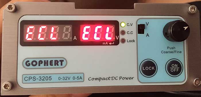
Upon unboxing, my initial impression of the CPS-3205 was very good. The unit is quite compact, nicely built, and easy to use. One trivial but annoying defect, however, is that the front panel meters are mislabeled. The voltmeter (on the left) is labeled A and the ammeter (on the right) is labeled V:

cps3205

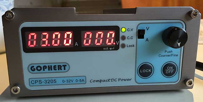
I can’t imagine how such a glaring error could have happened. The photos on Gopher’s website, and most photos from various vendors have the meters labeled correctly:

CPS-3205

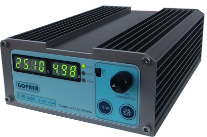
I started to wonder whether Banggood was selling counterfeits, also because mine is labeled GOPHERT rather than GOPHER. However, my fears were laid to rest when I found this photo on Gopher’s own website:

CPS-6003s-F

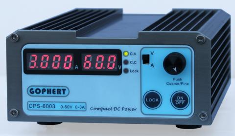
There are definitely genuine devices out there labeled GOPHERT and with the V and A reversed.

One important attribute of the CPS-3205 is that it doesn’t suffer from voltage transients at power up and power down, which can fry an attached circuit, unlike another cheap power supply I was considering, the PS-305D. Here is a test of the PS-305D’s nasty startup transient: Quick test of the PS-305D PSU. Although Voltlog’s testing shows that the CPS-3205 doesn’t suffer from startup voltage transients, there’s even a second layer of protection. By default, the outputs are disabled when it’s powered up. The ammeter displays OFF, and you must press the ON/OFF button on the front panel to enable the output. This further assures that the power is already stable by the time it reaches your attached circuit. Note that the ON/OFF button only controls the output. The main power switch is on the back of the unit. If, for some reason, you prefer to have the output enabled a power on, you can toggle this feature by holding the ON/OFF button depressed for 5 sec. If the ammeter displays dOn, then the output is enabled at power on, and if it displays dOF, then it’s disabled at power on.

The CPS-3205 has over current, over voltage, and over temperature protection, so it’s pretty robust.

I am not going to go into detail on operation of the CPS-3205, because it’s easy to read in the manual, and Voltlog demos it in his video. Suffice to say that the adjustment knob is very handy, because every time you press it, it shifts to a different digit to adjust, making it very fast to do fine or coarse adjustments. The LOCK button locks the adjustment knob and ON/OFF button from changes, and a nice feature is that it’s persistent even if you power the unit off/on.

WARNING: One attribute that’s not clearly stated in the manual is that in constant voltage (CV) mode, the current set in the constant current (CC) mode is an upper limit for the current that can be output. So, for instance, when the voltage is set to 25.00V and the current is set to 100mA, no more than 100mA can be output, so the output voltage will drop if you attempt to draw >100mA. I found this out the hard way, because mine had the current set to 000mA when I received it, so the output was zero in CV mode. I thought the unit was defective, as shown in my video:

After I played around with it some more, I realized that I had to switch it to CC mode and turn up the current before it would output any voltage.

Accuracy

I tested the accuracy of the CPS-3205 against a TES 2208 DMM. This TES meter has been my workhorse for the past 35 years or so, and has never been recalibrated. It’s no Fluke, but in my testing against other meters it’s been pretty good. That being said, I haven’t tested its accuracy in well over 15 years.

Out of the box, I tested a few random voltages in CV mode, and they were spot on. However, the ammeter displayed 5mA even when no current was flowing. Before running the tests below, I calibrated the CPS-3205 against the TES 2208 DMM, following the procedure at the bottom of this article. In the tables below, the readings are all shown to their maximum resolution.

The performance in CV mode was quite impressive, tracking to within .1V, and well within its rated spec of <=0.3% + 10mV.

Setting Panel Reading TES 2208 DMM
 00.01 00.02 .011
 00.05 00.05/00.08 .052
00.10 00.10 .101
01.00 01.01 1.006
05.00 05.00 5.01
05.25  05.25  5.26/5.27
10.00 10.00 10.03
 20.00 20.00 20.0
30.00 30.00 30.0
31.00 31.00 31.0
32.30 32.30 32.3

Generally, the voltage reacted to setting changes within a second, but when I dialed it down from 28.00V to 00.01V, it seemed like it took about a minute to ramp down and finally stabilize. Interestingly, at low voltages <=.10V, even though the panel meter displays on the high side, the actual output is actually quite a bit more accurate.

In CC mode, the performance was not as impressive, but within the rated spec of <=0.3%+20mA.

Setting Panel Reading TES 2208 DMM
001 005 5.7
005 009 9.7
10 15 14.8
20 23 25.1
50 53 55.1
55 56 66.8
60 65 66.8
70 75 77.0
80 90 87.2
100 104 105.3
180 185 187.2
190 197 197.3
200 207 .20
250 254 .25
1.00 1.00 1.00
1.20 1.20 1.20
1.21 1.21 1.21
1.22 1.22 1.22
2.25 2.25 2.25
3.25 3.25 3.25
4.00 4.00 4.00
4.05 4.05 4.05
5.00 5.00 5.00
5.10 5.10 5.10

While CC mode’s accuracy isn’t very good  it’s still within its rated spec. The .3%+20mA accuracy makes it basically useless at low currents, so  don’t use it for tiny loads, such as 20mA LED’s. The lower currents is where the PS-305D is a better performer.

I didn’t bother testing output ripple, because the accuracy of my CPS-3205 was very similar to that of Voltlog’s CPS-3205C, so I’m going to assume that the output ripple is similar. Also, I am not going to post teardown photos, because Voltlog’s video already goes over the innards of the CPS-3205C in quite some detail.

Summary

I am impressed that such an inexpensive piece of Chinese equipment is of such high quality. The CPS-3205 is well mode, easy to use, and surprisingly, comes from the factory fairly well calibrated. The user interface is well thought out.

Being a switch mode supply, it is light, compact, and quiet. Even though it’s fanless, it runs cool at the currents I tested.

One quibble I have is that the binding posts are in the rear of the unit. I wish that they were on the front panel, so I wouldn’t have to reach behind it. Also, the binding posts are lacking a hole drilled into the bolt for easy insertion of wires, and I wish the standoffs were a bit higher, so that they stood a bit farther away from the case.

The CPS-3205 not accurate enough for lab use, but for general hobby use, the performance is pretty impressive, as long as you can live with .3%+20mA accuracy on current control. It’s a great buy for the price. Currently, it can be had for <$50USD if you search around. It’s too bad that the current control isn’t better <100mA. It would have been nice to have the functionality to be able to run it between 5-25mA.

For those who want to re-calibrate the unit, it is easy to do, and the procedure is listed below.

Calibration Procedure

WARNING: ONCE YOU ENTER CALIBRATION MODE, YOU MUST COMPLETE THE ENTIRE PROCEDURE. IF CALIBRATION MODE IS ABORTED BEFORE COMPLETION, THE UNIT WILL ALWAYS DISPLAY ECP/ECP(OCP) AND BE NON-FUNCTIONAL UNTIL YOU COMPLETE A CALIBRATION CYCLE:

eclecl

A user has reported below that attempting the calibration procedure on a CPS-1610 resulted in the display getting stuck on ECL/ECL. Procede with caution and at your own risk. I myself have had no issues arise, and I have calibrated my two CPS-3205 units several times. However, !!!PROCEED AT YOUR OWN RISK!!!
1. Set V/A switch to A
2. Power on while adjustment knob is pressed in. PUSH OFF will be displayed
3. Press ON/OFF once, then LOCK twice. Display will be 03.00/001.
4. Hook up voltmeter to outputs and adjust output voltage to 3.00V with adjustment knob. Pressing the adjustment knob will toggle the sensitivity – ammeter will alternate 001/010 (001 is fine adjust, 010 is coarse adjust).
5. Press ON/OFF and display will be 30.00/001. Adjust output voltage to 30.00V
6. Hook up ammeter across outputs (dummy load is optional… the resistance in the leads is sufficient). Press ON/OFF and display will be 0001/1.00. Adjust current to 1.00A.
7. Press ON/OFF and display will be 0001/5.00. Adjust current to 5.00A.
8. Press ON/OFF and unit will return to normal operation, with OFF displayed and outputs disabled.

Maple Mini – Serial Programming and Upgrading to Bootloader 2.0

My BAITE BTE14-07 Maple Mini clone came with LeafLabs’ original bootloader. I decided to upgrade to Bootloader 2.0 in order to free up some RAM, and take advantage of some of the new features.

UPDATE: Roger Clark, the STM32DUINO guru, posted a comment below, informing me that you can upload to Bootloader 2.0 by simply loading the updater sketch, without a USB->UART adapter, so you can try that first, and save my procedure below for if it somehow fails and bricks your Maple Mini.

The procedure looks pretty straightforward, but I ran into some snags. Perhaps the easiest way to change the bootloader in a Maple Mini is to use the STM32’s built-in serial bootloader to flash it in. The serial bootloader is in ROM, so it’s a fail-safe method to program the chip. The technique involves hooking up UART1 to a USB->UART adapter. I had a spare CP2101-based adapter that works with 3.3V hardware:

CP2102_0

The hookup is straightforward:

TX -> rx1
RX -> tx1
3V3 -> Vcc
GND -> GND
BOOT1 ->GND

Here is what it looks looks like all hooked up:
bootloader

Actually the RX1 & TX1 pins are 5V tolerant, so you can even use a 5V USB->UART adapter. Just make sure to hook up 5V -> vin instead of to Vcc, or you’ll be in for a very unpleasant surprise.

There are several programs available that can program the STM32 in serial bootloader mode. I tried both stm32load.py and stm32flash. Also, you will need the binary bootloader file, maple_mini_boot20.bin.

To put the board into serial bootloader mode, press and hold reset and but, release reset, and then release but. The board will look dead. This is normal. Then execute the command to flash in the bootloader. stm32flash is more straightforward, because it doesn’t require you to install Python. There are pre-compiled versions of stm32flash for various platforms in Arduino_STM32’s tools directory. My computer runs Windows 8.1, so I used the stm32flash.exe:

C:\git\Arduino_STM32\tools\win>stm32flash -w maple_mini_boot20.bin COM19 -b 230400 -g 0
stm32flash 0.4

http://stm32flash.googlecode.com/

Using Parser : Raw BINARY
Interface serial_w32: 230400 8E1
Version : 0x22
Option 1 : 0x00
Option 2 : 0x00
Device ID : 0x0410 (Medium-density)
– RAM : 20KiB (512b reserved by bootloader)
– Flash : 128KiB (sector size: 4×1024)
– Option RAM : 16b
– System RAM : 2KiB
Write to memory
Erasing memory
Wrote address 0x08001b7c (100.00%) Done.

Note that you need to substitute your USB->UART converter’s serial port for COM19.

If you prefer Python, you can use stm32load.py instead. Make sure to use the version from the Arduino_STM32/tools directory. I tried to use the version from STM32duino-bootloader and the version from libmaple, and both of them wrote only the first 512 bytes of the bootloader, so the Maple Mini was no longer detected at all when plugged into my computer.

Here is how to execute stm32loader.py:

C:\git\Arduino_STM32\tools\win>stm32loader.py -p COM19 -evw \hacking\STM32\maple_mini_boot20.bin
Reading data from \hacking\STM32\maple_mini_boot20.bin
Bootloader version 0x22
Chip id 0x410, STM32F1, performance, medium-density
Writing 7036 bytes to start address 0x8000000
Write 256 bytes at 0x8000000
Write 256 bytes at 0x8000100
Write 256 bytes at 0x8000200
Write 256 bytes at 0x8000300
Write 256 bytes at 0x8000400
Write 256 bytes at 0x8000500
Write 256 bytes at 0x8000600
Write 256 bytes at 0x8000700
Write 256 bytes at 0x8000800
Write 256 bytes at 0x8000900
Write 256 bytes at 0x8000A00
Write 256 bytes at 0x8000B00
Write 256 bytes at 0x8000C00
Write 256 bytes at 0x8000D00
Write 256 bytes at 0x8000E00
Write 256 bytes at 0x8000F00
Write 256 bytes at 0x8001000
Write 256 bytes at 0x8001100
Write 256 bytes at 0x8001200
Write 256 bytes at 0x8001300
Write 256 bytes at 0x8001400
Write 256 bytes at 0x8001500
Write 256 bytes at 0x8001600
Write 256 bytes at 0x8001700
Write 256 bytes at 0x8001800
Write 256 bytes at 0x8001900
Write 256 bytes at 0x8001A00
Write 256 bytes at 0x8001B00
Read 256 bytes at 0x8000000
Read 256 bytes at 0x8000100
Read 256 bytes at 0x8000200
Read 256 bytes at 0x8000300
Read 256 bytes at 0x8000400
Read 256 bytes at 0x8000500
Read 256 bytes at 0x8000600
Read 256 bytes at 0x8000700
Read 256 bytes at 0x8000800
Read 256 bytes at 0x8000900
Read 256 bytes at 0x8000A00
Read 256 bytes at 0x8000B00
Read 256 bytes at 0x8000C00
Read 256 bytes at 0x8000D00
Read 256 bytes at 0x8000E00
Read 256 bytes at 0x8000F00
Read 256 bytes at 0x8001000
Read 256 bytes at 0x8001100
Read 256 bytes at 0x8001200
Read 256 bytes at 0x8001300
Read 256 bytes at 0x8001400
Read 256 bytes at 0x8001500
Read 256 bytes at 0x8001600
Read 256 bytes at 0x8001700
Read 256 bytes at 0x8001800
Read 256 bytes at 0x8001900
Read 256 bytes at 0x8001A00
Read 256 bytes at 0x8001B00
Verification OK
Traceback (most recent call last):
File “C:\git\Arduino_STM32\tools\win\stm32loader.py”, line 531, in
if conf[‘go’]:
KeyError: ‘go’

I don’t know what’s the cause of the error at the end, but as long as it writes 7036 bytes, you see Verification OK, the bootloader is installed correctly. Whe I ran the bad versions of stm32loader.py, here is what the output looked like:

Bootloader version 22
Chip id `[‘0x4’, ‘0x10′]’
Write 256 bytes at 0x8000000
Write 256 bytes at 0x8000100
Read 256 bytes at 0x8000000
Read 256 bytes at 0x8000100
Verification OK

Even though it showed Verification OK, note how only 512 bytes were written to the Maple Mini.

If you have successfully flashed in the bootloader, the LED will flash continuously after you reset the board, indicating that the bootloader is running. In Arduino, you also must switch the setting to from Original to Bootloader 2.0:

selectbootloader

If, for some reason, you want to revert to LeafLabs’ original bootloader, you can download it here: maple_mini_boot.bin.

The built-in STM32 serial bootloader is not only for installing bootloaders. You can also use it to flash in any other BIN file, including Arduino_STM32 sketeches.

First Look: BAITE Maple Mini Clone

Recently, I’ve been searching around for inexpensive higher powered alternatives to AVR-based Arduinos. There are several ARM MCU’s available that give a lot more bang for the buck in terms of RAM, speed, flash, and I/O. While I like PJRC’s Freescale-based Teensy 3.x boards a lot, they’re only available from a single source, and use a proprietary bootloader hosted on a separate MCU. FadeCandy is an OSHW board based on the same MCU as the Teensy 3.0, which is optimized for controlling LED’s. Unlike the Teensy 3.x, it uses an open source bootloader which is hosted on the Freescale MCU itself.

There are a lot of STM32 boards of various types available on eBay and AliExpress. LeafLabs’ Maple series of STM32 boards were pioneers in adapting Arduino for use with the STM32 platform. Unfortunately, the boards were quite expensive, and with the proliferation of cheap Chinese clones, they business was not sustainable, and they discontinued the line. Luckily, the OSS community has picked up the pieces, notably Roger Clark’s Arduino_STM32 project. The current state of the project is very impressive. Not only has Arduino compatibility been greatly improved, but they have created a new bootloader, and many other STM32 families are not supported beyond the Maple’s STM32F1.

I decided to dive in when I had a project that needed 10 PWM channels. The Maple Mini fit the bill. I bought a couple of BAITE BTE14-07 Maple Mini clones. They are quite cheap, under $4.50 including shipping from China. The board is packaged in an anti-static bag, and includes header pins:

BTE-1407f

BTE-1407bb

While the pinouts, LED, and buttons of the BAITE BTE14-07 are identical to the original LeafLabs Maple Mini, the BAITE version is only 2-layer, instead of 4-layer. Also, instead of using two MCP1703 voltage regulators, one for the digital and one for the analog plane, the BAITE uses a single AMS1117. This means that LeafLabs version is probably more suitable for applications where ADC accuracy is required, but the BAITE version is better when more current is needed to drive attached peripherals.

I tried some sample sketches using Arduino 1.6.5 and Arduino_STM32, and the BAITE board worked perfectly. Some people on the STM32duino board consider it to be somewhat of a benchmark as far as Maple Mini clones go, so it’s probably a good bet for n00bs to the platform like me.