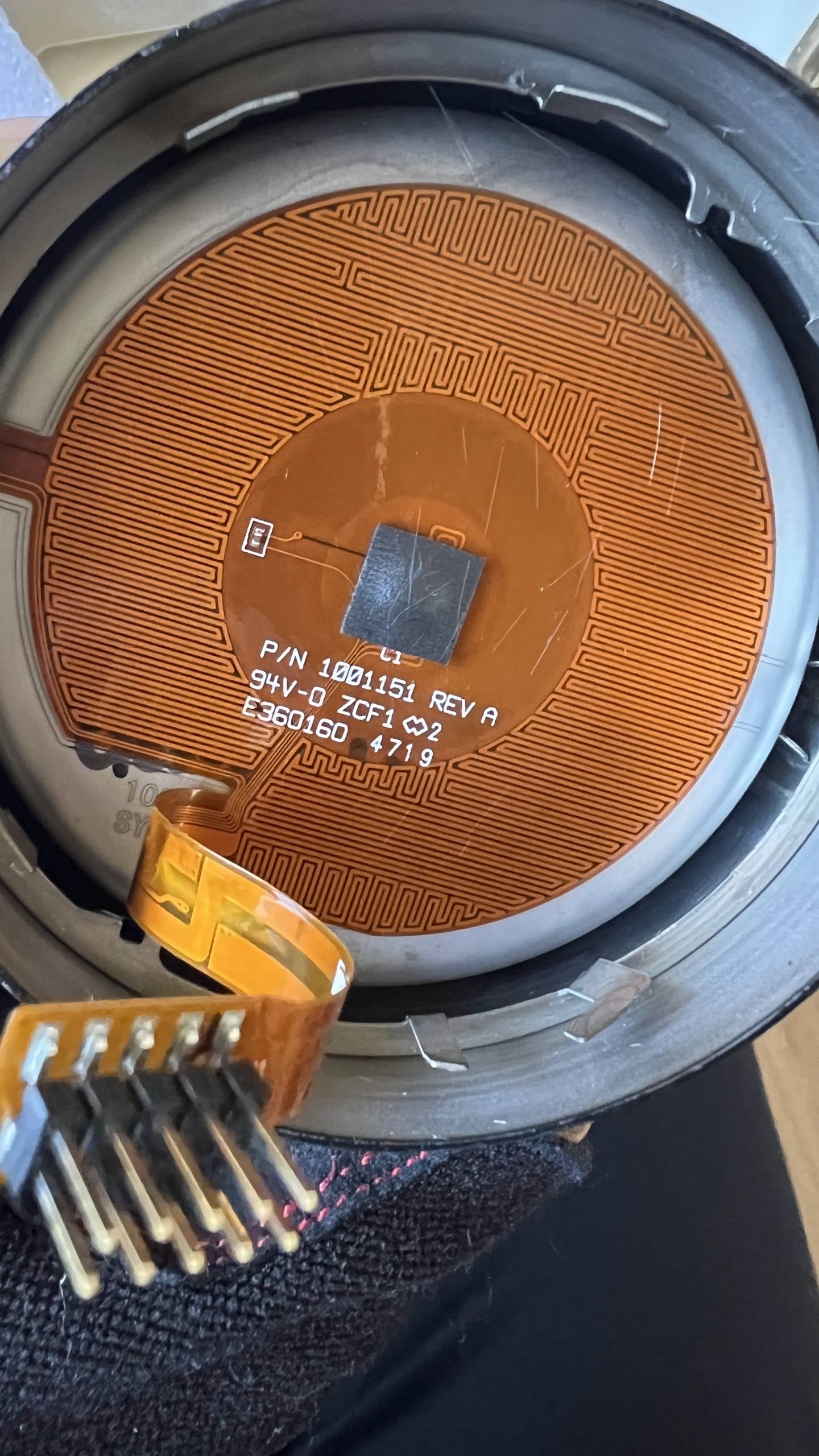
My previous article left off with the task of figuring out what kind of temperature sensor is in the Ember Mug 2. I removed the black rubber retaining ring in the bottom of the mug, and then the 2 aluminum plates which cover the white insulation disc easily came out. Behind it was this:
The very long grid of PCB traces is the heater. There are 3 wires going off into a narrow strip on the left of the photo above to a mystery component that’s sandwiched between the inside/outside of the mug. I think it’s glued in, and can’t be accessed w/o destroying it.
And below the black rubber square is this:
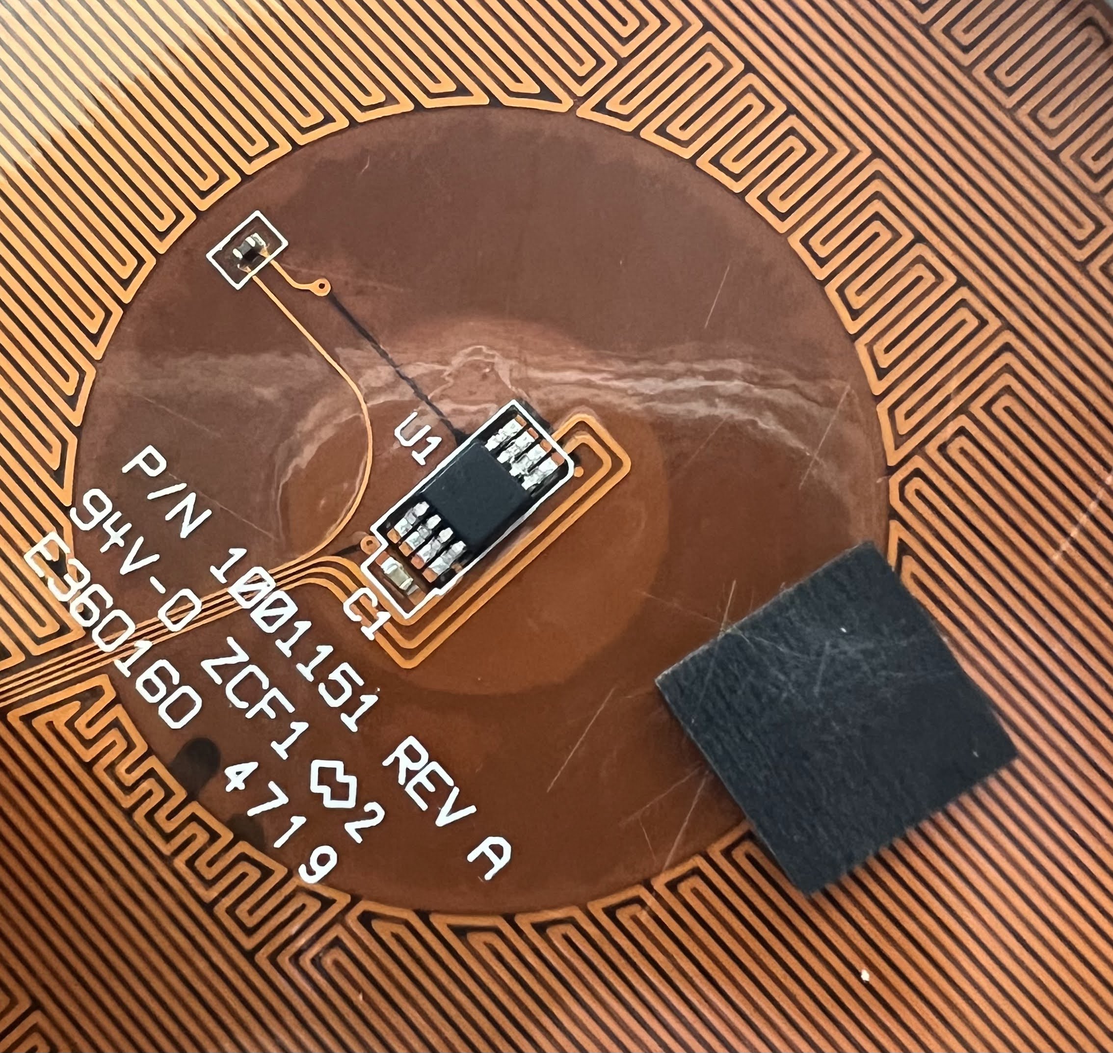
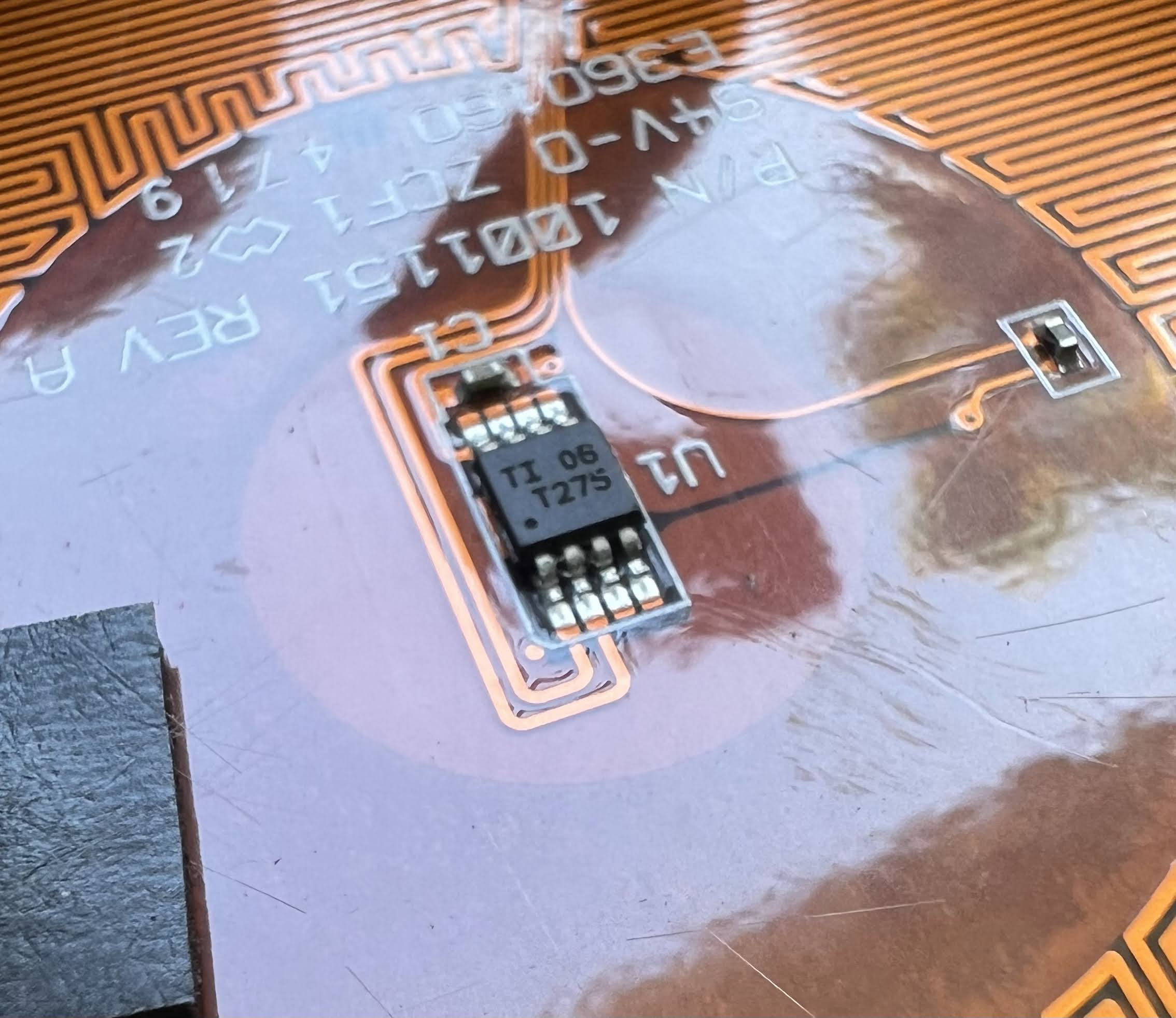
Is U1 the temperature sensor? Here is a close up:
The temperature sensor is just a common part, a TMP275. I have already interfaced a TMP275 to an ESP32 for a previous project of mine. There is plentiful library code already written for reading a TMP275/LM75.
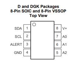
Here is the pinout of the TMP275:
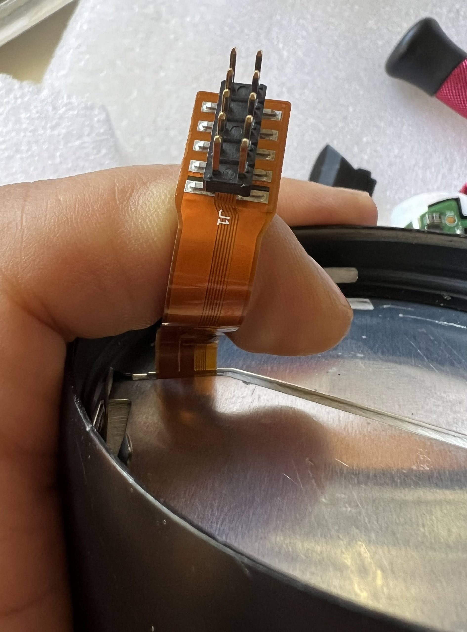
The 2×5 pin connector on the end of the flex cable is labeled J1. Looking at it from the pins side, and w/ J1 on the top, here are the connections I’ve figured out so far:
(1) Heater2
(6) Heater1
(2) Heater3
(7) TMP275 GND
(3)
(8) TMP275 SCL
(4)
(9) TMP275 SDA
(5) unlabeled cap- other end of cap to TMP275 A0/A1/A2
(10) TMP275 V+
SCL & SDA need to be pulled up with 5K resistors (these are probably on the main PCB)
I’m not sure what (3) & (4) connect to, but most likely, it’s the mystery component that’s connected by 3 traces up the side of the cup.
The heater connections are a bit puzzling:
Resistance Heater1-Heater2 11.8 ohms
Resistance Heater2-Heater3 13.8 ohms
Resistance Heater1-Heater3 2.4 ohms
It appears that there are 2 heaters in series with a center tap. I’m guessing that both are used in parallel during heating, and only one is used to maintain temperature.
I’ve already spent too much time on this today, so I’ll have to continue in Part 3.
On the surface, the Ember Mug sounds like a completely idiotic product. I mean, who needs a %#$ bluetooth mug? However, I like to drink coffee and tea, and it has been a constant irritant over the years that my coffee or tea are always either too hot or too cold. Especially tea. I tend to sip it over a long period, and it’s always either burning hot or too cold.
One day, my wife got an Ember Mug 2 as a gift. Actually, it turns out to be pretty useful. It keeps your drink at whatever temperature you like. I decided to get myself used Ember Mug 2. I paid $58, which is still way too much, but it’s a lot cheaper than the $150 a new one cost at the time.
The bluetooth is still idiotic. I would much prefer a mug w/ manual temperature control and buttons on the side. The app just complicates things. Furthermore, the firmware is absolute garbage. Since there’s no switch to turn it on or off. It tries to figure out if there’s liquid inside by sensing how fast the temperature changes when the heater is on. Unfortunately, the idiotic firmware also assumes that the mug is empty when you put in a drink that’s too cold. It refuses to heat up, even if you try to override via the app.
One day, I had some cold coffee that had been sitting out too long. I put it in the Ember Mug to warm it up. It refused to heat up my drink, since it was too cold. Being half asleep, I put it in the microwave oven to warm up the drink to a temp where the Ember Mug would recognize that it wasn’t empty. HORROR OF HORRORS! After about 30s, I realized that I had put my non-microwaveable Ember Mug into the oven!!! I turned off the oven, but alas, it was too late. The mug continued to talk to the app for a few minutes, but refused to heat. A few minutes, it completely died, never to wake up again. I’m lucky that I didn’t microwave it long enough to cause the lithium ion battery to catch on fire, and destroy my oven!!!
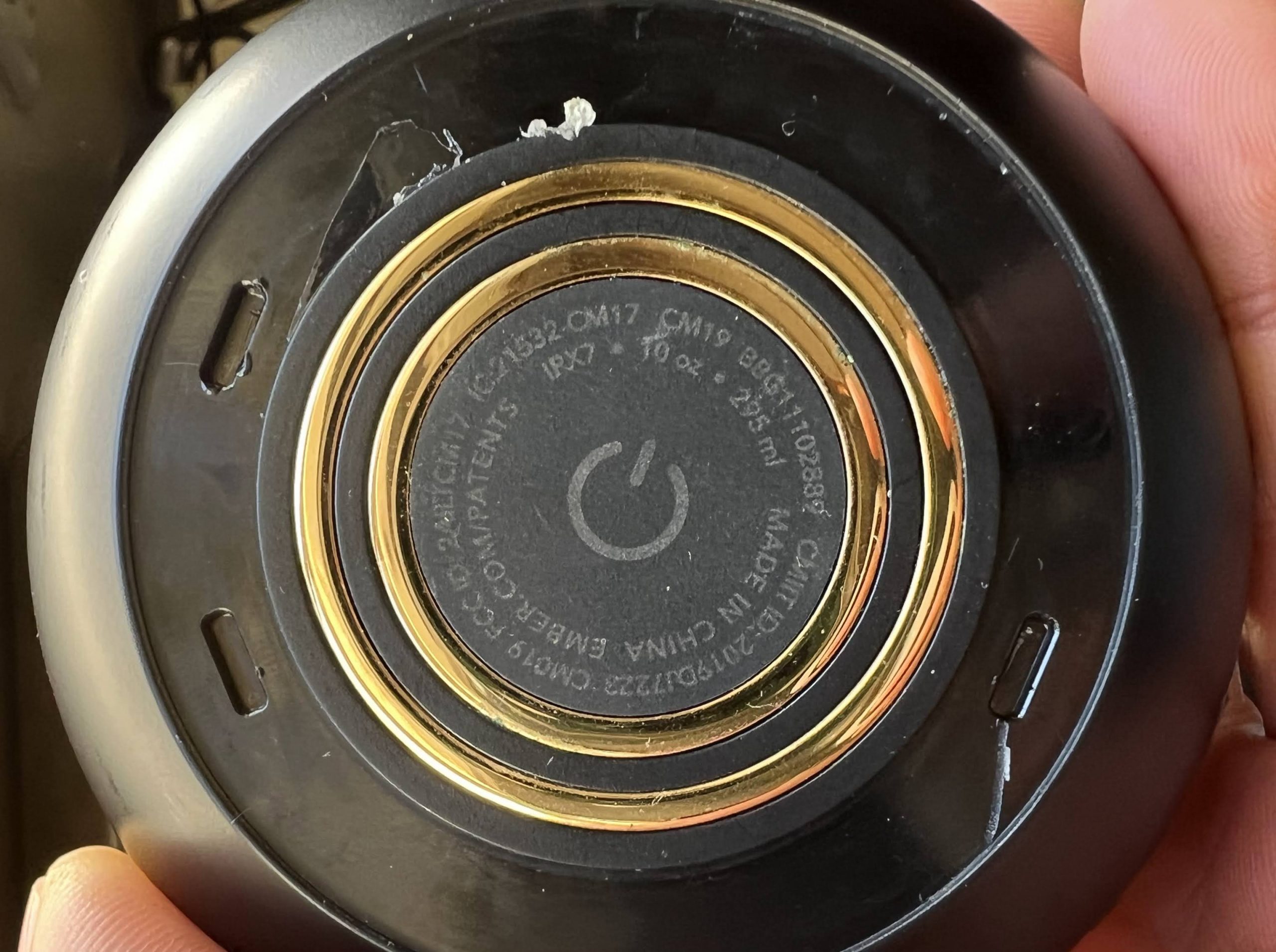
I scoured the Internet, looking for information on how to take it apart. I was hoping that maybe I got lucky, and only the battery got damaged… all I had to do was figure out how to replace it. Unfortunately, I couldn’t find anybody who’d actually taken apart an Ember Mug 2. There is lots of info on taking apart the Ember Travel Mug. However, that one’s bottom is held on with just screws. Not the Mug 2. I took off the rubber gasket on the bottom, and this is what I found:
Unlike the Travel Mug, there are no screws under the gasket. I tried rotating the bottom using the slots, but was not successful.
At this point, I decided to contact Ember tech support, because I heard that they offer cheap replacements to idiots who damage their mugs in the microwave. I emailed Ember tech support, and got this response:
Thank you for reaching out to Ember support! Your request has been received. We are currently experiencing longer reply times, but our team is working diligently to get back to you!
Yeah, right. It’s been 3 weeks, and they still haven’t gotten back to me! <rant> Ember is a shitty company! They sell such a ridiculously expensive disposable, unrepairable product, and have non-existent tech support.</rant> (Update 20240112: Ember actually did try to get back to me 2 days after I opened my support ticket w/ an offer to sell me a new mug at reduced cost, but somehow, the message never got to me. A few hours after I posted this article, I received a message from them saying the ticket would be closed soon due to inactivity.)
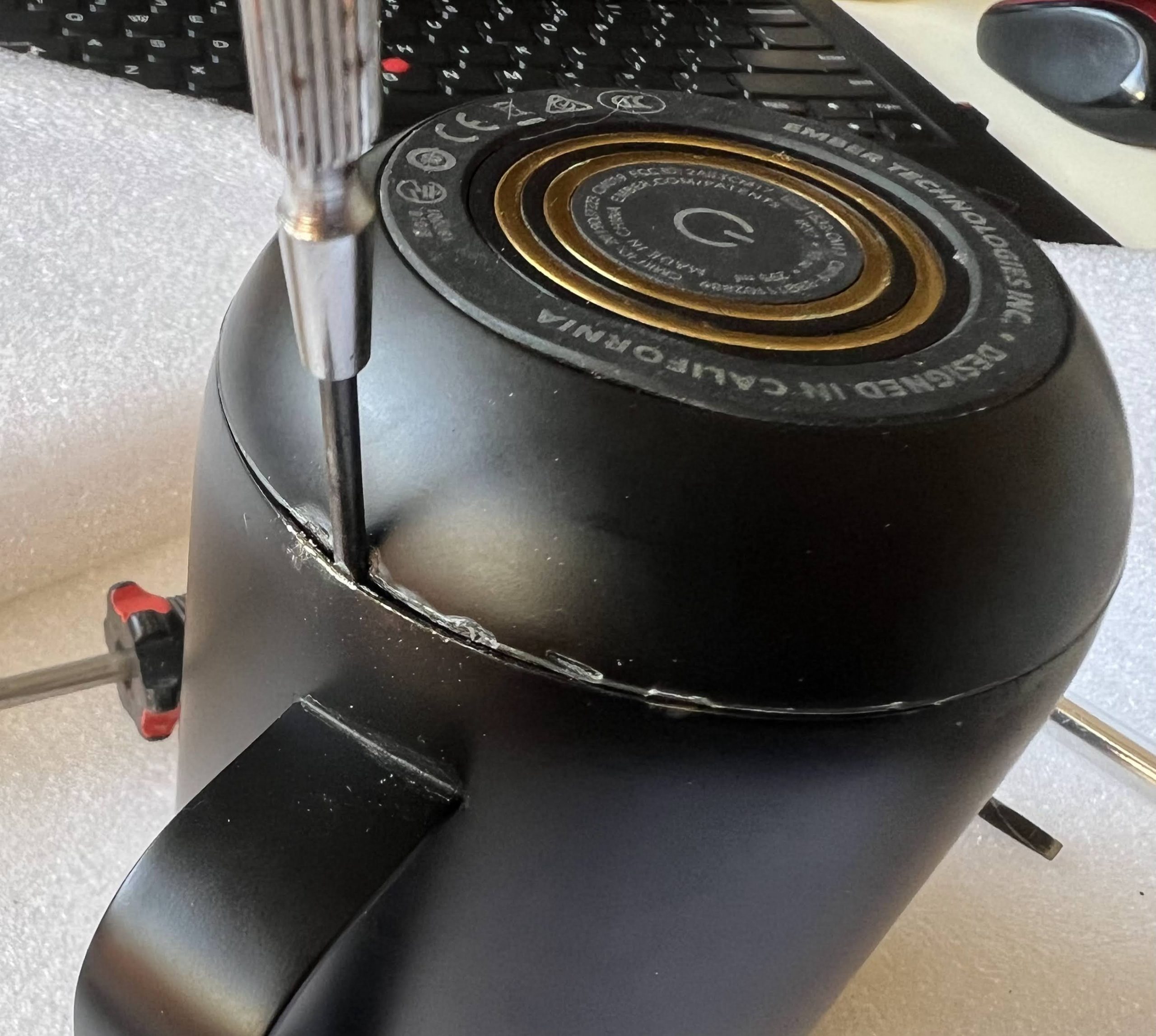
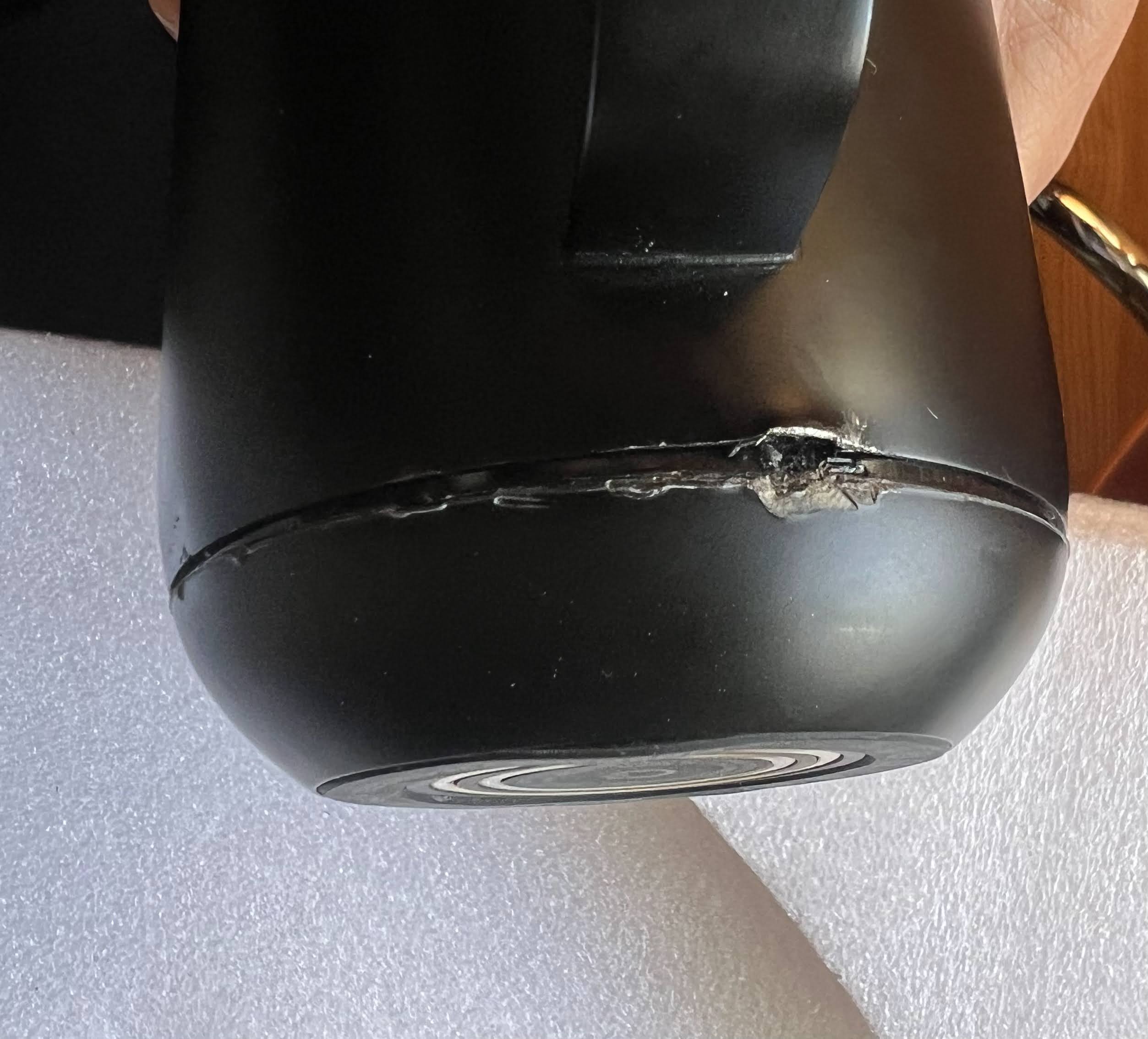
OK, so I decided to disassemble my mug this morning. First, I went around the seam at the bottom with an x-acto knife. It didn’t come loose. Next, I drove a screwdriver into the seam and tried to pry. I chose a spot under the handle, so that the damage wouldn’t be as visible. Finally, I drove my screwdriver between the metal casing and the plastic bottom:
Finally, some movement.
I wedged a bigger screwdriver in, and pried harder. The bottom finally came off:
Well lookie there! It’s a twist off bottom after all! It’s too late for me, but I think one could easily drive 3 brads into a piece of wood, lining up w/ the slots I revealed in my first photo … rotate clockwise, and twist off the bottom w/o damaging anything! (UPDATE: The guy who wrote the iFixIt article linked at the bottom claims that the vertical aluminum strip at 10 o’clock prevents the bottom from being twisted off. If that’s the case, it’s a bit of assholery by Ember to keep the mugs from being serviced. Sheesh, it’s bad enough they didn’t just screw the bottom on like w/ the Travel Mug).
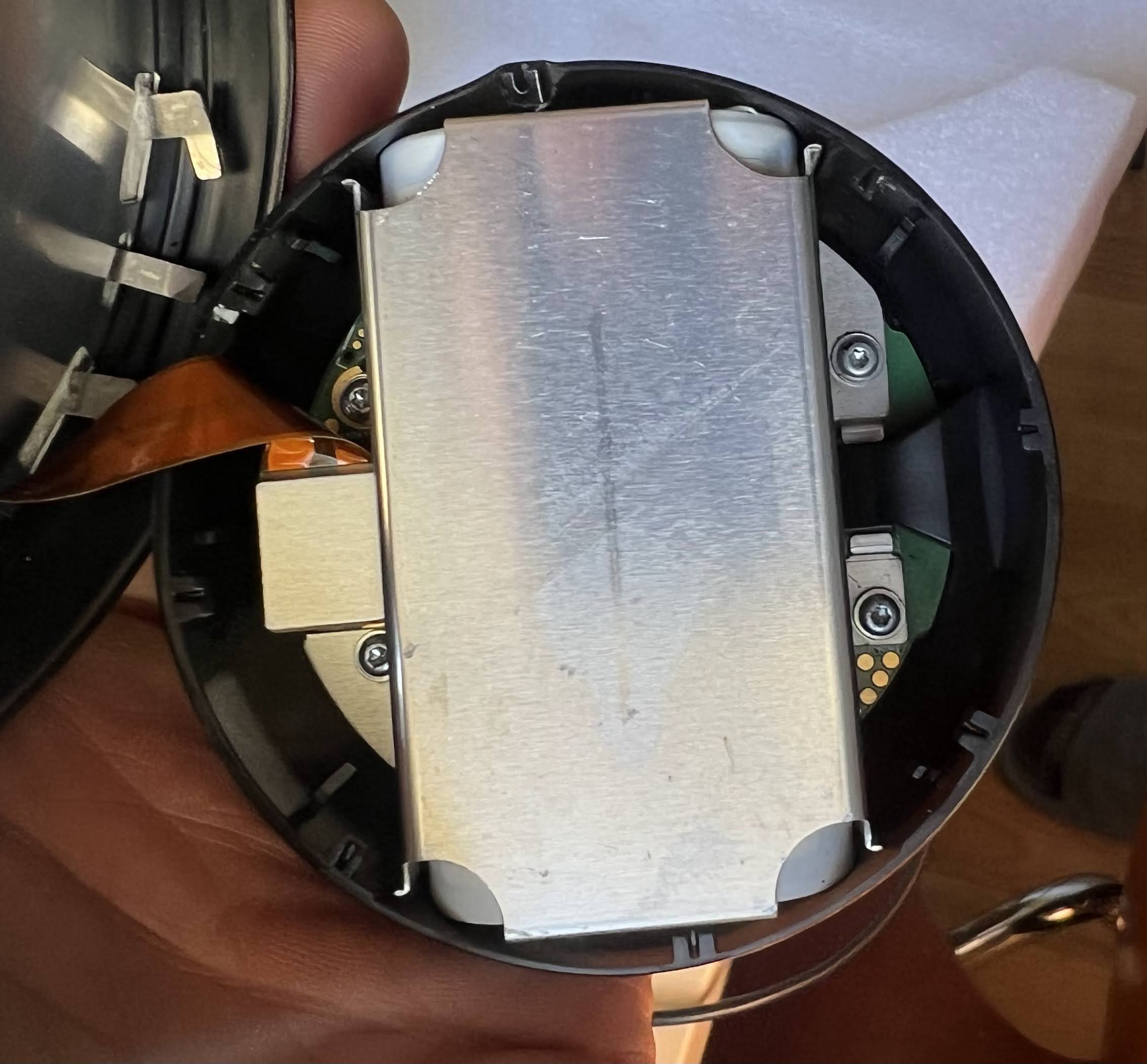
The second I had the case cracked open, the smell of burnt electronics emanated. I instantly knew that I would be dealing w/ more than a damaged battery. The battery is covered by an aluminum plate, which is held on by 4 torx screws:
The 4 torx screws also secure the PCB to the bottom of the case. However, I still couldn’t get the PCB out after taking out the screws. There was a piece of plastic holding down the PCB. You can see it on the right side in the photo below:
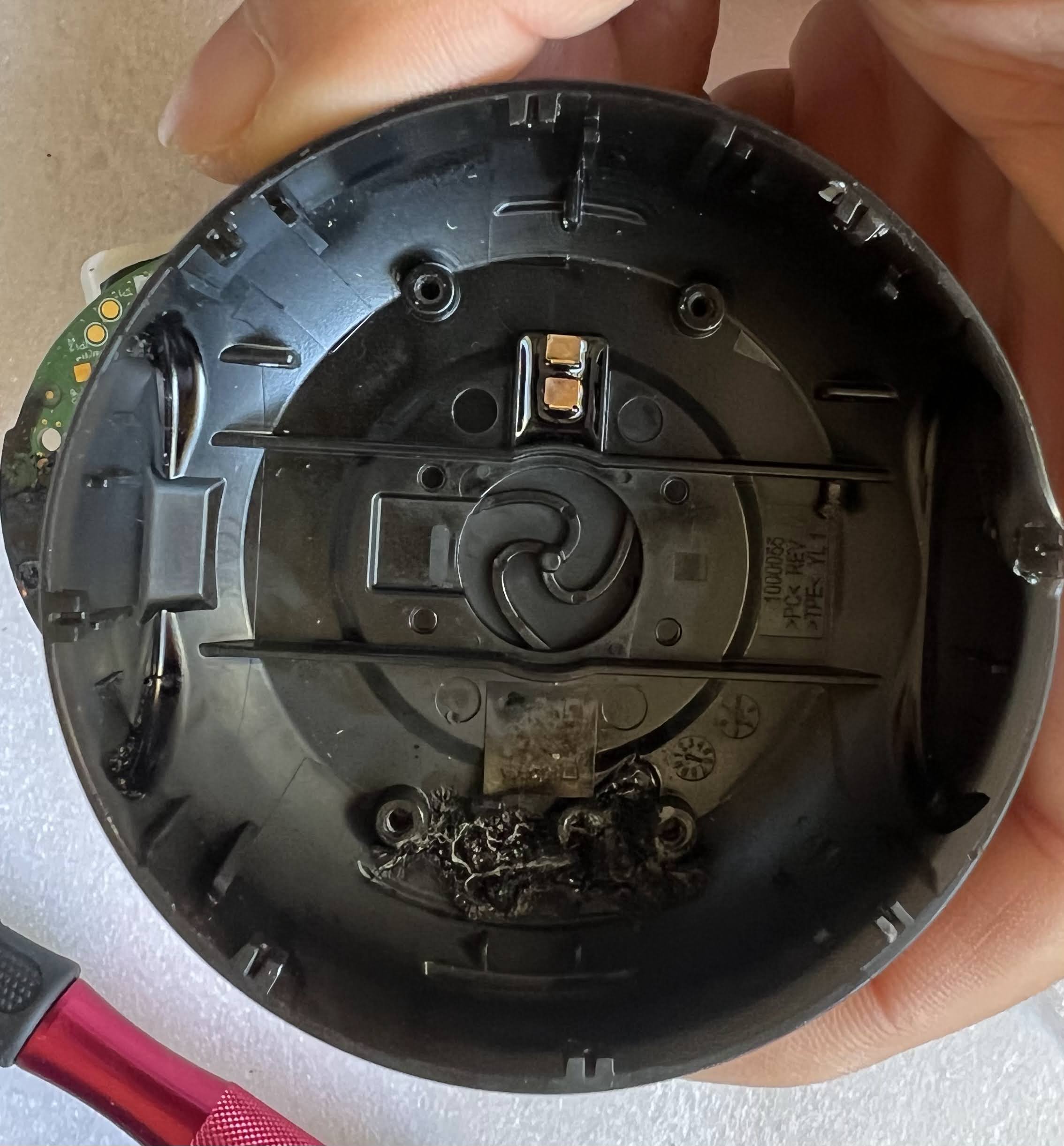
I rotated the plastic part out of its retaining slot. Bad idea. It turns out that it’s a light pipe for the RGB LED. Rotating it broke the LED from the PCB:
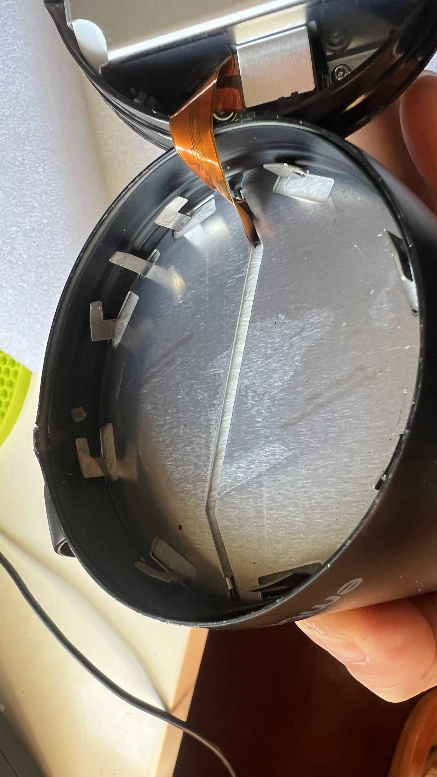
Note that there’s also a monochrome COB LED behind it. I wonder why they need 2 separate LEDs. Here’s what my burnt out plastic bottom looks like inside:
The 2 gold pins in the top center are contacts from the charging ring on the other side. The small circular pin dead center is the pushbutton on the bottom of the mug, which actuates a small SPST switch on the bottom of the PCB
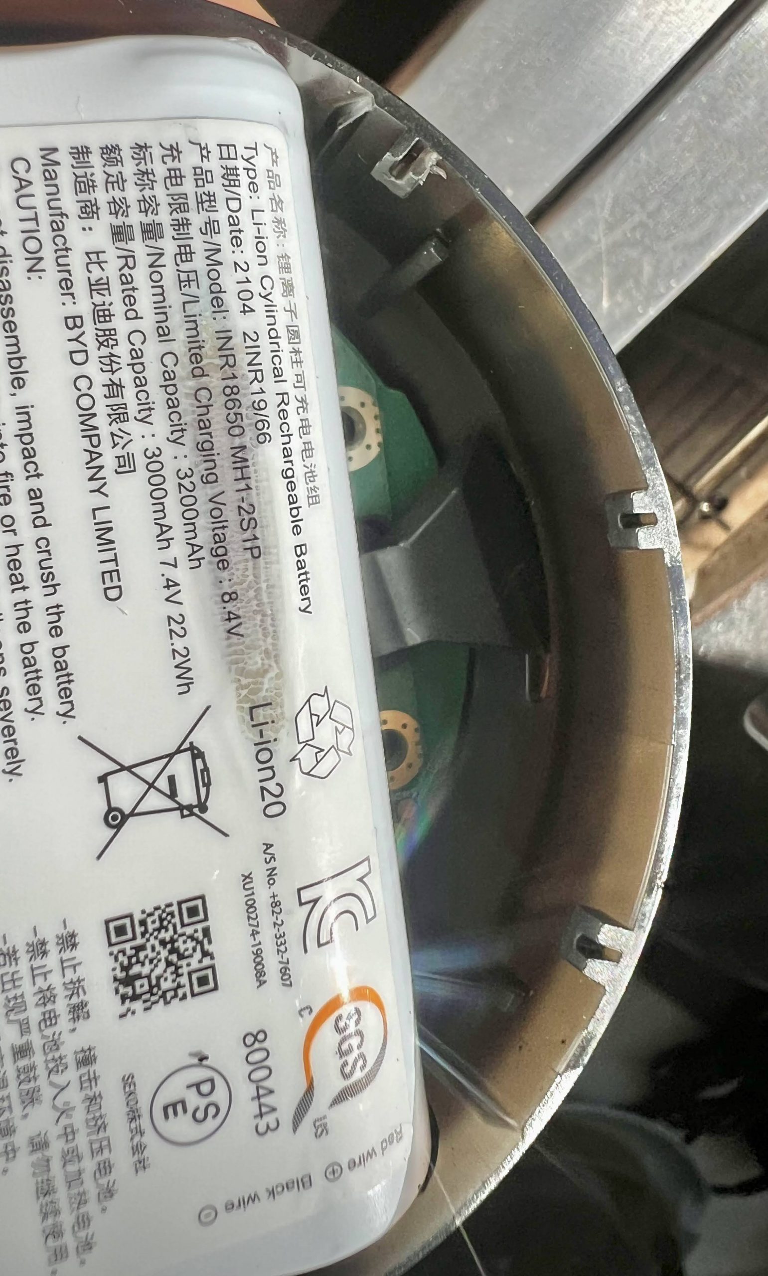
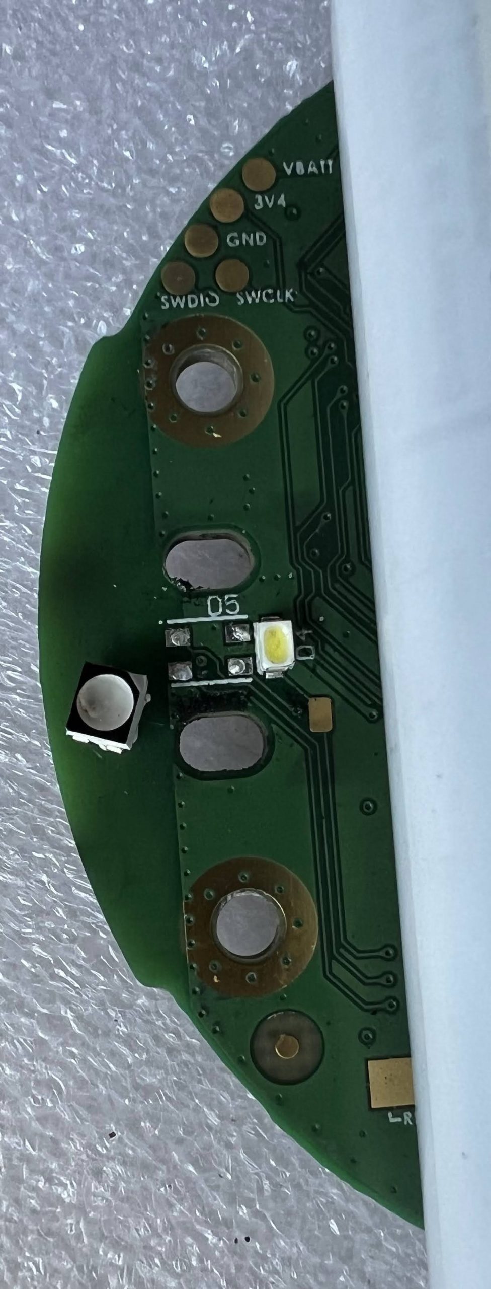
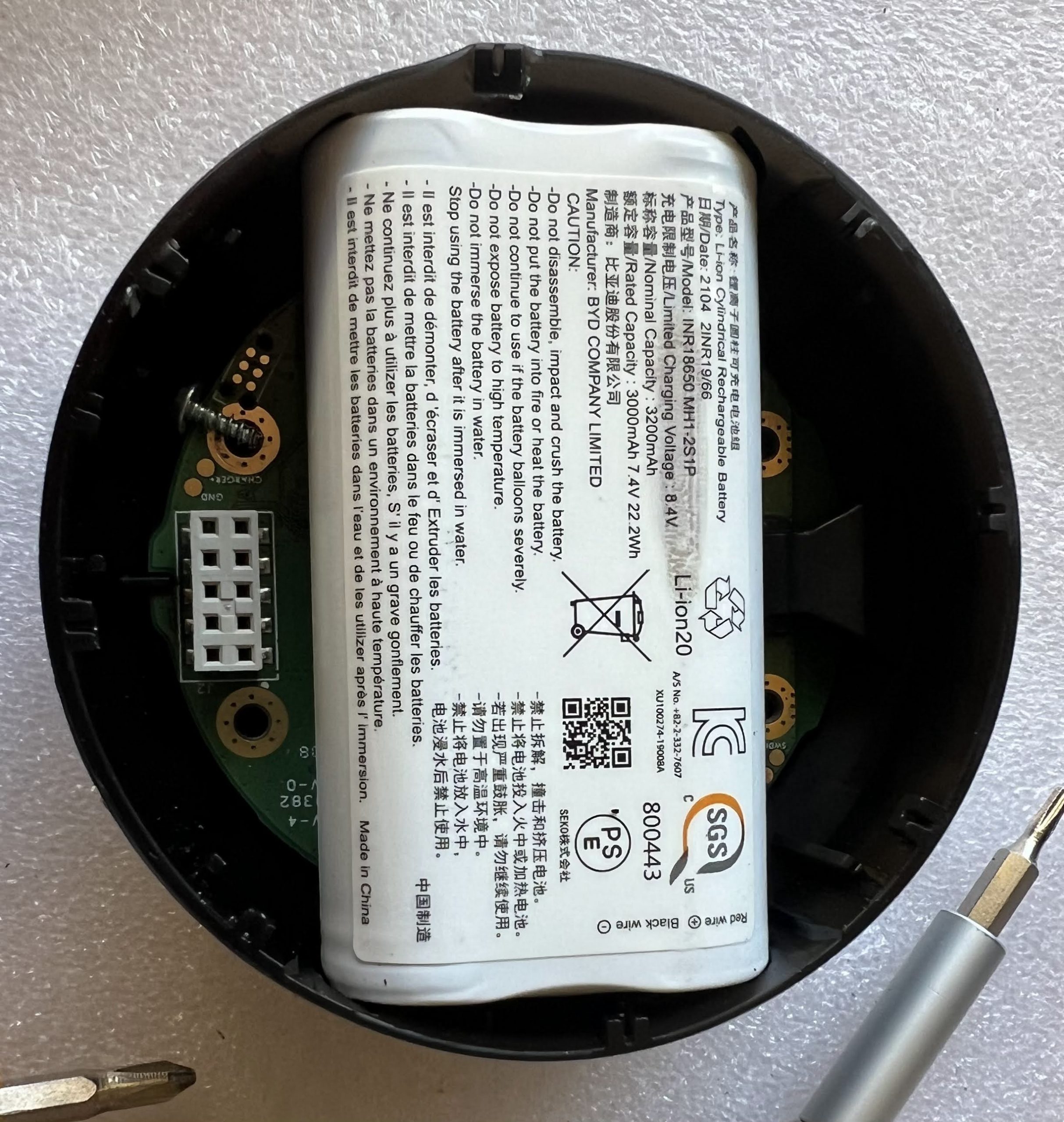
The battery is just a couple standard 18650 cells welded together in a plastic casing, along with the protective circuitry. If you have a Mug 2 with a worn out battery, Ember won’t sell you a replacement. It’s not to hard to just rebuild the pack w/ two new 18650 cells. Here’s my scorched PCB:
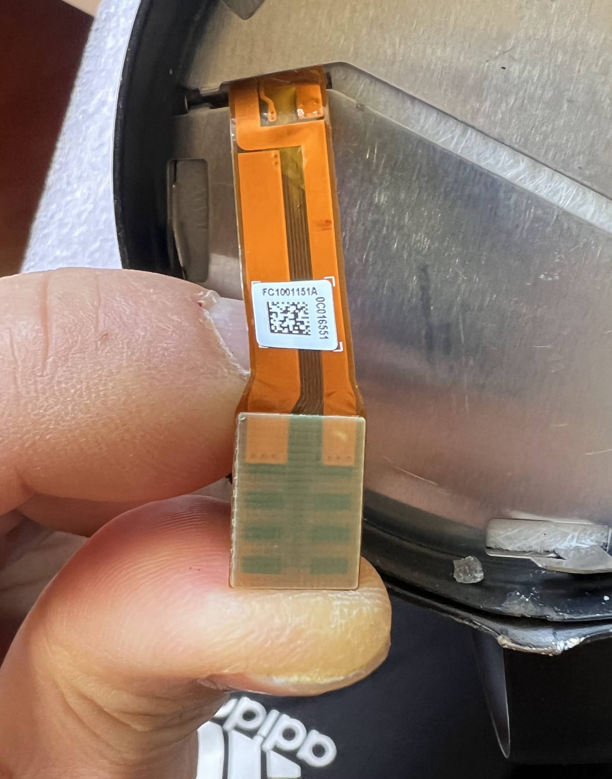
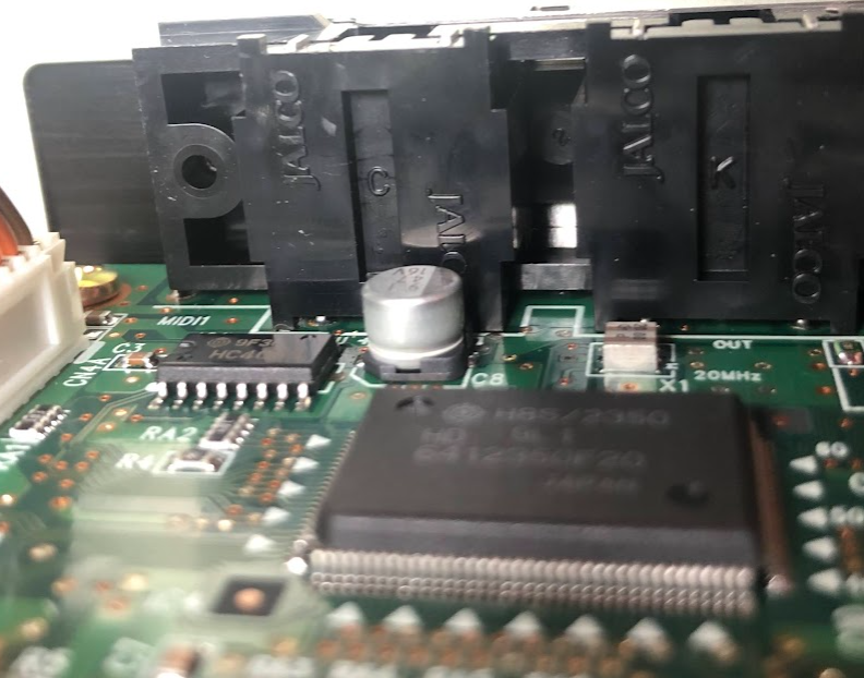
The battery connector is on the bottom of the photo above. I measured the voltage between the red and black wires, and it was zero. The yellow and green are sense wires. I am not going to even try to apply 7.4V to the burnt PCB to see if it still works. Here are closeups of the connector that goes into the top of the mug:
It’s obvious that the fat traces are for the heater. Next, I need to figure out what voltage/current the heater needs, as well as what kind of temperature sensor is attached at the other end.
It will be non-trivial, but not too difficult to cook up a circuit w/ an ESP32, along with firmware to resurrect my Ember Mug 2.
UPDATE 2022-08-31: It turns out that in order to program Honda key fobs for cars w/ a push to start button (one button start), you need to be running the beta Honda module V2.01.54, which only runs on 64-bit Android phones, and which you must request from Autel (Instructions here: https://clarity-phev.github.io/Battery-Capacity-Read/AP200_Instructions.pdf). The regular Honda module only programs keys via a separate external module, which plugs into the car’s DLC port. If you aren’t able to obtain the beta Honda module, then you’re out of luck, unfortunately.
Several months ago, I misplaced one of the key fobs from my 2019 Honda Clarity. The MSRP of the fob itself is $467, and I found the OEM part online for $314. Local locksmiths all wanted $150 to program it. Outrageous.
I started searching around for cheaper sources of fobs, and found one on eBay for $22.24:
I was pleasantly surprised when I received it. It’s pretty much identical to the OEM part, except that the spot for a plastic insert in the back is empty. It even comes with a blank key, which slides out, just like the original. Next, I had to figure out how to program it. I called a bunch of locksmiths, and they all wanted $150 to program it, which is crazy. Then I remembered that I had an Autel MaxiAP200 bluetooth dongle, which I used for OBD-II diagnostics.:
It’s a steal, because it can do most of the functions that their standalone professional OBD-II units can do, but a fraction of the price. I bought mine on AliExpress for $50 from the official Autel store (the price is higher on the screenshot above). You can also find them on Amazon. Autel sells several different models of bluetooth dongle at different price points. Make sure to buy the MaxiAP200. The other models force you to pay an annual fee, while the MaxiAP200 includes a lifetime license for one vehicle make, with free updates. You can add on other makes later on, but they will need to be renewed annually. It connects to both Android an iOS phones. I will not go into how to install the app and pair the device, because you can find that info elsewhere.
Anyway, I started looking around the functions that were available in the app, and discovered that it has the capability to program key fobs! I will walk you through the easy procedure. Note: Some of the screens may be missing in the walkthrough below.. there were so many that I think I forgot one or two, but the app walks you through step-by-step. Just follow the prompts.
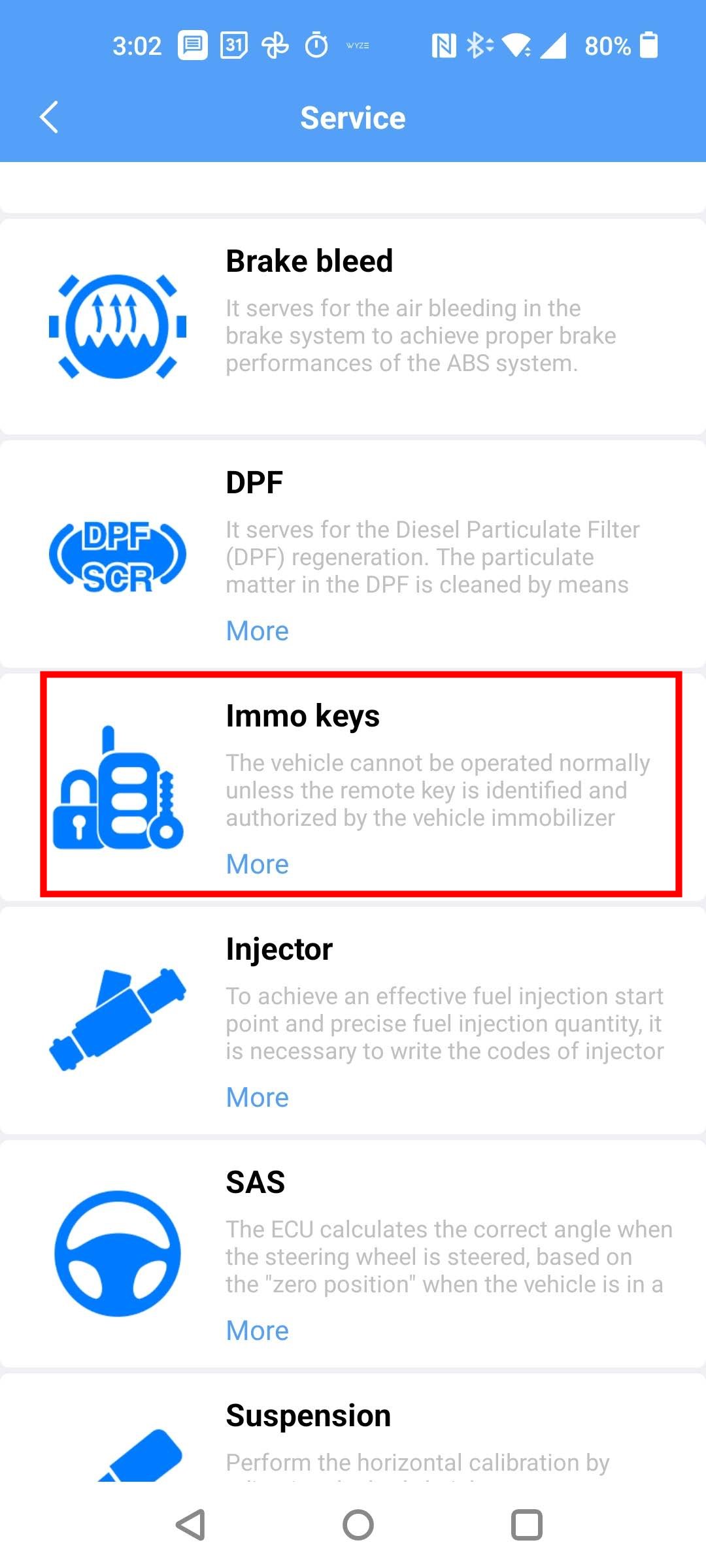
Launch the MaxiAP200 app on your phone, and select Service from the main menu.
Next, select the Immo Keys module:
Then select your vehicle brand:
Next, you’ll be prompted to select the vehicle:
Then your vehicle’s country of sale:
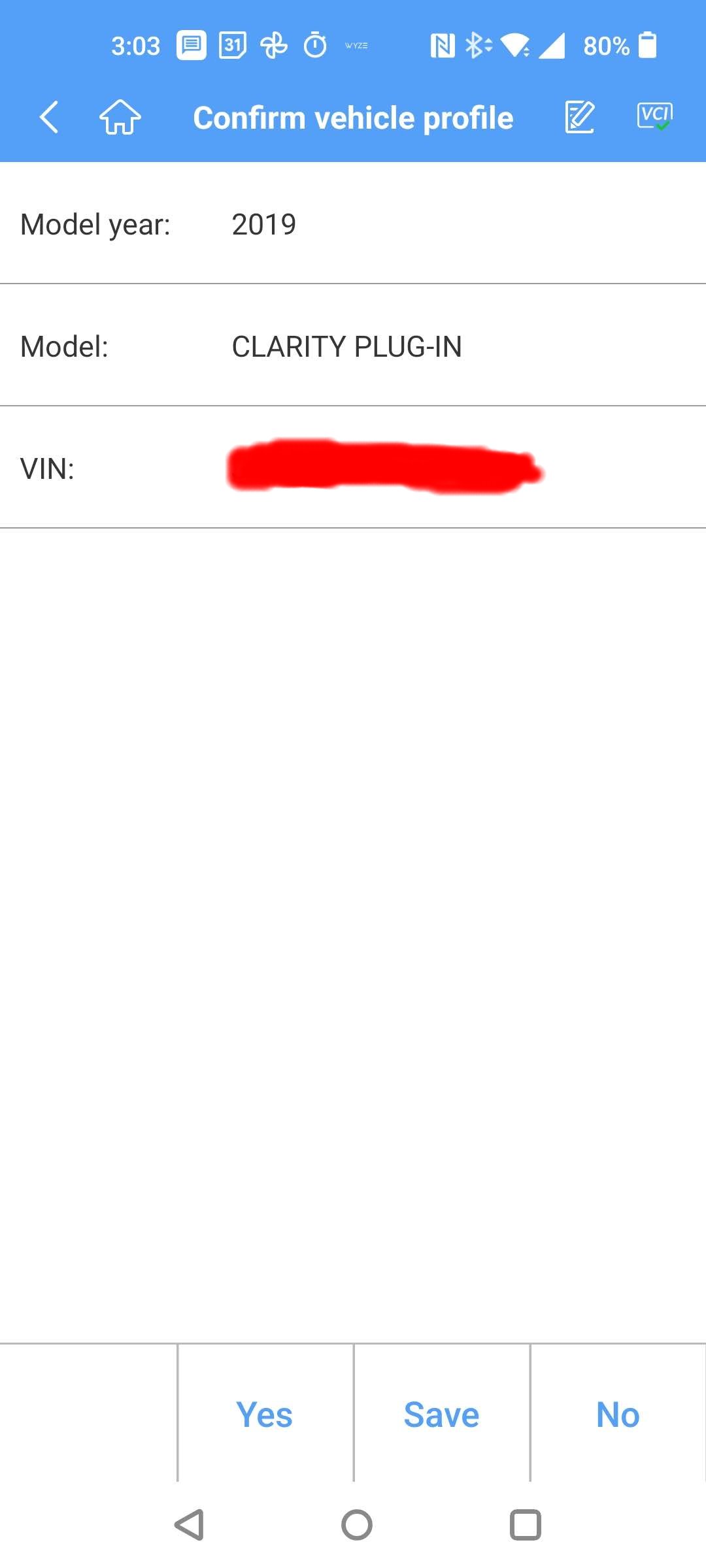
It will scan for your VIN, and then give you the following confirmation screen:
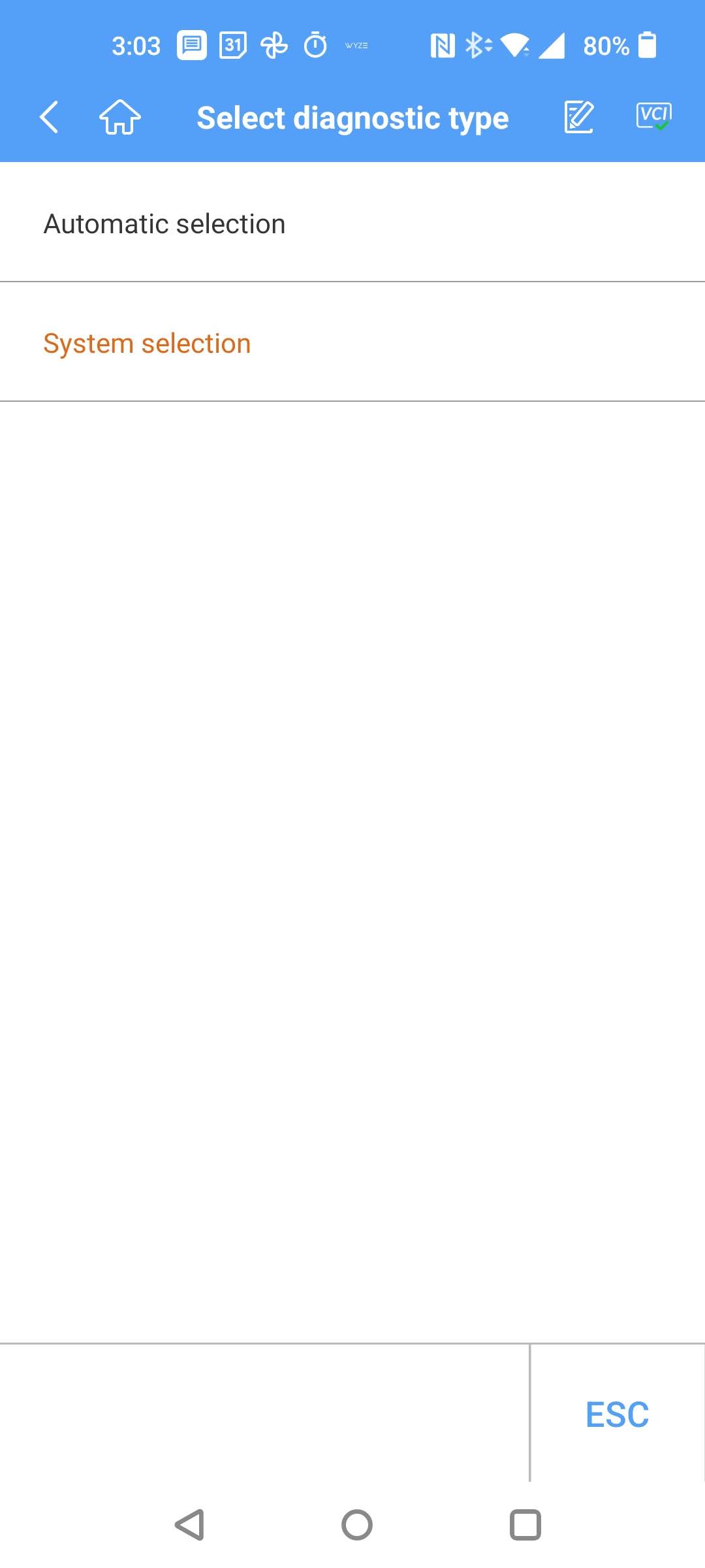
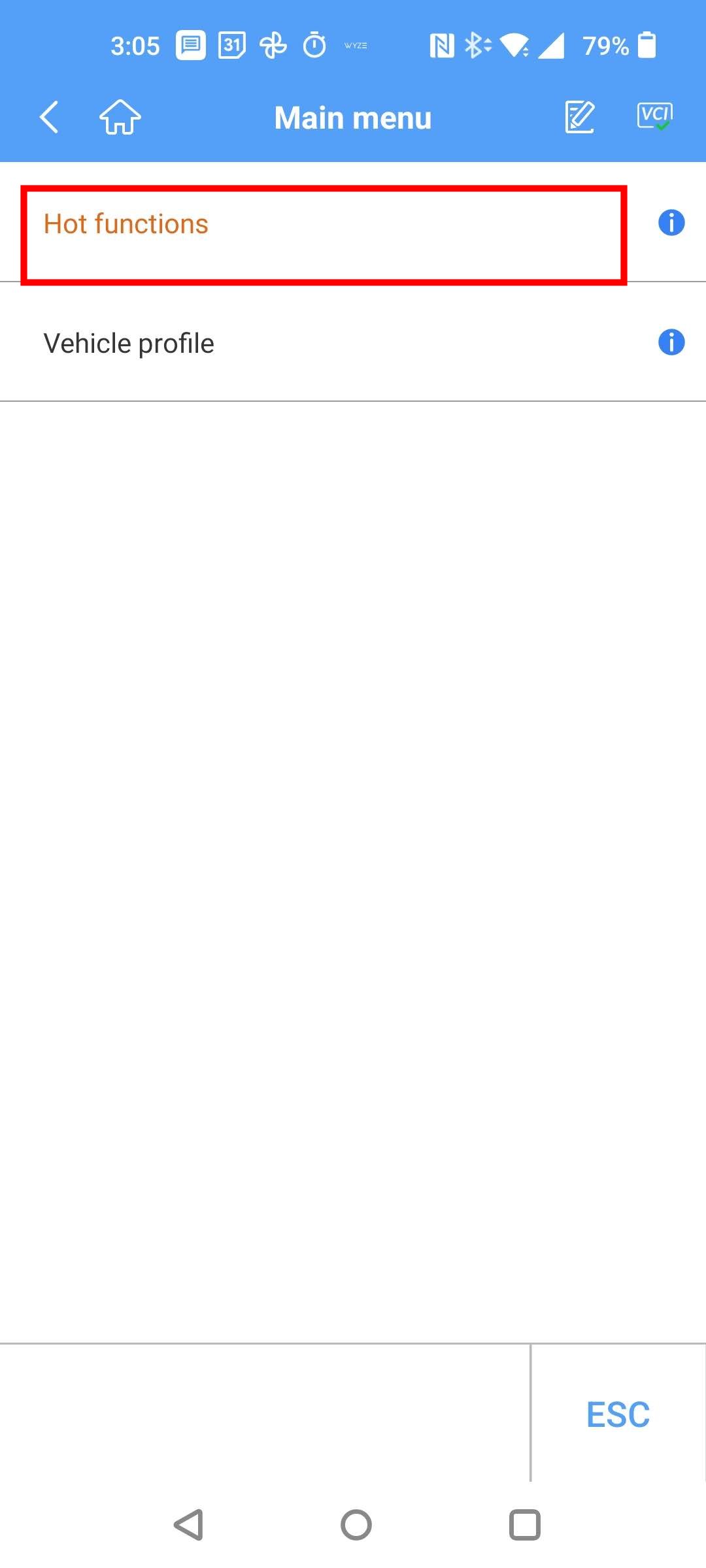
Next select Hot functions:
Tap One-push start:
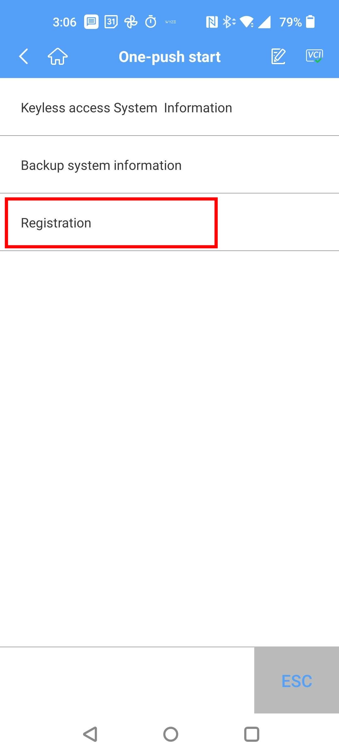
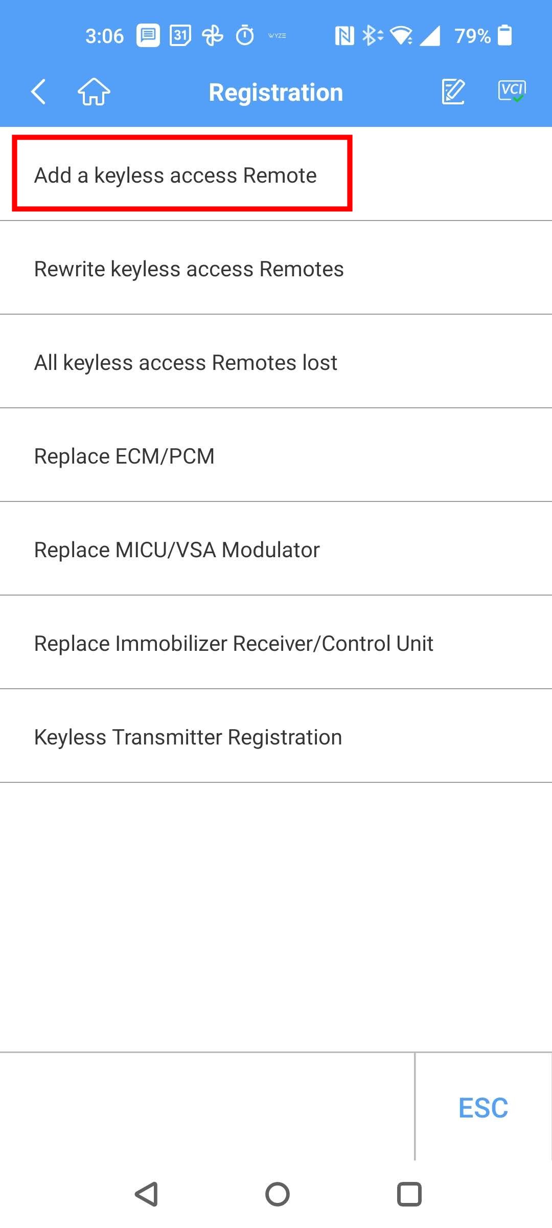
Tap Registration, which takes you to the functions for adding/removing fobs:
Select Add a keyless access Remote:
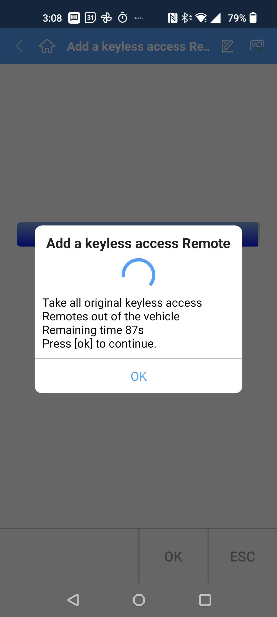
This launches you into the procedure for registering a new fob. Sorry, this is the part where I am missing some screens below. I can’t remember exactly, but it walks you through several steps.. pushing the car’s Start button w/ a working key fob in the vehicle, turning the car off, pushing the Start button w/ they fobs in and out of the car, etc. Just follow the prompts. I don’t remember the exact order. Below is one of the prompts:
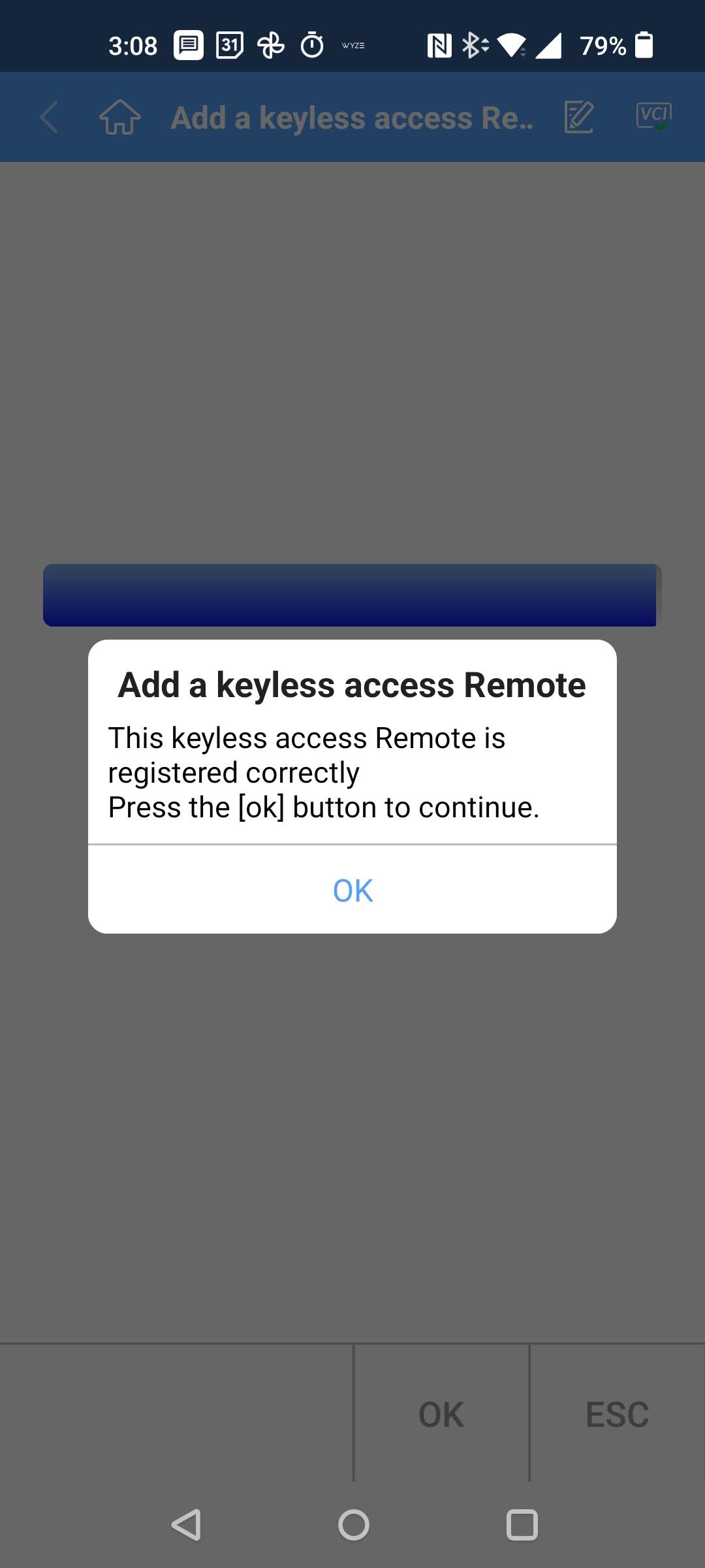
After you walk through all the steps, if you did everything correctly, you get this screen:
Now, the moment of truth! Try using your newly programmed fob to lock/unlock the doors, and start the car!
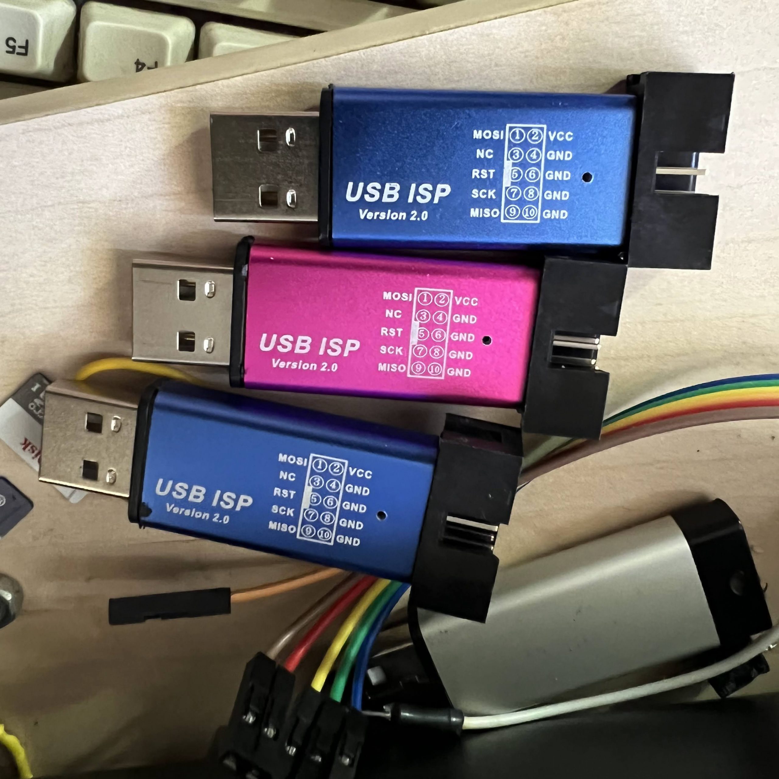
I recently ordered some USBasps from Amazon, which looked interesting, because unlike the typical USBasps, which are just bare PCBs, these had metal cases:
They are also common on AliExpress.
Unfortunately, when I plugged one into my computer, it detected as a USBHID device with VID=03EB and PID=C8B4, rather than as a USBasp. I tried overriding the USBHID driver on my Windows 10 machine, but that didn’t work.
Thankfully, after doing a bit of searching on the Internet, I found that others had encountered the same problem, and had found a solution. It seems that the firmware loaded into these things from the factory is proprietary, and require that you use the manufacturer’s janky software … it’s not AVRdude compatible!
Thankfully, the hardware is actually compatible w/ USBasp firmware with a minor tweak, and you just have to flash it with modified USBasp firmware.
I have a bunch of real USBasps, so I used a USBasp to convert the fakes into real USBasps! In order to program it, slide off the metal case. Next need to connect a jumper across the two holes labeled –> UP <–. The jumper enables programming of the onboard ATmega88V. Then plug it into your other USBasp or other ISP programmer, using the 10-pin ICSP cable:
So where do you get the special firmware? GreenPhotons has graciously compiled a modified firmware for us. Next use AVRdude to program the USBasp firmware into our target:
You can use any ISP you already have, if you don’t have another USBasp. Just substitute the programmer in the -c parameter (e.g. -cusbtiny for a USBtiny). If you don’t have another ISP programmer, you can use an Arduino. This guy shows you how, as well as another way to get firmware.
If you get the following error, then your USBHID ISP has an ATmega88P instead of an ATmega88V
D:\hacking\arduino\USBasp\convert_usbhid>avrdude -cusbasp -pm88  -Uflash:w:20161227_mega88_usbasp.hex

avrdude: AVR device initialized and ready to accept instructions

Reading | ################################################## | 100% 0.02s

avrdude: Device signature = 0x1e930f
avrdude: Expected signature for ATMEGA88 is 1E 93 0A
         Double check chip, or use -F to override this check.
Just substitute -pm88p for -pm88 in the avrdude command line:
I have a Korg N1 synth, which I’ve had for many years. Recently, it started having strange symptoms: after warming up for several minutes, the audio would get slightly distorted, but only on certain notes. The effect was rather subtle, but enough to drive my wife absolutely bonkers.
First, I tried to isolate the problem. I tried headphones, connected to the jack on the front left of the keyboard, to rule out my amp. The distortion didn’t go away. Next, I compared the output from the rear audio jack to the headphone, and the distortion sounded exactly the same.
I first tried google, to find out if this was a common problem. It turns out that the N1 wasn’t particularly popular, so there wasn’t much info on problems/repairs, not even teardown photos.
OK, time to take it apart. I first took the screws off the wood side panels, and removed the metal cover on the front, under the keys. Totally the wrong approach. Upon looking at it more closely, I noticed that the bottom is hinged. All you have to do is take out the big philips screws, and then it flips open.
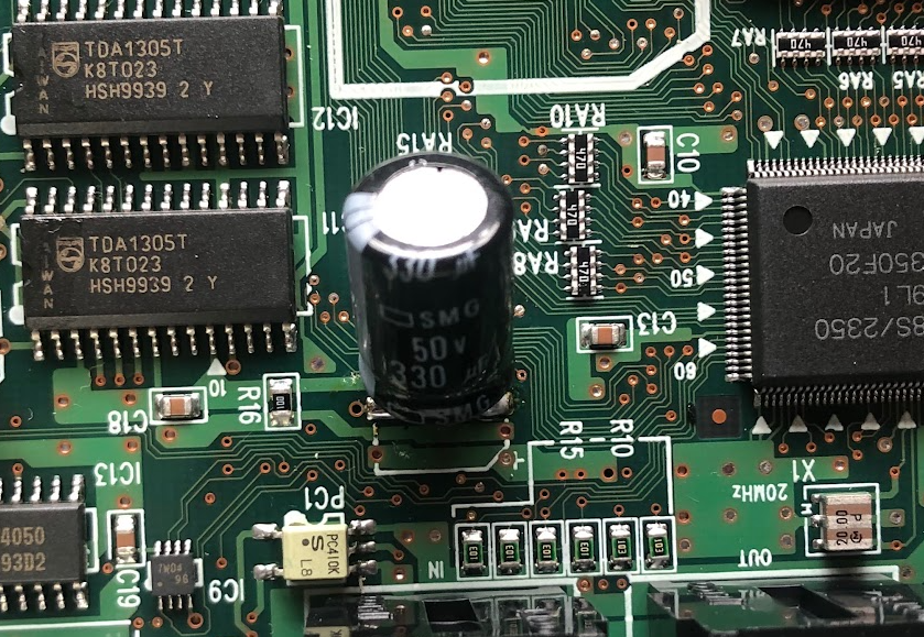
Once I had access to the inside, I looked/smelled for any burned/damaged parts, loose wires, and bad solder joints. Nothing looked amiss. Another thing that’s a common failure point in aged electronics is aged electrolytic capacitors. They often go bad. The most obvious clue is that the tops will bulge up or burst open. I couldn’t see any that looked obviously bad, so I started touching the tops of the SMT electrolytics to feel if any of them were bulging. I found one that had an almost imperceptible bulge on top. It’s in the photo below:
The bulge is so slight, you can’t even see it in the photo above, but I could just barely feel it. Surely, this wasn’t the bad component? Since I couldn’t find anything else wrong, I decided to try replacing it.
At first, I was going to try to remove it w/ a hot air gun, but it’s so big, and close to other components, that I decided that was too risky. I searched the Internet again, and someone suggested just cutting the can in half w/ some cutters, and then yanking out the rest. It turned out to be an easy and safe method. And, it left two short protruding wires attached to the circuit board, which made it easier to solder in a new cap. (Sorry, I should have taken photos, but forgot).
Anyway, here’s what it looks like w/ the replacement soldered in place:
I was extremely skeptical that replacing this capacitor would fix the distortion, but amazingly, when I turned it on, and left it for an hour, the problem was gone! It’s been over a month now, and there is no more distortion, no matter how long it’s turned on. Amazing.
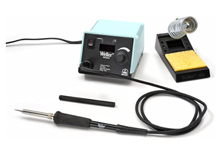
Over the past couple of years,my Weller WESD51 soldering station had been getting progressively flaky. Sometimes, I would have to fiddle with it for a while to get it to heat up. Finally, one day, it just stopped heating altogether. I had trouble finding info on how to fix it, mainly because I couldn’t even find the pinouts for the soldering pencil attachment jack.
Finally, I hit the jackpot last week. I found this thread in AllAboutCircuits discussing a similar model, the WES51. The main difference between the WESD51 and the WES51 is that the WESD51 has a digital temperature display, while the WES51 only has a status LED. While the thread didn’t tell me how to fix it, I found the user/troubleshooting manuals attached! I have linked the manuals at the bottom of this post. Unfortunately, following the troubleshooting guide didn’t help me find the problem, because everything checked out OK.
Then I found this guy’s YouTube video on fixing a WES51 that wouldn’t heat up. As I suspected, the PCB’s in the two different models is very similar. In the guy’s video, he fixes it by replacing a 2.2uF capacitor that’s connected to the heater’s power transistor. I checked the corresponding capacitor in my WESD51, and sure enough it was bad. I found a in my junk parts bin to swap in and bingo, my WESD51 is working again! The step by step procedure is below.
Step 1: Open the case
First, you need to open up the case. Pop out the rubber feet at the bottom of the controller case. Underneath are philips screws.
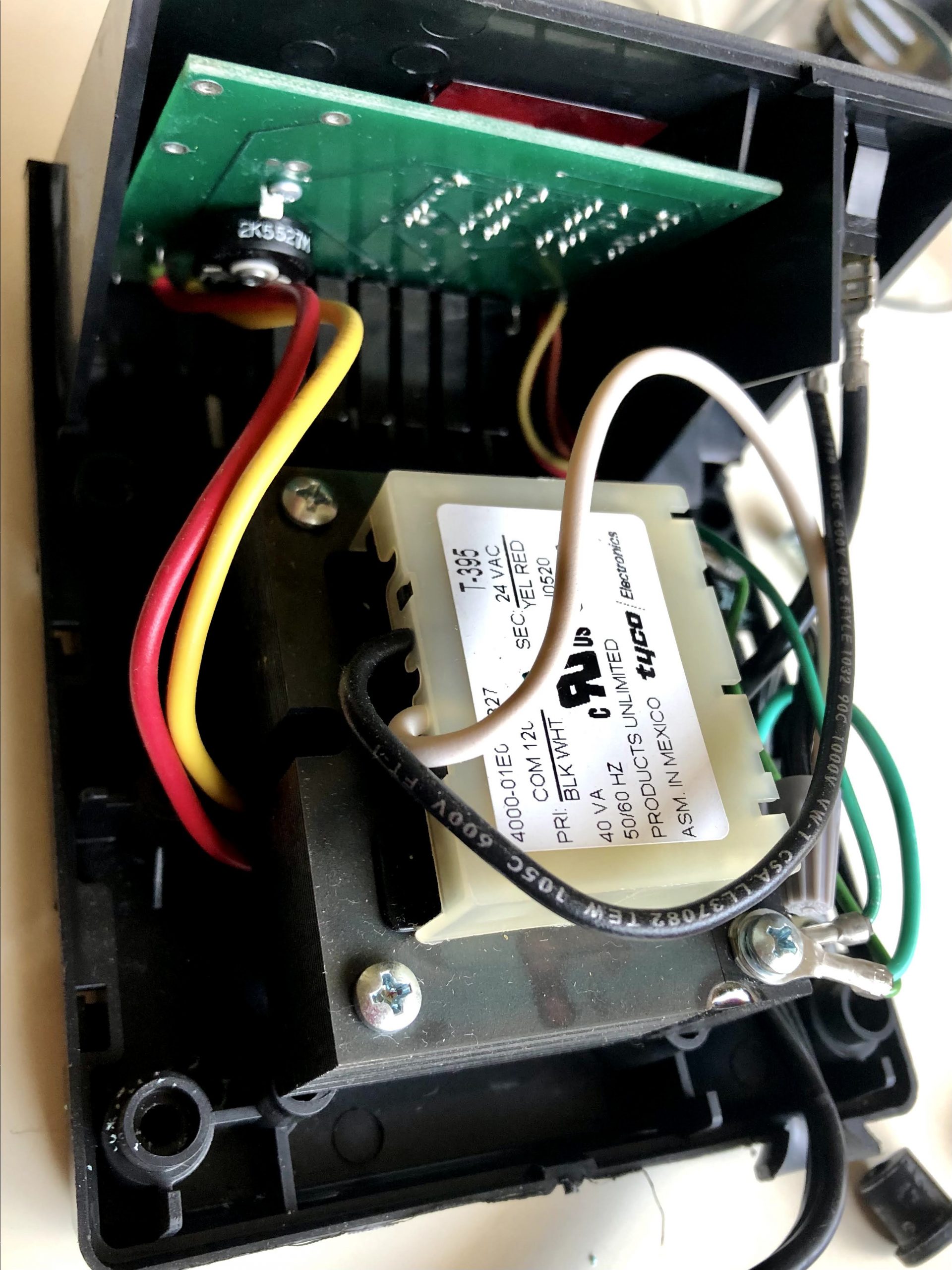
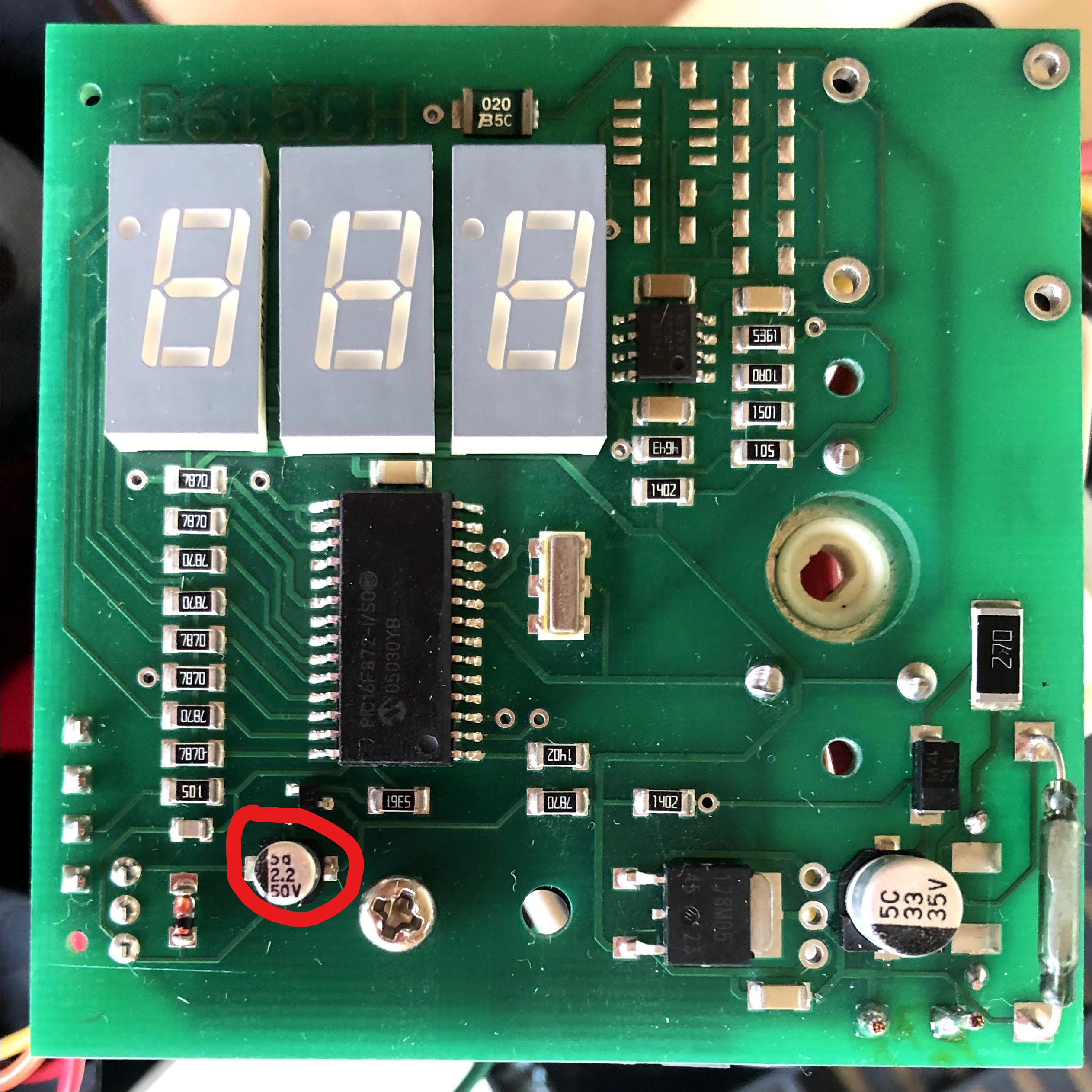
After you remove all four of them, the blue upper body easily separates. Here’s what’s inside:
Step 2: Remove PCB
Separate the green PCB from the casing. You don’t have to remove the temperature adjustment knob from the faceplate. Locate the 2.2uF/50V capacitor. It’s circled in red in the photo below:
Step 3: Remove existing 2.2uF capacitor
Carefully desolder the capacitor circled in red above. If you don’t have a capacitance meter, just try swapping in a new part, and see if it fixes the problem.
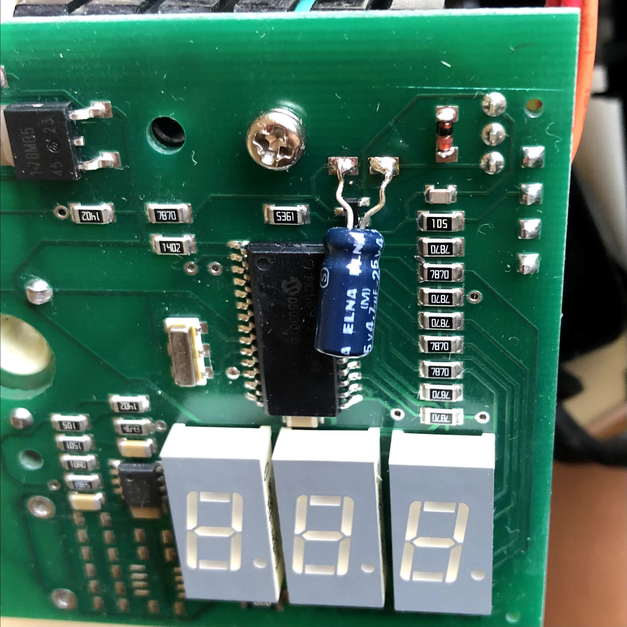
Step 4: Solder in a replacement capacitor
Make sure to pay attention to the polarity of the electrolytic capacitor… the negative terminal faces the line of SMT resistors on the right of the photo above. I didn’t have an exact replacement in my parts bin, so I just used a 4.7uF/25V part… the circuit voltage is 24V, so 25V isn’t much headroom, but it’s easy to replace it again if it fails in the future. Before putting everything back together, I fired it up, and it was heating again!
Commercial mine machines are quite expensive, and often inflexible, containing only a few canned programs. In this series, I will show how to build an infinitely reconfigurable photic-stim mind machine on the cheap. Rather than build an oscillator circuit, we will drive our mind machine with computer-generated waveforms via an audio player. You can use your favorite audio playing program on your computer, or a portable MP3 player.
UNDER CONSTRUCTION: I still have a ways to go w/ filling in details, but I thought I would at least throw up the article first, since it might take me forever. Please pardon the omissions.
Photic-stim goggles cost typically more than $50, but they’re typically built with only <$1 worth of LED’s, and some cheapo ski-type sunglasses.
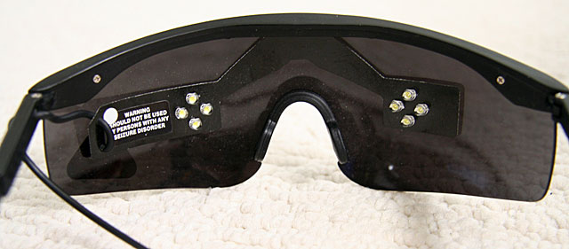
Below are the lightframes which came with my Sirius AVS machine, which I purchased from MindModulations.com.
Note how they are just as I described above, a cheap pair of ski-type sunglasses, with 8 LED’s wired into a sheet of black plastic. The plastic is attached to the sunglasses with double stick foam tape.
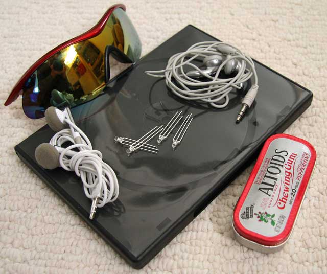
Below are the materials we need for our project:
Bill of Materials (BOM)
Ski goggle style sunglasses. I purchased this pair for under $10
Stereo wiring with 1/8 in phone plug. A cheap pair of earbuds from a local 99 Cents Only Store is perfect for cannibalizing.
Thin, flexible black plastic sheeting. A spare DVD case courtesy of junk mail from AOL will do fine.
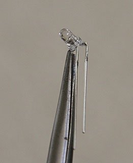
LED’s. The type and number of LED’s is up to your own taste. Since my design uses the black plastic sheet insert, I picked 3mm LED’s… they need to be small enough that they won’t bump into your eyes when you’re wearing the goggles. If you want to drill directly into the goggle lenses and eschew the plastic sheet, you can use bigger LED’s. I bought my LED’s from UniqueLEDS.com. They have an extensive selection, and list detailed specs for the LED’s, including brightness. SUPERBRIGHT
Not pictured is a few inches worth of hookup wire. I had some kynar-insulated 40AWG wire wrap wire laying around, which was perfect, due to its extremly thin diameter.
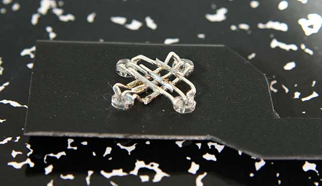
How many LED’s you use is up to you, but the minimum is two, one for each eye. I decided to use 8 … 4 for each eye. Also, I used two different colors, green and blue, on alternating diagonals. Note that my LED’s have 3 leads instead of the usual two. This is because I had a wild idea of using bicolor LED’s so that I could get different color combinations, but I’m not very sensitive to the colors, so I decided to hook them up like one-color LED’s. There are various recommendations on the web for color selection. Personally, I like the bright white LED’s that my Sirius frames used, but I decided to experiment with colors on this set.
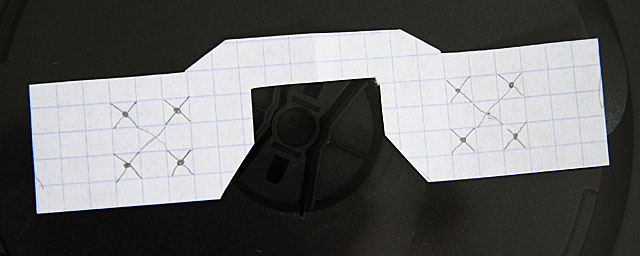
First, cut the black plastic which will support your LED’s. Ask I said above, you can skip this step, and drill directly into the lenses, but it will look a lot uglier, since the wiring will be exposed in the front. Also, the drilling method doesn’t let you easily reconfigure the frames if you change your mind about the layout. I used graph paper to make a paper template for my LED layout:
You should lay out the LED’s so that they’re fairly well-centered over your eyes. If you space them out a bit, it will allow for inaccuracy, and eye movement. Note that my layout is rotated 45 degrees with respect to the layout used by the Sirius. My DVD case was soft enough that I could just use scissors to cut out the template, but you may need to use an X-acto knife.You can use a drill for the holes, but I spun an X-acto knife around, instead, and slowly increased the size of the holes until I had a tight fit. (BTW, for the curious, those are not my hands in the photo).
I misaligned one of the holes a bit, as will be apparent in later photos, but it works fine, even though it’s a bit ugly.
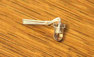
Since we want to keep the LED’s far enough away that they don’t hit your eyes, we need to bend the leads as tightly as possible. I used a pair of needle-nosed pliers, but if you’re careful, you can just use your fingers on the edge of your desk:
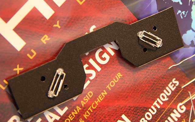
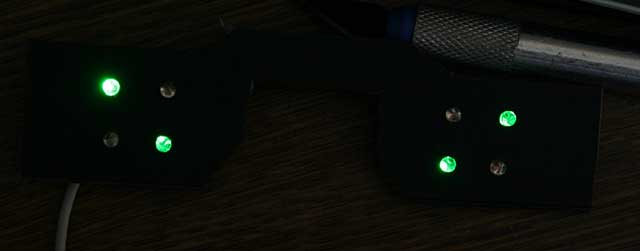
Here’s what they look like when they’re done. Since my layout uses alternating colors on the diagonals, I first bent two of the green LED’s. Then, I bent another pair of green LED’s in the opposite direction. The opposite polarity of the bending is important, because the LED’s are hooked up in parallel. Here’s what they look like before I cut the leads:
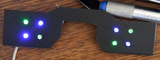
Now, the wiring and layout of the leads will vary considerably, depending on how you want your LED’s to behave. The lightframes I built behave very differently from the Sirius lightframes, which utilize the industry standard wiring. In the Sirius setup, all 4 LED’s on a particular side light up synchronously. The left side responds to the left channel, and the right side responds to the right channel, so the two sides can be controlled independently. This is an example of how they can blink:
My design mimics the IC/D setting of TC-Softworks lightframes, hooks up each pair of diagonals together. The greens respond to the right channel, and the blues respond to the left channel. Therefore, both eyes are always lit, but the intensity and color can vary.
You can use your imagination to come up with your own unique design.
If you are building your goggles to work with a particular mind machine, be aware that there is another variation in the wiring, which affects the compatibility. All of the schematics I have shown up to now have used Common Ground (CG) wiring, where the cathodes (grounds) are all tied together. Some machines, such as my Sirius, use Common Power (CP) wiring, where the anodes (power) are tied together. Before wiring up your goggles, make sure you know if you need CG or CP wiring. As it stands, the goggles I built are incompatible w/ my Sirius.
You must also be aware that which polarity you choose will affect the polarity of the signals that you use to light up your goggles. CG goggles light up when the signal is positive, and CP goggles light up when the signal is negative. Thus, if we use the following signal, CG goggles would light up in the first half of the cycle, and turn off in the second half, where the signal goes negative.
On the other hand, CP goggles will do the opposite, and be dark in the 1st half cycle, then light up in the 2nd half cycle.
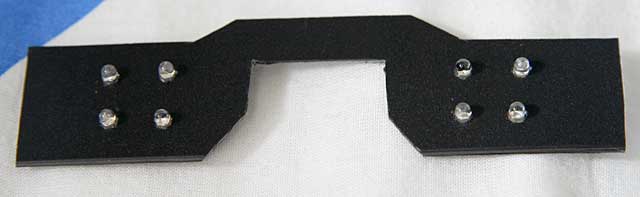
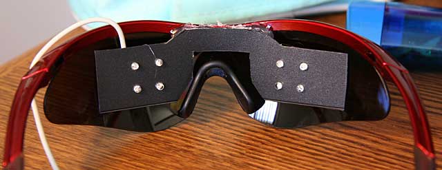
Next, I fit them into the plastic, and soldered the wires:
Be careful to solder as quickly as possible, and not to use a high-wattage iron, because LED’s are semiconductors, and can easily be destroyed by overheating.
The inner pairs of LED’s have to be bent a bit differently, so that the leads don’t touch and short out w/ the outer pair of LED’s.
In my case, they were the blue LED’s. Note that the LED’s w/ the extra bend actually go on the inside, so I had to take the first pairs out first. Here’s what they look like up close. Although the inner and outer wires look like they’re touching, there’s a tiny clearance. Here’s what it looks from the other side:
I know, I know, the holes are a bit off, but it’s accurate enough.
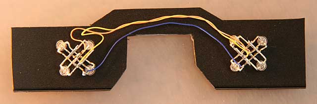
Next, I connected up the wiring. Since my goggles are wired up for CG, the center leads (the cathodes) of all of the LED’s are wired together. The anodes of each color are all wired together. NEEDS PIC OF TRS WIRING HERE
20221212: Tapo Users, update from reader Roman below: The Tapo app on Android now has a software/firmware update that lets you reset the energy consumption from the app. Hopefully, iOS is the same.
20220914: Note: If you have an Apple device, you no longer have to use my laborious procedure documented below. The Watt for Smart Devices app can reset the energy and usage stats of both Kasa and Tapo devices.
WARNING: This method DOES NOT work the Tapo devices. They use an entirely different API. I wrote some code to try sending reset_energy_usage to a Tapo plug, but it rejected the command. If anyone knows the command to reset the energy usage of a Tapo, please leave a message below. Also, I might be able to find the correct command if someone can send me a firmware file for a Tapo plug with energy monitoring.
I recently acquired a few TP-Link Kasa KP115 smart plugs with energy metering. It was a bit disappointing to find that they barely show any data. There are no graphs, no voltage or current, just instantaneous power and summary energy stats and runtime:
I wanted to find the daily energy consumption of various appliances, so I needed a way to reset the energy counter to zero. Believe it or not, TP-Link doesn’t provide a way to reset the energy. TP-Link support says that you have to delete the plug from Kasa, factory reset, and then add it back to Kasa.
The most ridiculous part is, the smart plugs actually have a command to reset the energy without resetting the whole device! They’re just too lazy to add it to their app!
I found a github repo with a list of the commands available in the TP-Link protocol. It turns out that there’s a command to reset the energy monitor!
Erase All EMeter Statistics
{"emeter":{"erase_emeter_stat":null}}
The repo contains a Python3 script that can query the energy stats, but it doesn’t have an option to send the emeter reset command. Fortunately, it has a command line option to send an arbitrary JSON command to the plug. I tried sending the above to my KP115, and the energy meter was instantly reset to 0!
Next you need to know the IP address of the smart plug you want to reset. If you don’t know how to find it from your WiFi router, you can scan for it with an IP scanner, such as Fing. Look for a device named KP115 (or HS110).
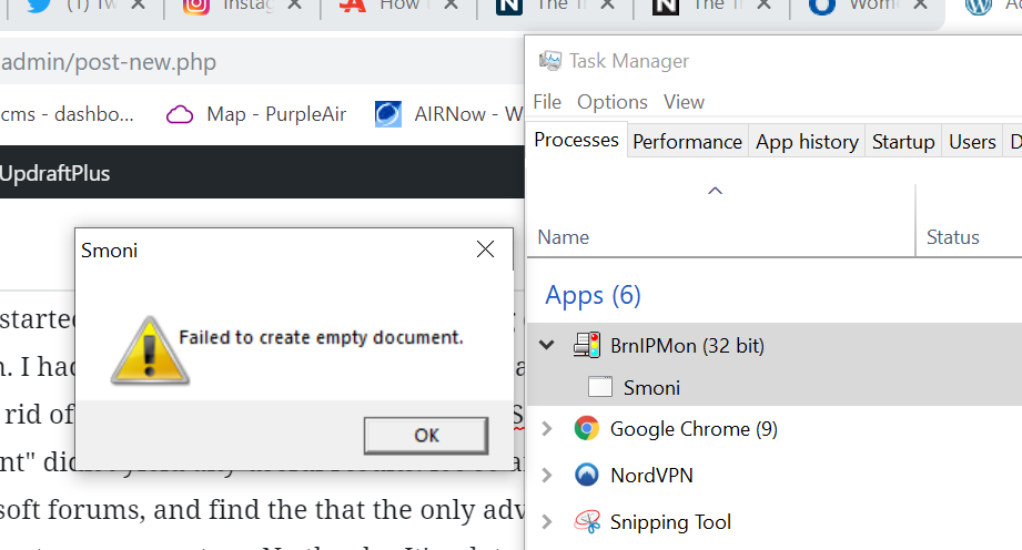
At some point in the past several months, probably after a Windows 10 update, my PC started to display a cryptic and annoying dialog box every time I logged in. I started wondering if somehow, a virus had gotten into my computer. I hadn’t spent the time to figure out what it was causing it, and how to get rid of it, until today. A google search of “Smoni Failed to create empty document” didn’t yield any useful results. It’s so annoying to go through Microsoft forums, and find the that the only advice they can give you is reset or restore your system. No thanks. It’s a lot easier to spend a little time troubleshooting on my own, than spending hours backing up and reloading all my programs and files.
I pulled up the Task Manager, scanned the running process list, and quickly found the culprit:
Aha! What’s this BrnlPMon process? Simply right click on BrnlPMon, and select Open File Location from the menu:
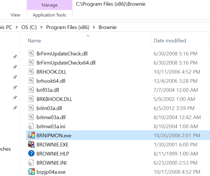
Windows then pops up a File Explorer window, with the offending file highlighted:
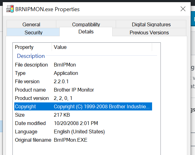
Hmm.. so what’s BRNIPMON.exe? Right click the file, and select Properties from the context menu. Select the Details tab on the resultant pop-up window:
Bingo! It’s Brother IP Monitor, which I figured out is monitoring software for my Brother WiFi connected laser printer. Something in my recent Windows 10 updates (probably the new Creator’s Edition), caused an incompatibility, which triggers this stupid error dialog.
At this point, I could just uninstall it or delete the files, but since I now know that it isn’t malicious, I’ll just leave it for now, and look for a software update when I have time, and see if that fixes the issue.
Over the years, it has occasionally had issues with low water pressure. I’ve had to take it apart several times, and have narrowed it down to a couple of common problems. In this article, I’ll explain how to quickly diagnose and fix it, so you don’t have to spend hours on it like I did.
Diagnosis
First we need to figure out where the problem lies.
Are both the hot and cold water flowing slowly? If so, the problem is likely in the spray head assembly. See Spray Head section below.
Is only one side flowing slowly? If only hot or cold is flowing slowly, and the other side is flowing fine, then the problem is likely that an inlet screen is clogged. See Clogged Inlet Screen section below.
Spray Head
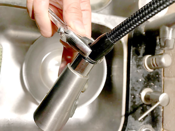
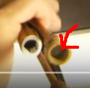
Pull out the spray head, and use a crescent wrench to hold the end still while you unscrew the spray head from the faucet:
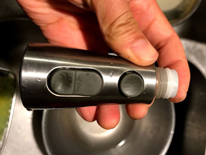
Turn on the water full blast. If it flows out of the hose strongly, then your spray head is definitely the culprit. With dry fingers, pull the black plastic buttons off the spray head.
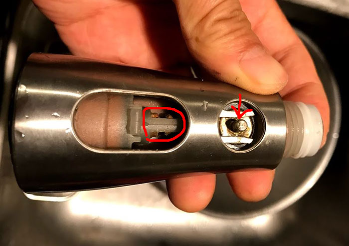
grab the pin located by the red arrow in the photo above with a pair of needle nose pliers. Turn it, and push it in and out until it moves smoothly
use a small screwdriver inserted into the slot in the metal piece denoted by the red circle in the photo above, and slide the metal piece to & fro until it moves smoothly
(optional) if you have silicone spray, spray it into the areas where the plastic and metal interface, and again move the metal pieces to & fro until they move even more smoothly
At this point, you can reassemble and test it out. Most likely, the problem will be fixed already. However, as long as you have it taken apart, you might as well clean off the calcium deposits. There are two places where calcium builds up: 1) the inlet screen
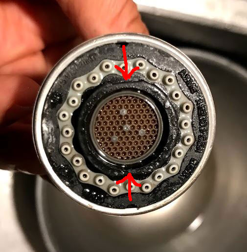
and 2) the aerator and jets
The entire black plastic face containing the aerator should be removable if you grab the flat sides of the inner black core around the aerator (see red arrows in photo above) with a wrench and unscrew it. Unfortunately, mine was glued on by serious calcium deposits (in the photo above, I’ve already cleaned off the calcium but it was still stuck). If you can unscrew the black plastic face assembly, you can disassemble and clean the aerator more thoroughly. Since mine was stuck, I simply soaked both ends of the spray head in hot vinegar, and then used a brush to rub off the remaining calcium deposits. If the gray jet holes are not clean, you can also insert a round toothpick into each hole, and rotate it to clean it out. Reinstall the spray head and test. The water should be flowing strongly now. If so, you are done.
Clogged Inlet Screen
If only the hot or cold side (usually only the hot side) flows slowly, while the other side flows strongly, the inlet screen on the clogged side is probably clogged up with calcium deposits. Go under the sink, and with two wrenches, unscrew and detach the inlet hose from the faucet on the side that’s clogged.
sorry for the horrible photo. The red arrow in the photo above points to the inlet screen. It’s not removable, so you have to clean it in place. Mine was completely gunked up with calcium deposits that had broken loose from my old water heater. I used q-tips soaked in vinegar, followed by scraping with a small screwdriver to clean the screen. Reattach the inlet hose and test. If the water’s flowing strongly again, you’re done!