LeafCAN v2 Firmware in Alpha Test

I have been working on v2 of the LeafCAN firmware, which adds a whole slew of new screens, selectable via a rotary encoder.  The rotary encoder is connected to the AD0/1/2 pins on the expansion header of the LeafCAN V2 hardware.  The code is currently in alpha testing, and is available in the development branch of the LeafCAN github repository.  Be aware that the development branch is for my bleeding edge code, and at any time, the code there may be broken, as I continually checkpoint my code.  I will move it to the master branch when it’s ready to be released.

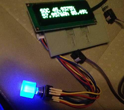
While I was developing the LeafCAN v2 firmware, I received a pleasant surprise in the mail from Barbouri (GregC) of the MyNissanLeaf forum.  He designed a PCB with 16×2 OLED display + RGB Led Rotary Encoder support,

v2o

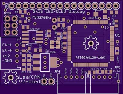
and sent me a completely assembled and tested rig.  I immediately added support for this new hardware variant into my working LeafCAN v2 firmware code.  The RGB knob is cool:

encoderled

but I am still pondering how best to use it. Currently, I have it blue when the car is idle, red when it’s consuming power, and green during regen.
Below is an overview of LeafCAN v2Alpha3. The various screens are selected by rotating the encoder knob. Some of the screens have different modes, selected via a press of the encoder knob. The first screen is the familiar info screen from LeafCAN v1.3:

mainscreen

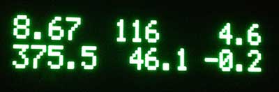
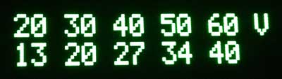
The top line from left to right is: kWh remaining/gids/fixed fuel bars, and the bottom line is: pack voltage/SOC%/instantaneous kW. The next screen is an idea lifted from Turbo3’s WattsLeft, the DTE (distance to event) screen:

dtel

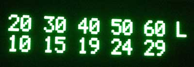
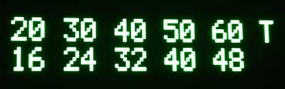
The top line shows various miles/kWh values, 2.0/3.0/4.0/5.0/6.0, and bottom line shows the distance in miles to the event, in this case, Low Battery.  Pressing the encoder button switches it to miles until Very Low Battery:

dtev

and pressing the button a third time shows miles until Turtle:

dtet

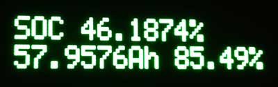
Thanks to a breakthrough in active can sampling, spearheaded by GregH and TickTock, I was able to implement the following new screens. The first one has on the top line, High Precision State of Charge (SOC)%.  The bottom line shows State of Charge (Ah), and possibly a Battery Health %.

soccap

The next screen shows the 4 battery pack temperature sensors:

batttemp

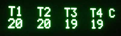
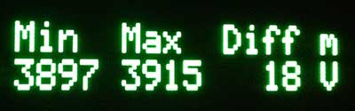
The units are selectable between Celcius and Fahrenheit with a press of the button. Finally, the last screen shows the minimum and maximum cell-pair voltages in mV, as well as their difference:

cellvolt

When an OLED is installed, the display now blanks after 5 sec of inactivity on the CAN bus. Pressing and holding the knob for a second wakes the display up for 5 sec.  When an LCD is installed, the press/hold turns on the backlight for 5 sec, instead.

I will be working towards finishing LeafCAN v2.0 in the coming weeks, and will announce its release here.

Barbouri and I are also collaborating on a dual-CAN bus version of the LeafCAN hardware, which will be able to monitor the Car-CAN as well as the EV-CAN on the Nissan Leaf. This will open up access to various information which is accessible only via the Car-CAN, such as friction brake actuation, steering angle, etc.

I would also like to point out that GregH has yet another cool Leaf CAN bus dash display in the works (only $80) that is worth checking out. Also, TickTock and garygid are working on the very fancy dual-touchscreen open-source CANary Project. Turbo3 has also figured out how to extract data from the Leaf Car-CAN using a cheap ELM-327 clone dongle and an Android phone. There is currently a flurry of CAN bus hacking on the Leaf.

AT90CAN Support for Arduino 1.0+

I have adapted the Arduino AT90CANxx support to work with Arduino 1.0+. Also, I have moved the code to github, so that it will be easier to update.  Note that the Arduino 1.0+ support is currently only alpha quality.  I have compiled a few sketches, but I also have found some which currently can’t compile.

You can always download the latest version at https://github.com/lincomatic/AT90CAN

It is easiest to download the whole repository as a zip file: https://github.com/lincomatic/AT90CAN/zipball/master

Follow the instructions in the README file.  For more information, see the post linked below.

Related Post: AVR CAN Bus Project – Step 1: Programming AT90CAN128 with Arduino

LeafCAN Hardware V2

Chris H built and sent me a revised board for LeafCAN. The V2 board puts all of the components on the back of the board, instead of facing the LCD.  By also eliminating all of the header pins (except for the ones used to connect the LCD), the assembly becomes considerably thinner than V1:

Below are my V2 and V1 meters side-by-side.  The V2 meter is on the left:

The new circuit allows software control of the backlight, so I changed the firmware to turn off the backlight 5 seconds after CAN bus activity stops, and turn it back on when the activity resumes.

I also added a new feature, which I call “fixed fuel bars.” Recently, I noticed that the 12-segment fuel bar display in the Leaf’s dash is misleading and inconsistent. Even as your battery degrades, it always displays 12 bars at 100% charge, regardless of how much energy your battery can store. Over the course of 10K miles and 1 year of driving, my range has been dropping. Lately, I’ve been caught off guard, almost running down to turtle on 2 occasions, on a 66 mile drive that used to be easy. My SOC at 100% has dropped from 270 to 255 (I never got 281, even when the car was new). Another thing is, the car often only has the range with 3 bars remaining that I used to get with 2 bars remaining. So, I decided to make a new fuel display, which directly links the SOC and “fuel.”  On my fuel scale, 13 = 281 gids, and the transition from 0 -> 1 is at 24 gids, which corresponds to Very Low Battery.  The number is displayed with 1 decimal point.  I put the zero point at Very Low Battery, because when the charge gets this low, we really need more precision, and should be using raw SOC values.  Unlike the fuel bar display in the dash, the first bar contains as much energy as the rest.

I find it more convenient to use this new fuel gauge than SOC %, because I can easily do the calculations in my head while driving.  When driving, I’ll count the number of miles for it to drop by 1, and then multiply it by the remaining count.  For example, saw the car goes 8.3 miles when the “fuel” drops from 11.1->10.1.” Then I estimate that I can comfortably drive 80 miles given the current driving conditions.

Worst case for me is about 5 miles per fuel point, so when I want a conservative estimate of range, and I know I’m not going to be climbing any long, steep hills, I can just multiply the fuel number * 5 to estimate range.

In the photo below, you can see I’ve rounded the corners on the new case, and the slimmer design looks nicer.  Also, I’ve switched to a 4-conductor white telephone cable, which is slimmer, and thin enough to squeeze in the gap between the left dash & the body.  I’m able to use only 4 conductors, because this build is hardcoded to use only the EV bus, so the only wires I need are power/ground/CANH/CANL.

The top line displays:  remaining pack KWh/SOC in gids/remaining fuel

The bottom line displays: pack voltage/instantaneous amps/instantaneous power draw KW (pack voltage * amps / 1000).


As usual, the latest code is available on github, and you are welcome to modify the display code to suit your own tastes.

AVR CAN Bus Project – Step 1: Programming AT90CAN128 with Arduino

Last month, I bought a Nissan Leaf EV.  It’s pretty cool driving around in an all-electric car.  Luckily, there’s a great forum called MyNissanLeaf, where Leaf owners can learn a lot, and share information.  I’m currently collaborating with one of the forum members to design and build a Level 2 EVSE.  I will document that project on this blog at a later date.  Having a serious case of project ADHD, I discovered that forum members had set about hacking the Leaf’s CAN buses, and couldn’t resist joining the fray.

Being most familiar with ATmel AVR microcontrollers and Arduino, I decided to use that platform for this project.  ATmel has a subtype of the AVR with CAN bus capabilities, the AT90CANxxx.  I found an interesting development board containing an AT90CAN128 and headers for access to all the pins on the MCU.  I ordered one from Sparkfun for $29.95.  They also sell another board, the AVR-CAN, but it contains things that I don’t need, such as an RS-232 interface, and can be programmed only via JTAG – I only have a USBtinyISP, which is an ICSP programmer.  Unlike the AVR-CAN, the AT90CAN128 Header Board doesn’t contain a CAN Bus transceiver.  I decided to go with the Microchip MCP2551, since that’s what the AVR-CAN uses.

The AT90CAN128 header board is from Olimex, and comes in a cute little box:

Here’s a closeup of the front:

and the back:

I decided to try to get this board working with Arduino, since it’s a lot easier to set up than WinAVR.  The first problem to solve is how to adapt the Arduino IDE to work with the AT90CAN128 and my USBtinyISP.  After much Googling, I found SuperCow had already done the dirty work and posted it to the Arduino forum.  He packaged the core files, bootloader, and a couple of examples into a handy zip file (which has since been taken offline). Since he used an unknown JTAG programmer, I had to adapt his files to work with the USBtinyISP and JTAG ICE mk1.  Also, I modified them to work with Arduino 1.x+.

You can download the latest version from github: https://github.com/lincomatic/AT90CAN  To install it, simply unzip the atcan90 directory into <your arduino directory>/hardware/at90can.  Next time you restart Arduino, you can select it from Tools->Board->[usbtinyisp]AT90CAN128.

If you have a JTAG ICE mk1 programmer instead, select [JTAG ICE mk1]AT90CAN128.

I connected up my USBtinyISP via the 10-pin ICSP header, burned the Blink sketch, hooked up an LED, and bingo!  It’s working flawlessly.

In at90can/cores/at90can, I found can_lib.h and can_lib.cpp, which appear to be all we need to interface to the CAN bus.  Since I currently know ZERO about CAN bus, I have a lot of reading to do before I can commence programming.  SuperCow’s original zip file contains a couple of rudimentary examples.

Before I start programming, I need to build a little interface board containing the MCP2551 CAN bus transceiver, which should arrive next week.  I already have an OBD-II cable to tap into the Leaf CAN bus via the OBD-II connector.  Currently, obdcables.com is having a special on the 9-ft model.


Downloads:  https://github.com/lincomatic/AT90CAN

Next: AVR CAN Bus Project – Step 2: Programming Low Fuse