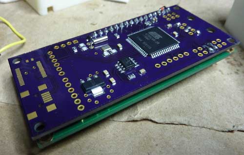
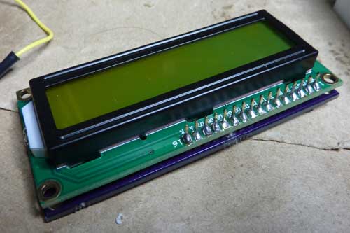
Chris H built and sent me a revised board for LeafCAN. The V2 board puts all of the components on the back of the board, instead of facing the LCD. By also eliminating all of the header pins (except for the ones used to connect the LCD), the assembly becomes considerably thinner than V1:
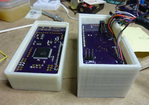
Below are my V2 and V1 meters side-by-side. The V2 meter is on the left:
The new circuit allows software control of the backlight, so I changed the firmware to turn off the backlight 5 seconds after CAN bus activity stops, and turn it back on when the activity resumes.
I also added a new feature, which I call “fixed fuel bars.” Recently, I noticed that the 12-segment fuel bar display in the Leaf’s dash is misleading and inconsistent. Even as your battery degrades, it always displays 12 bars at 100% charge, regardless of how much energy your battery can store. Over the course of 10K miles and 1 year of driving, my range has been dropping. Lately, I’ve been caught off guard, almost running down to turtle on 2 occasions, on a 66 mile drive that used to be easy. My SOC at 100% has dropped from 270 to 255 (I never got 281, even when the car was new). Another thing is, the car often only has the range with 3 bars remaining that I used to get with 2 bars remaining. So, I decided to make a new fuel display, which directly links the SOC and “fuel.” On my fuel scale, 13 = 281 gids, and the transition from 0 -> 1 is at 24 gids, which corresponds to Very Low Battery. The number is displayed with 1 decimal point. I put the zero point at Very Low Battery, because when the charge gets this low, we really need more precision, and should be using raw SOC values. Unlike the fuel bar display in the dash, the first bar contains as much energy as the rest.
I find it more convenient to use this new fuel gauge than SOC %, because I can easily do the calculations in my head while driving. When driving, I’ll count the number of miles for it to drop by 1, and then multiply it by the remaining count. For example, saw the car goes 8.3 miles when the “fuel” drops from 11.1->10.1.” Then I estimate that I can comfortably drive 80 miles given the current driving conditions.
Worst case for me is about 5 miles per fuel point, so when I want a conservative estimate of range, and I know I’m not going to be climbing any long, steep hills, I can just multiply the fuel number * 5 to estimate range.
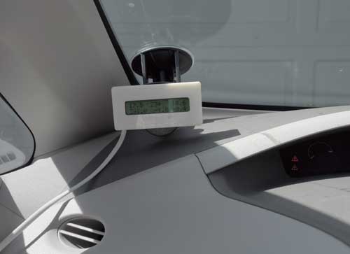
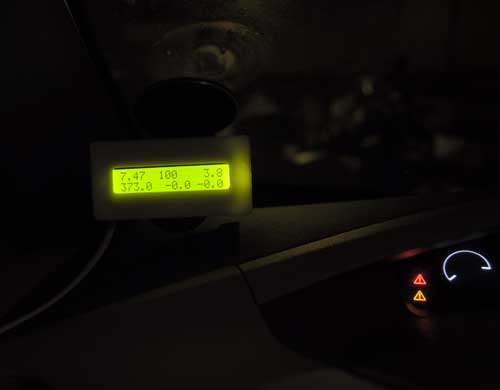
In the photo below, you can see I’ve rounded the corners on the new case, and the slimmer design looks nicer. Also, I’ve switched to a 4-conductor white telephone cable, which is slimmer, and thin enough to squeeze in the gap between the left dash & the body. I’m able to use only 4 conductors, because this build is hardcoded to use only the EV bus, so the only wires I need are power/ground/CANH/CANL.
The top line displays: remaining pack KWh/SOC in gids/remaining fuel
The bottom line displays: pack voltage/instantaneous amps/instantaneous power draw KW (pack voltage * amps / 1000).
As usual, the latest code is available on github, and you are welcome to modify the display code to suit your own tastes.
I’ve been looking at your project for awhile and very interested in doing something similiar with my Mitsubishi i MiEV. Our instrumentation is very basic and this would greatly enhance the spartan array of gauges. Not that I’m complaining in anyway. We’ll need to decode the ODBII codes coming from the car the way you did on the Leaf Forum. I guess the first step is to buy the parts and see what happens. Should I try and see if the LeafCanV2 board will work (of course I’ll have to get on the waiting list) or should I get an Arduino Uno with a CanBus Shield from Sparkfun. I don’t see the Can chip you used available anymore. I’m new to this kind of development but I am an application developer and understand C# very well and a former electronic technician.
The messages that we decoded on the Leaf aren’t OBD-II messages, but if your iMiEV uses CAN bus, you should be able to tap in and monitor the messages. The hard part is decoding them. Also, you need to find the proper pinouts. The Leaf has 3 different CAN buses going into the OBD-II connector. The CAN transceiver chip is easy to get a hold of. You can even get samples from Microchip. And the AT90CAN128 is also in plentiful supply. Personally I don’t like the Arduino+shield setup. It’s expensive and bulky. Olimex makes an integrated board with AT90CAN128 and the transceiver (I actually used it as my reference design). Or you can buy the Olimex AT90CAN128 header board that I used to prototype, but it needs the transceiver chip added. If you need hardware, let me know, I have some extra stuff that I’m willing to part with.
Thank you for the information. Several i MiEV users tried to hook up the ScanGauge to the OBDII port, with no success. I’m thinking its similiar in setup to the Leaf. I’m going to take a look at the port this weekend and compare it to the info you have on the My Leaf Forum. I’ll find the schematics as well, I know someone on the MiEV forum has them. On the hardware, let me know what you have and what you want in cash to part with them.
Hello!
Thanks for all the hard work!
I was wondering: The files for V2 on github don’t include the FTDI chip. Could you make them available? Also, what’s the recomended way to set the fuses if I get a factory new chip. I have got an Atmel icsp mk2 available and managed to render a olimex board (the same as yours) useless when playing around with the fuses. Thanks a lot,
Michael
I’m trying to get a hold of the FTDI files for you. I actually never built one with the chip onboard. I prefer to just use a FTDI cable.
Proper fuses documented here: http://blog.lincomatic.com/?p=415
If you mess up the fuses, all is not lost, you probably messed up and set it to use an external clock source. It’s not hard to fix if you
have an oscillator or signal generator. See my ordeal with fuses here: http://blog.lincomatic.com/?p=548
Thanks for the reply. I pretty sure I messed the fuses up. I might to source a external clock. Do you think the 1kHz test signal output of my Rigol DSO would work?
A addional question: You describe how you did set the the low fuses to avrdude -c usbtiny -p at90can128 -U lfuse:w:0xFF:m and I did exactly that. What about the high fuse und the efuse. Could you just let them how they come from factory.
Thanks again,
Mihchael
I used the signal generator function of my DSO Quad scope. Just make sure your scope doesn’t output > 5V or it will fry the MCU. I’m not sure if 1KHz is too low or not, but my guess is that it will work fine. If you plan to program exclusively with a hardware programmer, and have no use for a bootloader, use this:
avrdude -c usbtiny -p at90can128 -U lfuse:w:0xFF:m -Uhfuse:w:0x1F:m -U efuse:w:0xFF:m
Hi!
That worked out. I used an Arduino board to generate the clock signal of 1Mhz. The 1kHz output of the DSO didn’t work.
Seems I soldered the wrong capacitors around the crystal. So my AT90CAN128 is working now. That brings me to another problem. The blink program only works when the ICSP is connected. Strange ….
I thought you said you bought the same Olimex board as me. Why did you change out the capacitors? Are you sure you’re powering it properly when the ICSP is disconnected? If I remember correctly, there’s a jumper on the board that needs to be set correctly for the input voltage
I am looking to adapt your leafcan to my Think City ev. I’ve been able to decode the can but was looking for where I can display it. Where do I get the V2 hardware from?
Thanks,
I don’t have any spare boards, unfortunately.. you might try posting to the LeafCAN thread on MNL: http://www.mynissanleaf.com/viewtopic.php?f=44&t=8673 and see if anyone has a spare one for sale. Otherwise, you’ll have to just use an Olimex board like I did on my prototype.
Erg4 – what did you use or how did you go about decoding your Think City ev CAN? We are working on decoding the Mitsubishi i-MiEV and only have a small handful of the messages decoded. (tdk1246@yahoo.com)