Over the past couple of years,my Weller WESD51 soldering station had been getting progressively flaky. Sometimes, I would have to fiddle with it for a while to get it to heat up. Finally, one day, it just stopped heating altogether. I had trouble finding info on how to fix it, mainly because I couldn’t even find the pinouts for the soldering pencil attachment jack.
Finally, I hit the jackpot last week. I found this thread in AllAboutCircuits discussing a similar model, the WES51. The main difference between the WESD51 and the WES51 is that the WESD51 has a digital temperature display, while the WES51 only has a status LED. While the thread didn’t tell me how to fix it, I found the user/troubleshooting manuals attached! I have linked the manuals at the bottom of this post. Unfortunately, following the troubleshooting guide didn’t help me find the problem, because everything checked out OK.
Then I found this guy’s YouTube video on fixing a WES51 that wouldn’t heat up. As I suspected, the PCB’s in the two different models is very similar. In the guy’s video, he fixes it by replacing a 2.2uF capacitor that’s connected to the heater’s power transistor. I checked the corresponding capacitor in my WESD51, and sure enough it was bad. I found a in my junk parts bin to swap in and bingo, my WESD51 is working again! The step by step procedure is below.
Step 1: Open the case
First, you need to open up the case. Pop out the rubber feet at the bottom of the controller case. Underneath are philips screws.

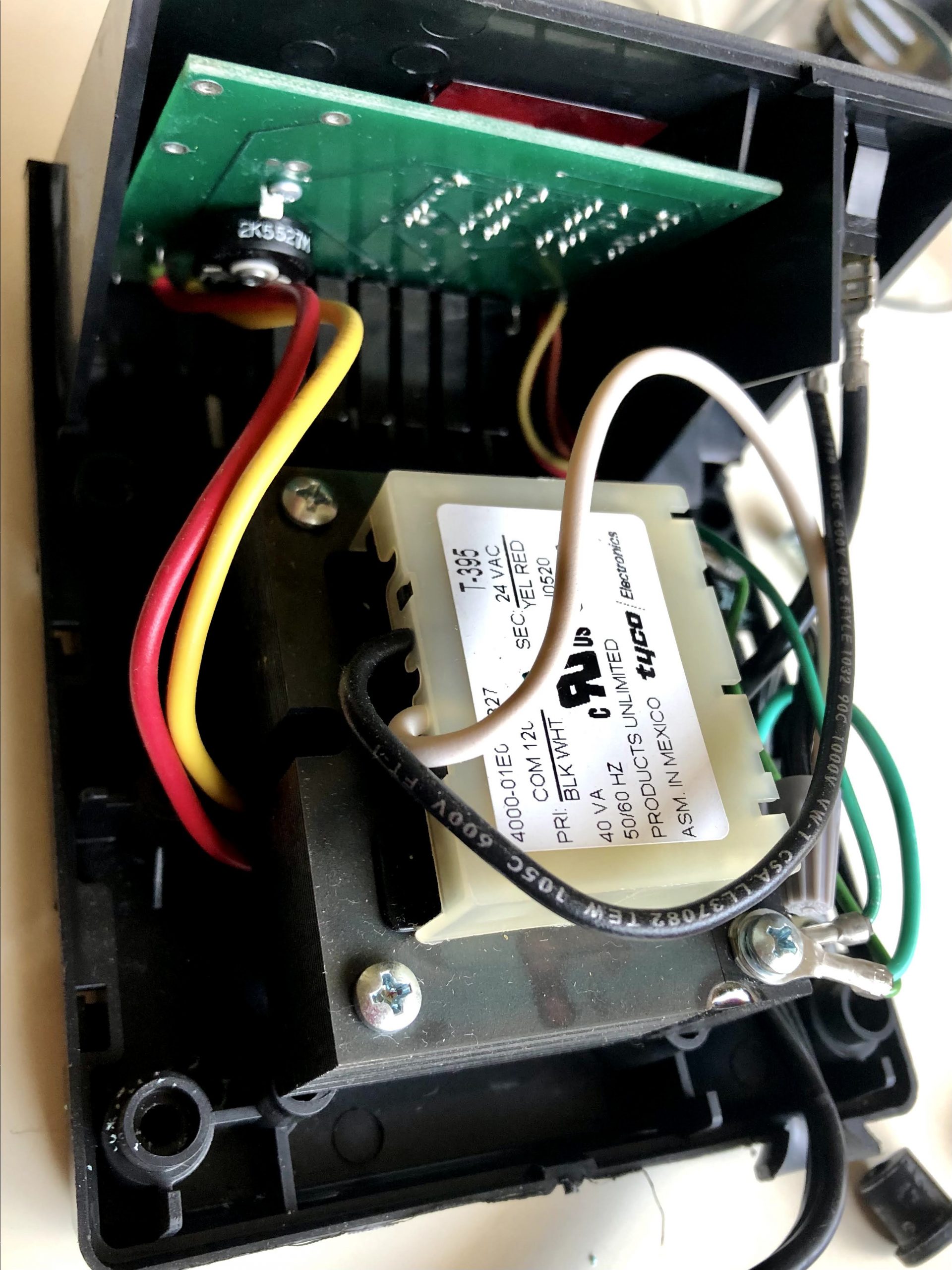
After you remove all four of them, the blue upper body easily separates. Here’s what’s inside:
Step 2: Remove PCB
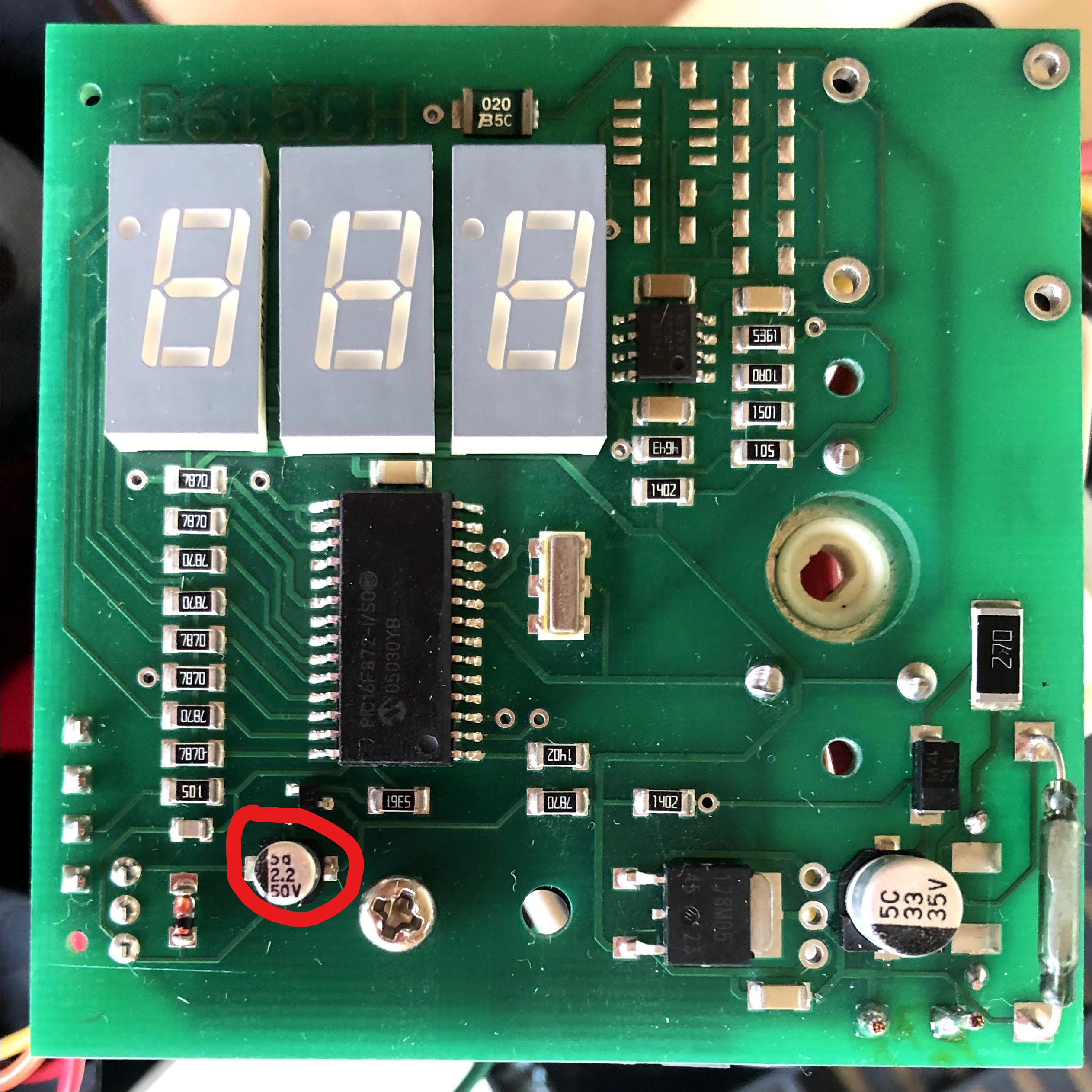
Separate the green PCB from the casing. You don’t have to remove the temperature adjustment knob from the faceplate. Locate the 2.2uF/50V capacitor. It’s circled in red in the photo below:
Step 3: Remove existing 2.2uF capacitor
Carefully desolder the capacitor circled in red above. If you don’t have a capacitance meter, just try swapping in a new part, and see if it fixes the problem.
Step 4: Solder in a replacement capacitor
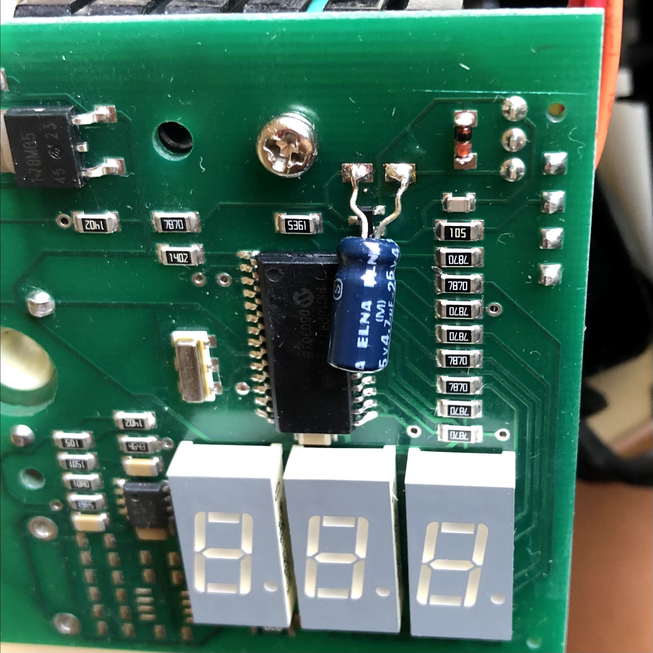
Make sure to pay attention to the polarity of the electrolytic capacitor… the negative terminal faces the line of SMT resistors on the right of the photo above. I didn’t have an exact replacement in my parts bin, so I just used a 4.7uF/25V part… the circuit voltage is 24V, so 25V isn’t much headroom, but it’s easy to replace it again if it fails in the future. Before putting everything back together, I fired it up, and it was heating again!
Downloads: