gCode Visualization

I was working on a project today, which had some serious overhangs. I added support material manually, but needed to make sure that slic3r was traversing a usable path through my supports. Usually, I use Repetier Host‘s excellent built-in gCode visualizer, but it only displays a layer at a time, and I needed to see the actual paths followed in each layer. After searching a bit, I found an excellent online visualizer: gcode.ws:

Image3


It is very full featured, with sliders that let you step through your gCode layer by layer, and also line by line within a layer. Additionally, it prints out a lot of useful statistics within your gCode.

While running it in a web browser is handy, since you don’t need to install any software, sometimes, I need to have access to it when I have no Internet access. Fortunately, the visualizer is open source, and is written in javascript, so you can also run it directly from your hard drive. First, download the zip archive from github:

https://github.com/hudbrog/gCodeViewer/archive/master.zip

Unzip the archive, and simply launch index.html. I had security issues running it in Chrome, and it froze up in Internet Explorer, but Firefox runs it just fine. To run it in Chrome, you must launch it with the command line option “–allow-file-access-from-files” in order to lower the security so that it can access files locally, but it doesn’t work if you already have a running copy of Chrome.

On Windows computers, if Firefox isn’t your default browser, you can just right-click index.html, and select Open with->Firefox.

Image3


Many thanks to hudbrog for making this excellent tool.

Kossel-Linco Delta Printer: Part 1 – Magnetic Effector and Arms + Vertical Carriage

I’m currently designing my first delta 3D printer. It’s based on Johann Rochell’s Kossel Mini, but I’ve modified or redesigned just about every part, except for the bottom vertices. The first design decision I made was to get rid of the expensive linear rails and sloppy Traxx joints. I like the magnetic ball joint concept, because 1) it gets rid of backlash 2) it makes it easier to assemble/reconfigure/repair the printer and 3) it’s just plain cool.

I used OpenSCAD to design the magnetic effector:

eff1

The 3/8″ chrome steel balls are each held to the effector by a 3/8×1/8″ N42 countersunk magnet stacked on top of a 3/8×1/8″ N52 disc magnet. It’s hard to see in the photo, but 3 of the six holes around the inner ring contain 1/8×1/4″ tubular magnets, allowing the toolhead to also be magnetically attached. This will allow me to quickly change toolheads on the effector without having to fiddle with bolts. I am still not sure if the toolhead magnets will be strong enough… only testing will tell. Though quick change could be done by simply swapping out effectors, I don’t like that idea for two reasons: 1) it’s more expensive and 2) different effectors will not be exactly the same, since they are printed, and can also warp, necessitating tweaking every time the effector is swapped.

The first toolhead I designed is a J-Head groove mount for a bowden extruder:

gm1

Note the 3 magnets, which attach the toolhead to the effector. There is also a lip on the bottom of the groove mount, which engages the effector to center it, and make a more firm attachment to the effector. Top view of J-Head toolhead:

gm2

Below is the assembled effector and hot end:

efh1

efh2

The most difficult problem was how to attach the chrome steel balls to my carbon fiber arms. Rather than glue the balls directly to the arms, I decided to attach the balls to screws, and then screw them into the arms. This technique has 3 advantages: 1) it gets rid of the need for accurate, square cuts on the rods, because the length can be fine-tuned by adjusting the screws , 2) the balls are easily replaced, and 3) the screw heads are magnetic, so they self-center and hold themselves to the balls while they’re being attached.

I used chrome steel ball bearings, they are very hard, and therefore wear resistant. However, chrome steel is very difficult to solder, and I don’t have access to a spot welder, so glue was the obvious choice for attachment of the balls to the screws. I tried both JB Weld and super glue:

glueballs

It was very convenient to glue the M4 hex head cap screws by simply first attaching the balls to the magnets. No clamping needed while the glue dried. I tested both for strength, and was not able to pull either of the screws off the balls by hand. Therefore, I decided to go with the super glue, because it’s easier to deal with since it dries in only a few minutes, rather than overnight, and there’s no messy mixing needed. In order to get a good bond, I first scuffed up the bolt head with some sandpaper. Then I cleaned both the bolt head and the steel ball with acetone before applying the super glue. After the glue dried, I tested the strength of each joint. 3 of them were weak enough that I could break the ball off, but after re-gluing them, they were just as strong as the others. Another advantage of using super glue was that it dissolves easily in acetone, so it was very to clean off the residual glue before re-gluing the failed joints.

Though it’s probably not needed, I am going to put tape between the balls and the magnets (note the tape under the leftmost ball):

tape
I bought some UHMW tape to try out, but it’s 7mil thick, and noticeably reduces the attraction between the ball and countersunk magnet. I’m thinking of trying out PTFE mouse tape next (it’s only about 2mil thick), but am afraid that it might be too soft, and wear down quickly. Surprisingly, regular old Scotch tape seems to work OK (it’s about 2mil thick),  so that’s another alternative to try.

For the arms, I’m using graphite strong wall rods from tridprinting.  The inner diameter of these tubes is conveniently, slightly smaller than my M4 cap screws. I used cutting wheel on a dremel with a flex shaft attachment to cut them down to size:

dremel

The flex shaft was necessary, because without it, I couldn’t cut perpendicularly to the tubing, since the cutting wheel is a smaller diameter than the dremel body. There are plenty of tutorials on how to cut carbon fiber tubes. The most important points are: 1) to put tape around the area of the cut to reduce splitting, and 2) to wear a mask to avoid inhaling the dust. To help prevent splitting when tapping out the holes for the M4 bolts, I printed out one of Ultibot’s excellent Delta Printer Arm Tap Jigs. The upper section was too long, so my tap couldn’t reach the rod, so I had to saw off a portion of it:

tap

To get the rods all the same length, just put a few bolts onto a piece of 1515 extrusion to build an assembly jig:
jig1

jig2

I didn’t end up using the nuts you see in the photos to lock the bolts, because in order to get them tight enough, they were putting too much pressure on the rods, causing them to split. Instead, I just dripped a drop of super glue into the junction of the rod & bolt. Loctite would probably be a better idea, but I didn’t have any handy. Below is my vertical carriage design:

vc1

The vertical bolt running up the right side is the tensioner. I was delighted that the carriage appears to be rock solid. I was expecting to have to refine it a few times, but my first try seems to be pretty good. We’ll see once I get the printer up and running if I’m right. I bought the roller wheels from deltaprintr.

vc2

I am not entirely happy with the deltaprintr wheels for two reasons: 1) some of them have minor flat spots, so the movement isn’t perfectly smooth, and 2) there’s no internal shim between the bearings, to keep the lateral load off the ball bearings when you tighten them down (unlike makerslide wheels), so the bearings bind a bit when you try to tighten them down. Also, the bearings will wear out faster.

Note that the designs I described above are preliminary, because I am not yet finished building the printer. There are bound to be changes once I start testing it.

Update 2015-07-24: Unfortunately, I got bogged down by my fishing line drive, and was never able to get the machine calibrated. I got too busy to work on it, and it’s been gathering dust for the past year, unfortunately. The design files are all on YouMagine: https://www.youmagine.com/designs/kossel-linco

RepRap: Fish Pump Hot End Tip Cooling

I have always had trouble printing small parts and overhangs, because I was too lazy to add cooling to my hot end tip. I sometimes used to just blow a USB fan at the printer, but this has two bad effects: 1) the cooling isn’t localized enough, so it doesn’t work very well, and 2) the unfocused air flow cools down the heat bed, which can cause the print to detach. I looked at a bunch of fan shrouds that other people have been using, and didn’t like the way that most of them still leak a lot of air onto the hot bed. The thought occurred to me that the air coming out of the hose of an aquarium air pump is quite focused, so I decided to hack something together to test it out.

This is a fish pump that I happened to have laying around:

fishpump

I used silicone airline tubing, because it’s more flexible than the regular clear tubing, and doesn’t harden with age, and is heat resistant. Here is my messy hack to test out the concept:

nozzlecool

The silicone tubing is held in place with a couple of bent up paper clips. I love my J-Head Mk III-B – it works flawlessly, even without fan cooling the aluminum heat sink, but one annoying thing is that the nozzle is very short, so there’s very little clearance between the nozzle tip and the heat block. This made placement of the cooling hose sub-optimal. It’s very hard to position the hose to cool the flow of plastic without hitting the print. Nevertheless, much to my delight, it works pretty well! Below is a comparison of printing with and without nozzle cooling. The part is a holder for a steel ball from Steve Graber’s Cerberus Pup. The print on the left was done without nozzle cooling, and the print on the right with cooling:

cooling1

The view above is from the bottom of the part, so the flat part inside the hole was an overhang. Note what a mess it made of the uncooled part. Below is a top view of the part:
cooling2

The cooled part was a perfect, tight fit for a 3/8″ steel ball bearing. I was amazed how accurately the part came out.

cooling3
Being the lazy person I am, I’m going to keep the jerry-rigged setup until it falls apart. So far, it’s been holding up quite well, allowing me to print out all of the parts for the Kossel-Linco delta printer that I’m designing. There are 3 main downsides to using the fish pump rather than a fan: 1) the pump is rather noisy 2) It uses AC power, so a relay is needed in order to control it via software, and 3) it’s difficult to control the air flow by software. What I’ve been doing is to start the print with the pump off, and then turn it on after the first few layers are done printing.

Slic3r Support Material Frustration

It’s been a few years since I’ve played with Slic3r, so I was eager to play with the current stable version, v1.0.1. One problem I had when playing with earlier versions of Slic3r was that the support material generation was not yet usable. A part I was designing had a big circular overhang in the middle, so it was the perfect opportunity to try out support meterial in v1.0.1 stable. Unfortunately, while the support material worked great for printing, it was almost impossible to remove! The gcode depicted below was generated using the rectlinear pattern:

slic3r101stable

The support material in the above picture is the large circular plug. Notice how it doesn’t leave a gap between the plug and the hole, so it’s completely stuck to the part! It took me almost an hour to carefully dig the support material out with and x-acto knife. Unfortunately, there’s no parameter in v1.0.1 to let you tune the spacing between the support material and vertical walls. Next, after reading that the Slic3r team had rewritten the support material code, I downloaded the latest experimental version, 1.1.4, and tried it. Much better:

slic3r114

Note the sizeable gap between the support plug and the perimeter of the hole. This time, the supports only took a few minutes to remove. The moral of the story? Use a newer version of Slic3r instead of v1.0.1 stable if you want to generate easy to remove support material. An added bonus of v1.1.4 is a new support pattern, called pillars. It looks like this:

pillars

RepRap: Printrboard Surgery

After a hiatus of a couple of years, I’m finally starting to get back into 3D printing. One of my Printrboards got messed up when some wires on my hot end shorted. The hot end temperature was no longer reading correctly. Since my other Printrboards all work correctly, I knew that the problem was not a bad thermistor or wiring. Instead of throwing out the Printrboard, I decided to try to fix it. The first step was to have a look @ the Printrboard schematic. Here’s what the temperature sensing circuit looks like:

tempckt


I got out my ohmmeter, and R9 was OK, but E-THERM to GND was reading as a dead short, so I assumed that C10 was bad. This was a good opportunity to play with my AOYUE INT 2702 hot air rework station, which I’d never used. I removed C10, and much to my chagrin, the reading from the hot end ADC pin was stuck at 1024. Furthermore, shorting E-THERM to ground was causing my Printrboard to reboot! This led me to conclude that something was fried inside the AT90USB1286 on the ADC pin connected to E-THERM (PF1_ADC1). Conveniently, 2 other ADC pins, ADC2 and ADC3, are broken out into an expansion header on the Printrboard. I first soldered C10 back into place. The trace connecting ADC1 to E-THERM was inaccessible, so I couldn’t cut it. Instead, I disconnected it by lifting the pin on the MCU off the PCB. Next, I connected a piece of 40AWG wire wrap wire between the A2 header pin and the E-THERM trace.

pbfix

Success, the ADC2 pin is working perfectly! The only caveat is that I have to remember to run modified firmware when using this board, reassigning the hot end thermistor pin from ADC1 to ADC2. In Marlin firmware, it’s as simple as finding the Printrboard section of pins.h, and reassigning TEMP_0_PIN from 1 to 2.

Arduino 1.0.5-r2 for AT90USB1286 and Printrboard

It’s been a few years since I hacked together the copy of Arduino-0022 that’s been floating around the web, which lets you compile and automatically upload Arduino code to an AT90USB1286. This made it a lot easier to develop Arduino code for the AT90USB1286, and in particular to easily modify the Marlin firmware for the Printrboard.

Yesterday, I figured it was high time to add AT90USB1286 support to Arduino 1.0.5-r2. The basic procedure for the modification was to first install Teensyduino, which adds the AT90USB1286 compilation support to Arduino, but only uploads to a Teensy++ 2.0, running PJRC’s proprietary halfkay bootloader. I modified the Teensyduino configuration to also support uploads to targets running the LUFA CDC Bootloader, or via USBtinyISP or USBasp ICSP programmers.

Note that I copy that I modified only runs on Microsoft Windows.
You can download it from github: https://github.com/lincomatic/arduino-1.0.5-r2-at90usb1286
It’s easiest to download it as a zip file: https://github.com/lincomatic/arduino-1.0.5-r2-at90usb1286/archive/master.zip

Once you unzip the archive and launch arduino.exe, you will notice some new entries in the Tools->Board menu:

[USBasp]AT90USB1286
[usbtinyisp]AT90USB1286
[BootloaderCDC]AT90USB1286
[USBasp]Printrboard
[usbtinyisp]Printrboard
[BootloaderCDC]Printrboard

The only difference between the Printrboard and AT90USB1286 entries is that the extraneous USB Type, CPU Speed, and Keyboard Layout submenus are grayed out from the Tools menu.

To load Marlin firmware onto a Printrboard, you will most likely want to use [BootloaderCDC]Printrboard.

Note that unlike my Arduino-0022 hack, the pinMode()/digitalRead()/digitalWrite() functions in version currently only support the pins that are exposed on the Teensy++ 2.0. This is because I haven’t yet had the time to figure out how to add in the remaining AT90USB1286. However, this limitation doesn’t affect Marlin firmware on the Printrboard, because Marlin uses its own fastio functions, rather than using Arduino digital pin numbers and pinMode()/digitalRead()/digitalWrite(). See pinmap.txt for the currently supported Arduino digital pin numbers.

Thanks again to PJRC for Teensyduino. Teensys are a great alternative to Arduino boards.

Tweaking the Action on a Roland FD-8 Hi-hat Pedal

Ever since I bought my Roland TD-3SW v-drum kit, I’ve found the included FD-8 hi-hat pedal to be a major annoyance. The problem is that I would practically have to stand on the pedal in order to get the hi-hat closed sound. Adjusting it according to the instructions in the manual didn’t help. I basically lived with it this way until my son recently wanted to start using my drum kit, and couldn’t apply enough force to the FD-8. It was time to fix the problem.

I googled around and found a few fixes, notably this discussion on vdrums.com: FD-8 Hi-hat Controller Pedal – Notes on Improving Volume and Feel. However, I felt that the fix described in the thread seemed too hacky for my tastes. Finally, I found this video on YouTube by a brilliant German guy: How to fix a Roland FD-8 hihat pedal. I decided to try his method, and it worked great! My pedal now has action a lot more like a real hi-hat pedal; you don’t have to mash it down hard to get the “closed” sound. I’ve modified the procedure a little, and have documented it below:

Step 1: Remove screws

In the YouTube video, Marcel practically tears down the entire FD-8. Actually, you don’t really have to disassemble everything. All you need to do is get access to the problem parts. Remove only the screws pictured in the photo below from the bottom of the pedal:

screws

This will allow you to separate the front plastic cover from the metal bottom. The bottom metal plate has a resistor attached to a small PCB via a ribbon cable, which is attached to the 1/4″ TRS jack. This is what the resistor looks like:

resistor

There is a rubber foot (show in a photo below), which presses along the resistor in order to tell your drum’s brain box the position of the pedal. The problem is that the rubber foot doesn’t press hard enough against the section that indicates hi-hat closed (low resistance), near where the ribbon cable connects.

When you open the case, the ribbon cable will be attached to the grey clip pictured below:

cableclip

To release the ribbon cable, simply pull upwards on the grey part of the clip until it stops. Then the ribbon will easily slide out of the slot. The rubber foot is attached to the underside of the plastic cover:

rubberfoot

The problem is that the rubber foot is extremely stiff, and doesn’t bend as easily as it should. To remove it, gently rock it back and forth while pulling upwards. In the video, Marcel sprays silicone lube on it to loosen it up, but mine wasn’t that tight.

The method shown in the video is to soften up the rubber foot by thoroughly coating it with petroleum jelly and letting it sit in a warm place overnight. Since petroleum jelly eats rubber, I decided to apply it only on the part that affects the flex action, and not on the contact surface:

foot1

In particular, notice how I avoided applying petroleum jelly to the narrow protruding ridge. This keeps it from softening the ridge, which we want to remain hard, to maximize the pressure and lessen wear.
foot2

I left the rubber foot on top of my cable TV set top box (a consistent heat source) overnight. The next morning, the rubber was considerably softer, and I could tell that it was taking a lot less force to flex it. Again, here’s where I deviate from Marcel’s video. He initially applies the petroleum jelly a lot thicker than I did, and says to wipe it off after the rubber softens, leaving a layer that’s approximately as thick as what I applied in my photos above. Instead, I wiped the petroleum jelly residue completely off with a paper towel. I figured that some of it would still be soaked into the rubber, and that would be enough. Better than having it eat through the rubber until it turns to mush.

Reassembly of the pedal is just the reverse of the dis-assembly steps. When re-inserting the ribbon cable into the gray connector, make sure the gray connector is pulled up while inserting the ribbon cable, and then press it down to lock the cable in place. Also, be sure that the metal tongue pictured below has a layer of silicone grease on it:

actuator

Mine still had enough lube on it from the factory, so I didn’t apply any extra. The rubber foot slides against this metal tongue when you press the pedal, so if it isn’t lubed properly, the pedal may need extra pressure. DO NOT use petroleum jelly here, because it will slowly melt the foot, and probably turn it into mush over time. Silicone lube, on the other hand, does not react with rubber. You can get small quantities of silicone grease in most auto parts stores.. it’s used on the rubber bits of brake parts. Also, you can buy it pool supply stores, or at a hardware store. This cheap stuff at Home Depot should work OK: Silicone Faucet Grease.

My pedals has great action now! I’m not sure if it will harden up in a few months, but the hack is easy and I’d rather play the hack on the conservative side. An alternative hack would be to drill holes along the side of the rubber foot, thus lessening its tension. I was originally going to do this, and it turns out someone on vdrums.com successfully did it (see the the 2nd to last post on this page), but in the end, I decided to first try the petroleum jelly method, since it was less invasive. Thanks again to Marcel (vdrumtips).

How to Update the Firmware on a USBasp V2.0

REVISED 2018-07-16

If you buy a cheap USBasp V2.0 ICSP programmer on eBay, chances are, avrdude will give you the following warning message:

avrdude: warning: cannot set sck period. please check for usbasp firmware update.

While it’s just a benign warning message which can be ignored with no ill effects, it’s still a constant irritant. Furthermore, it also prevents my speed up technique from working, because it relies on changing the sck period. To get rid of the warning, you must update the firmware to the latest version: usbasp.2011-05-28.tar.gz

If you have another ICSP programmer already, such as a USBtinyISP, programming in the new firmware is quite simple. If you have more than one USBasp, you can even use them to program each other. Here are the steps:

0. Verify that you have a USBasp V2.0, and that it has a 12MHz crystal and an ATMEGA8 or ATMEGA8A MCU onboard. DO NOT CONNECT IT TO THE USB PORT OF YOUR COMPUTER.

1. Short the JP2 (self-programming) jumper.

2. Connect the USBasp V2.0 to the USBtinyISP (or other ISP) using a 10-pin ribbon cable

usbasp

3. Flash in the new firmware: avrdude -c usbtiny -p atmega8 -U flash:w:usbasp.atmega8.2011-05-28.hex

4. Reprogram the USBasp’s fuses: avrdude -c usbtiny -p atmega8 -u -U hfuse:w:0xc9:m -U lfuse:w:0xef:m

If you’re not using a USBtinyISP, substitute the proper parameter after -c (e.g. -c usbasp).

Note that the usbasp.2011-05-28.tar.gz archive doesn’t contain a compiled .hex file, so you have to re-compile it using WinAVR. Instead, you can just use my hex file, which I compiled directly from the sources: usbasp.atmega8.2011-05-28.zip

If you don’t have another ICSP programmer, you can use an Arduino, following these instructions: Updating firmware on USBASP bought from eBay. However, you may also have to also set the fuses according to Step 3 above. My PC wouldn’t recognize the reprogrammed USBasp until I set the fuses.

Interfacing a TFT_320QVT LCD/Touchscreen/SD to a Teensy 3.0

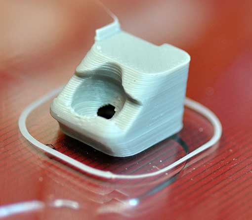
I’m working on a project which needs a touchscreen LCD. After searching eBay for a while, I noticed that many vendors were selling basically the same 3.2″ 320×240 TFT with resistive touchscreen and SD card reader. Though there were slight variations in the silkscreens, they all had the same model number – TFT_320QVT. I bought mine from digitalzone88 for $12.29. TK0466-1-digitalzone88 TK0466-4-digitalzone88 
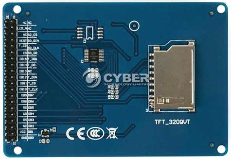
The board uses a SSD1289 LCD driver IC, and runs on 3.3V. The 3.3V voltage is incompatible with the typical Arduino, which runs at 5V (some vendors have created shields to interface it to an Arduino Mega). However, I purchased the TFT_320QVT with the intention of interfacing it to a Teensy 3.0, which runs at 3.3V. I noticed that there were not enough through-hole I/O pins on Teensy 3.0 to simultaneously interface to the LCD, touchscreen, and SD card. This necessitated the usage of the Teensy 3.0’s additional I/O pins, accessible only via solder pads on its underside: teensy3b 
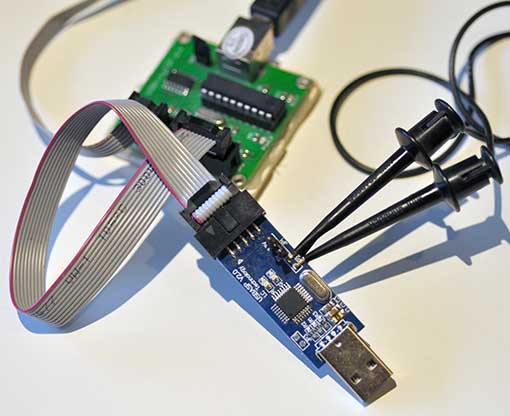
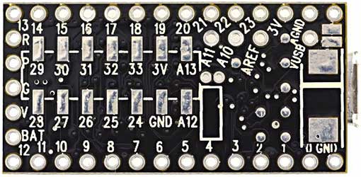
To facilitate access to the 14 solder pads, I attached some header pins to piece of stripboard, and soldered 40AWG wire-wrap wire to between the pads and headers: extender
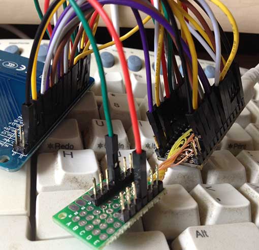
The Teensy 3.0 runs on PJRC’s specially modified version of Arduino – Teensyduino. The task was to find compatible Arduino libraries. First order of business was the LCD. I searched the web, and found that dawnmist had spent a considerable effort in modifying Henning Karlson’s UTFT to work with the Teensy 3.0. Unbeknownst to me at the time, dawnmist’s modified UTFT is actually bundled with Teensyduino!

Next, was to get the touch screen working. It turns out that the current version of Henning Karlson’s UTouch is compatible with the Teensy 3.0.

For the SD slot, I tried the version of the Arduino SD library that’s bundled with Teensyduino. Unfortunately, though the SD library works with the TFT_320QVT’s SD reader, it stops working if you instantiate a UTFT object in the sketch. I tried sdfatlib, and found that not only does it work w/ the Teensy 3.0, but it coexists fine with UTFT. The only catch I found is that it works only with SPI_HALF_SPEED. When I set it to SPI_FULL_SPEED, it stops working.

Here is the Teensy 3.0 running UTFT‘s demo sketch on the TFT_320QVT: utft

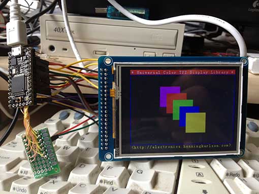
Below is the step-by-step procedure to getting the TFT_320QVT up and running with Teensy 3.0:

Step 1: Install the libraries

1. UTFT: Run the Teensyduino installer, and when the Libraries to Install dialog is displayed, check the box next to UTFT in the Choose Additional Libraries to Install combobox. (Note: Henning Karlson’s latest UTFT also works with Teensy 3.0, but my discussion below will show how to interface to the UTFT that’s bundled with Teensyduino 1.18).

2. UTouch: Download UTouch.rar. Use WinRar or 7-zip to extract the enclosed UTouch folder. From the Arduino IDE pull-down menu, use Sketch->Import Library->Add Library… to install the extracted UTouch folder. Alternatively, you can just copy Utouch/ to your arduinosketchbook/libraries directory.

3. sdfatlib: Download the latest version of sdfatlib. From the Arduino IDE pull-down menu, use Sketch->Import Library->Add Library… to install the downloaded sdfatlibyyyymmdd.zip file. You can alternatively just extract the SdFat/ folder into your arduinosketchbook/libraries directory.

Step 2: Wire it up

1. LCD: dawnmist‘s modified UTFT library that’s bundled with Teensyduino has a configuration file: arduinofolder\libraries\UTFT\hardware\arm\HW_Teensy3.h. Inside HW_Teensy3.h, there are 3 options for the LCD pin assignments: USE_B_D_PORTS, USE_C_D_PORTS, and USE_USER_PORTS. By default, the file has

#define PORTS USE_B_D_PORTS

enabled. USE_B_D_PORTS gives the best performance when your sketch needs to use SPI (which is needed for the SD card slot). USE_C_D_PORTS gives the fastest performance, but is incompatible with SPI. USE_USER_PORTS allows you to configure arbitrary pins (by changing the DB_0-DB_16 #defines), but results in the slowest performance. I elected to use the default USE_B_D_PORTS setting.

2. SD card reader: The SD card reader works via SPI, so it needs to use SD_DIN->DIN (MOSI – 11), SD_DO->DOUT (MISO – 12), SD_CLK->SCK (13), and one of the chip select pins, CS0-CS4 (10,9,20,21, or 15). I chose to use SD_CS->CS4 (15).

3. Touchscreen: The touchscreen uses 5 pins, T_DIN/T_DO,T_CS/T_CLK/T_IRQ, which can be assigned to any arbitrary free GPIO pins.

Below is a chart of my pin assignments:

Teensy_pin = TFT_320QVT_pin
0 = LCD_DB4
1 = LCD_DB5
2 = LCD_DB8
3 = LCD_LED_A (backlight)
5 = LCD_DB15
6 = LCD_DB12
7 = LCD_DB10
8 = LCD_DB11
9 = LCD_REST (RESET)
11 = SD_DIN (MOSI)
12 = SD_DO (MISO)
13 = SD_CLK (SCK)
14 = LCD_DB9
15 = SD_CS
16 = LCD_DB0
17 = LCD_DB1
18 = LCD_DB3
19 = LCD_DB2
20 = LCD_DB13
21 = LCD_DB14
22 = LCD_WR
23 = LCD_RS
24 = T_CLK
25 = LCD_DB7
26 = T_CS
27 = T_DIN
28 = T_DO
29 = T_IRQ
32 = LCD_DB6

LCD_RD needs to be pulled up to 3.3v

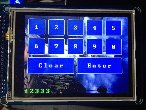
I have created a sketch, UTFT_UTouch_SdFat_teensy3, that simultaneously demonstrates the LCD, touchscreen, and SD card by modifying the UTouch demo sketch. Below are the lines which are critical to configuring it to work with the above pin connections:
[code language=”c”]
#include <UTFT.h>
#include <UTouch.h>
#include <SdFat.h>

// bitmap file to load as background.
// must be 320×240 and in format output by ImageConverter565
char bkgRaw[] = "ade.raw";

uint8_t sdCS = 15; // SD_CS – chip select
SdFat sd;
SdFile inFile;

uint8_t lcdRS = 23;
uint8_t lcdWR = 22;
uint8_t lcdCS = 4;
uint8_t lcdReset = 9;
uint8_t lcdBacklight = 3; // must be a PWM pin for variable brightness
uint8_t lcdBacklightBrightness = 255; // 0-255
UTFT myGLCD(SSD1289, lcdRS, lcdWR, lcdCS, lcdReset);

// Initialize touchscreen
uint8_t t_Clk = 24;
uint8_t t_CS = 26;
uint8_t t_DIn = 27;
uint8_t t_DOut = 28;
uint8_t t_IRQ = 29;
UTouch myTouch(t_Clk, t_CS, t_DIn, t_DOut, t_IRQ);
[/code]

The file displays a bitmap, ade.raw, as the background. Before running the sketch, copy ade.raw to a FAT-formatted SD card, and insert it into the TFT_320QVT’s SD card slot.

You can also substitute your own bitmap file. To create a .raw file, first create a 240×320 pixel jpg, png, or GIF file. Run it through either imageconverter565.exe (bundled with UTFT) or the online ImageConverter 565 make sure to select Convert to .raw file and Target Platform Arduino (AVR).

Here’s what UTFT_UTouch_SdFat_teensy3 looks like when it’s running:
btntest

Many thanks to dawnmist, and the others who figured out how to get UTFT working with the Teensy 3.0.

Downloads:
UTFT_UTouch_SdFat_teensy3
UTFT_demo_tft_320qvt_teensy3

Links:
I obtained much of the information I needed from these pages:
dawnmist – screen working … finally
Teensy 3.0 – driving an SSD1289 with utft

Arduino IDE suddenly freezing up? Here’s how to fix it.

Every once in a while, my Arduino IDE suddenly takes forever to launch, sticking at the splash screen for a long time. Even after it launches, it’s still basically unusable, because the pull-down menus also freeze up, and take an eternity to respond. It happens to me every time I download a new Arduino IDE, which is so infrequent that repeatedly forget why it happens, and how to fix it. After ripping my hair out for a while, I start googling until I find the fix.

If you’re experiencing this problem running Arduino on Microsoft Windows, chances are, you have a virtual serial port from a Bluetooth SPP device installed in your system. The problem is that the Arduino IDE is trying to enumerate your system’s serial ports in order to locate the attached Arduino devices, and the code takes a long time to timeout. Luckily, user eried in the Arduino forums figured out what was happening, and posted a fix in the thread: Road to solve the delay in Arduino IDE. He has graciously come up with a workaround, and shared it with us.

The fix is easy. Simply download his rar file, extract his new rxtxSerial.dll, and replace the version that’s currently in the same directory where your arduino.exe resides. I’ve also attached a zip archive of the file below, for those people who don’t want to install WinRAR in order to get the new rxtxSerial.dll. Thanks, eried!

Downloads: rxtxSerial-2.2_fixed_2009-03-17.zip