EKitsZone UNO Rev.3 First Look

I recently decided to buy an Arduino UNO R3, to test compatibility with my sketches, which I have been testing w/ a Deumilanove.  The UNO R3 contains an ATmega16U2  instead of an FTDI chip to do the serial to USB conversion, as well as 3 extra pins on the digital side of the board: SCL/SDA/AREF.  One thing I don’t like about the Arduino UNO is that while it uses a 16MHz crystal for the 16U2, the main 328P MCU runs on a resonator, which is not as accurate.  I found the EKitsZone UNO Rev.3 on eBay for $14.99, and decided to give it a try.

unor3The notable differences in the EKitsZone Rev.3 versus the Arduino UNO R3 are:

  1. the ATmega328P uses a 16MHz crystal oscillator instead of a resonator, so its timing is just as accurate as a Deumilanove
  2. the reset button is mounted at a right angle, so it’s easily accessible even when a shield is attached on top
  3. it uses a mini-USB connector instead of a full-sized one
  4. the JP2 pins aren’t filled with solder, so it’s easier to solder in headers, should you want to connect something the PB4..PB7 pins on the 16U2
  5. the programming header for the 16U2 isn’t installed, but it’s easy to solder one in

I see 1-4 as advantages.  Plus, the board is a cool looking red color.

Build Ganzfeld-style Photic Goggles (AVS Lightframes)

Building upon my passive Ganzfeld goggles, I decided to build a set of Ganzfeld-style lightframes for photic brain stimulation.  I was inspired by the goggles which come with the very expensive Laxman mind machine:

laxman

Typical lightframes which come with audio-visual stimulation (AVS) mind machines use point source LEDs, such as this pair which came with my MindPlace Sirius mind machine:

siriusgoggles

I covered the basics of how to construct such goggles in a previous article: Build an Audio Player Based Mind Machine Part 1: Photic Goggles

Even the RGB “ganzframes” which come with the MindPlace Procyon mind machine are rather feeble, consisting of point source SMT LEDs, covered by a simple roughened square of translucent plastic… the effect is only mildly diffuse, and still looks like a cluster of point sources.  Inspired by Michael Rule’s hallucinogenic goggles project, I modified his goggles design to my tastes, and built a monochrome replacement for my Sirius lightframes.

Parts for this project:

parts

BOM

  • wiring harness from cheap headphones (a pair of earbuds from your local 99 cent store are a good donor)
  • 2 LEDs – I chose white LEDs
  • a ping-pong ball – I already sliced it in half in the photo.  Using the seam as a guide, cut it in half with a very sharp x-acto knife
  • passive ganzfeld goggles prepared as described in my previous article:  Relax Your Mind: Build Your Own Ganzfeld Goggles

If you your LEDs are of the clear point-source variety, it’s a good idea to scuff them up a bit with to make them more diffuse. You don’t have to do the whole LED.  Rubbing the tip with sandpaper will suffice:

ledscuff

Trim the LED leads, and solder them to the headphone wires:

soldering

The polarity of the wiring depends on the requirements of your particular mind machine.  My Sirius mind machine uses common-anode wiring (also known as CP or common-power), so the anodes connect to ground, and the cathodes go to the right and left channel signal leads.  If your mind machine requires common-cathode wiring (aka CG/common-ground), then you should connect the cathodes to ground, and the anodes to the left and right signals.

After soldering the LEDs, drill a small hole in the side of each ping-pong ball half (I actually just twirled the tip of my x-acto knife, rather than using a drill bit), and then tack them to the balls with hot melt glue.  The blob of glue that holds the tip of the LED to the ball actually helps to diffuse the light a bit more.  Notice that the LED’s are pointed toward the ball instead of away from it, so that you instead of shining the LED beam into your eyes, it bounces off the ball.

ledplacement

Next, carefully glue the ping-pong ball halves to the front of the goggles.  Tack one side of the ball, wait for it to harden, and work your way around it a section at a time, while bending it to conform to the shape of the goggles.  Be careful of overheating when applying hot glue to the ping-pong balls.  My glue gun was a bit hot, and the heat warped them a bit. Notice the flattened parts of the balls below:

melted

Here are the completed goggles:

completed

They work fabulously … much better than conventional point-source lightframes, and an added bonus is that they can be used with eyes open.

monogoggles

Plus, they look really cool & trippy: goggleshead

Here is a preview of my hallucination machine. It’s a standalone Arduino-based mind machine, which is my remix Michael Rule’s Hallucinogenic goggles.  The goggles are of identical design, but use RGB LEDs rather than a single color.  I will document the build in a future article.

hallucinationmachine

Related Post: Relax Your Mind: Build Your Own Ganzfeld Goggles

Build a Bluetooth Low Energy (BLE) Controlled RGB LED

I have been wanting to play with my RedBearLab BLE Shield for some time, but have been too busy. This weekend, I finally was able to allocate some time to experiment with it. I decided to do something relatively easy as my first project, so as to familiarize myself with the Bluetooth API’s on both the Arduino and the host side. Wirelessly controlling an RGB LED seemed like something fun to do.  RedBearLab has some example programs for Mac OSX and iOS in their BLE SDK.  I decided to start with OSX, since the compiler and SDK are a free download from Apple.

One nice thing about BLE is that you can write iOS apps that talk to it without going through Apple’s expensive MFA program.  Apple is being asinine, as usual, and decided not to support the RFCOMM profile, which allows older versions of Bluetooth to emulate serial ports, and talk to arbitrary devices.  However, they still force you to pay them $99 per year (yes, per year, not a one-time fee) for the *privilege* of being able to run your own iOS apps on an actual device.  Annoying and evil…

While recent Apple computers have Bluetooth 4.0 support built-in, I have an older Mac Book Pro from 2008.  I bought a cheap CSR BT 4.0 dongle on eBay for <$10.

My Mac is running OSX Mountain Lion, but I was not able to get it working at first, even though I followed the hack described at: https://discussions.apple.com/thread/2265096?start=0&tstart=0. (Note: I deleted the bcdDevice key, rather than updating it as described in the article).  Then I noticed that Apple wanted to install an OSX update.  Once I updated to OSX 10.7.5, the dongle started working properly.  What’s strange is, with the update, I found that there is actually a kext which is configured to directly support my dongle (USB VID = 0x0a12, PID = 0x0001) straight out of the box, but for some strange reason, OSX was detecting it as a Broadcom device, rather than Cambridge Silicon Radio.  While the dongle is working now with the hack, it is a bit flaky on my Mac, and sometimes can’t talk to the BLE Shield, unless I unplug/plug it in or retry several times.  On the other hand, it works flawlessly on my Windows 8 machine.  If anyone knows of a cheap and reliable BT 4.0 dongle for OSX, please leave a comment below.  FYI, when you plug in the BT 4.0 dongle, OSX automatically disables the built-in Bluetooth controller.

Schematic:

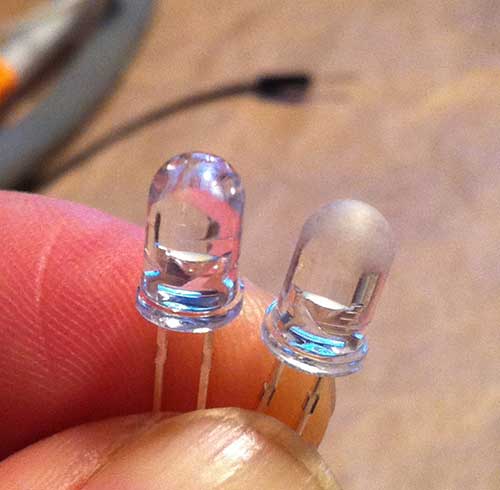
I used a common-cathode RGB LED.  Here is the schematic:


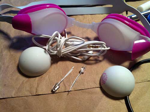
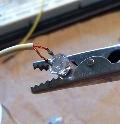
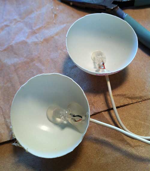
The brightness of each color channel is controlled via PWM, using a value from 0-255.  The BLE Shield uses pins D8 and D9 for communication.  My Arduino Duemilanove has 6 PWM pins: D11, D10, D9, D6, D5, and D3.  Therefore, I decided to use D6=red, D5=green, and D3=blue. I wired it up on a mini protoboard.  To diffuse the light, I drilled a small hole into a Ping-Pong ball, and attached it to the LED.  Here is my test rig:


I have uploaded all of the code for this project to github: https://github.com/lincomatic/BleRgbLed

Arduino Sketch:

The Arduino code for this project is in BleRgbLed.ino.  Before you can compile the sketch, you must install the BLE Arduino library.  Simply unzip libBLEShield_v1.0.zip into <arduinosketchbook>/libraries.  You will have two subfolders, BLE/ and BluetoothLowEnergy/.

To maintain communication integrity between the host and the Arduino, I decided to implement a simple 5-byte packet format:

<sync byte><red><green><blue><checksum>

where

 <sync byte> = 0xA5

and

<checksum> = <red> XOR <green> XOR <blue>

This way, if the signal drops out or some packets get corrupted, the Arduino can reject bad data, and easily regain sync.

OSX Cocoa App:

The Mac OSX app is very straightforward, using 3 sliders, one for each color, to control the LED:

As a template, I used RedBearLab’s SimpleControl_Mac example, which is included in their BLE SDK.  To compile the app, your Mac must be running OSX 10.7.2+, and you must use XCode 4.2+. To compile an OSX or iOS app that talks to the BLE shield, you must add two frameworks to your project:  1) BLE_Framework from RedBearLab’s SDK and 2) IOBluetooth.framework from Apple’s SDK.

It would be very straightforward to port the app to iOS, using the SimpleControl_IOS sample as a template, but I haven’t done it yet, because my Apple Developer license expired, and I don’t want to spend another $99 for a new one.  It is supposedly possible to run it on your Mac via the iOS Simulator without a developer license, but I wasn’t able to get the simulator to connect to the BLE shield through my BT4.0 dongle.  iPhone 4S/5 and late model iPads have BLE built-in.  I believe you need to be running iOS 5.1+ to use BLE API’s.

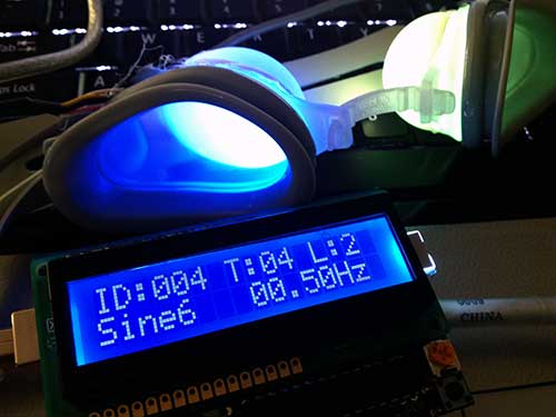
Here is what it looks like in a darkened room.  It’s bright enough to make a nice night light. It looks a bit like an Ambient Orb, and with a bit of extra coding, could actually behave like one. With some transistors to drive more current, you could drive RGB LED strips, and make multicolored under-counter kitchen lighting.

I think it would be cool to use the LED as a notifier for SMS messages, voice mail, etc for an iPhone, but I am not yet sure whether or not the proper API’s are available.

I am more comfortable programming Microsoft Windows apps… if anyone has any good examples for getting started with BLE communication API’s under Windows, please leave a comment below.

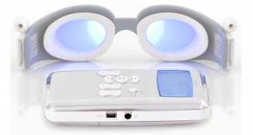
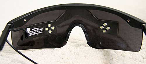
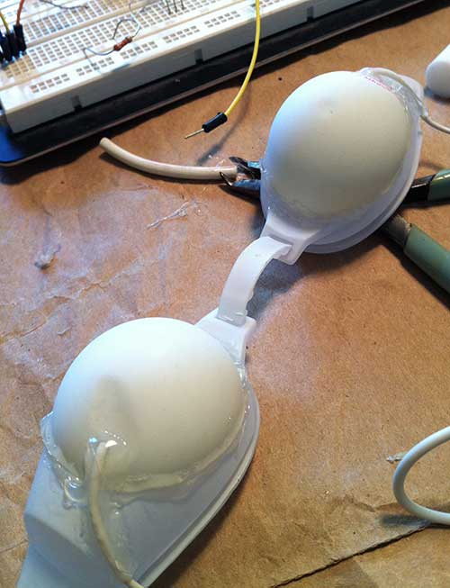
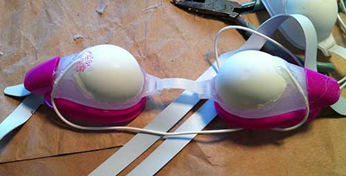
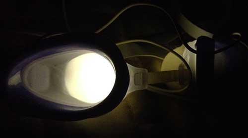
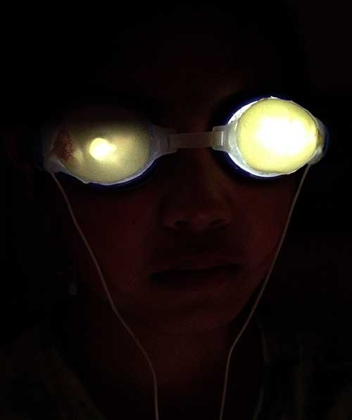
One of my goals is to build wirelessly controlled RGB LED goggles for photic brain stimulation – once I get this working, I will post a blog entry.

Code Download: https://github.com/lincomatic/BleRgbLed

Previous Post: RedBearLab BLE Shield – First Look
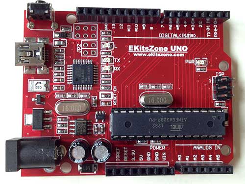
LiquidTWI2 v1.1.0 Released

For the Adafruit RGB LCD Shield (MCP23017), I changed the GPIO writing from 16-bit to 8-bits. This increased the library size by 14 bytes, but it’s well worth it, because writing a 47-character string has sped up from 99ms to 76ms on my Arduino Duemilanove – that’s about a 25% increase!  This is vs Adafruit’s RGB LCD library, which is 1.4K bigger, and takes 322ms.

Download: LiquidTWI2

Related Post: LiquidTWI2 – A Lean, High Performance I2C LCD Library for Arduino

LiquidTWI2 – A Lean, High Performance I2C LCD Library for Arduino

I have released LiquidTWI2, a lean, high speed I2C LCD Library for Arduino. This library is an extension of the great work done by FalconFour on his LiquidTWI library.  Notable additions to LiquidTWI:

LiquidTWI2 also supports the Adafruit I2c Backpack (MCP23008-based) in I2C mode.  The library is a drop-in replacement for both the Adafruit LiquidCrystal Library (for the I2C backpack) and the Adafruit RGB LCD Shield Library.  By replacing either of Adafruit’s libraries with LiquidTWI2, memory use will decrease, and writing to the LCD will become blazingly fast.

Installation:

  1. download LiquidTWI2 from github.
  2. copy the LiquidTWI2 folder to <arduinosketchbook>/libraries/LiquidTWI2

Usage:

I2C Backpack or compatible MCP23008-based module

#include <Wire.h>
#include <LiquidTWI2.h>
LiquidTWI2 lcd(0); // 0 = i2c address
void setup() {
lcd.setMCPType(LTI_TYPE_MCP23008); // must be called before begin()
lcd.begin(16,2);
lcd.setBacklight(HIGH); // only supports HIGH or LOW
}
void loop() {
lcd.print(“Hello World!”);
delay(500);
lcd.clear();
delay(500);
}

RGB LCD Shield or compatible MCP23017-based module

#include <Wire.h>
#include <LiquidTWI2.h>
LiquidTWI2 lcd(0);

void setup() {
lcd.setMCPType(LTI_TYPE_MCP23017); // must be called before begin()
lcd.begin(16,2);
lcd.setBacklight(WHITE); // see LiquidTWI2.h for color options
}
void loop() {
lcd.print(“Hello World!”);
delay(500);
lcd.clear();
delay(500);
uint8_t btns = readButtons();
}

Note that you must call setMCPType() with the correct module type prior to the first call to begin().  The module type can be switched at any time during runtime by merely calling setMCPType() and begin() again. This allows you to create a single firmware which can run with either module, and store the module type in EEPROM.

When working in a memory-constrained environment, you can save memory by disabling the unneeded support.  Edit LiquidTWI2.h and comment out the #define for either MCP23008 or MCP23017.

For further speed gains, you can tweak the speed of the I2C bus.  See the included i2c_perftest example sketch.

Download: https://github.com/lincomatic/LiquidTWI2/downloads

Related Post: LiquidTWI2 v1.1.0 Released

Teensy 3.0 – First Look

I recently backed Paul Stoffregen’s Teensy 3.0 on Kickstarter.  Paul is a contributor to the Arduino project, and is the creator of the Teensy line of AVR-based Arduino compatible boards.  Of all of the projects on Kickstarter that I have backed, the Teensy 3.0 was the by far the fastest to ship after the close of funding.

Teensy 3.0 is not currently listed on the PRJC website, as Paul is working on first fulfilling all of his Kickstarter pledges.  However, if you are lucky, you might be able to score one via this hidden URL: http://www.pjrc.com/store/teensy3.html.

Unlike the its 8-bit brethren, Teensy 3.0 is based on a 32-bit ARM Cortex-M4 MCU, specifically, Freescale’s “Kinetis” K-series PK20DX128VLH5 (first batch, subsequent batches will be the functionally equivalent MK20DX128VLH5).

Here are Teensy 3.0′ technical specs:

  • 32 bit ARM Cortex-M4 48 MHz CPU (M4 = DSP extensions)
  • 128K Flash Memory, 16K RAM, 2K EEPROM
  • 14* High Resolution Analog Inputs (13 bits usable, 16 bit hardware)
  • 34* Digital I/O Pins (10 shared with analog)
  • 10 PWM outputs
  • 8 Timers for intervals/delays, separate from PWM
  • USB with dedicated DMA memory transfers
  • 3 UARTs (serial ports)
  • SPI, I2C, I2S, IR modulator
  • I2S (for high quality audio interface)
  • Real Time Clock (with user-added 32.768 crystal and battery)
  • 4 general purpose DMA channels (separate from USB)
  • Touch Sensor Inputs

All pins have interrupt capability.

* 14 Digital-only and 10 Analog/Digital pins are accessible around the exterior of Teensy 3.0, and available when used on a breadboard.  10 more Digital-only pins, and 4 more Analog-only pins are accessible at interior and bottom-side pads.

Note that that unlike Arduino, the I/O pins operate at 3.3V. This makes level-shifting a requirement if you want to interface to your existing 5V Arduino peripherals.  On the other hand, 3.3V makes it ideal as a real-time I/O expander for the Raspberry Pi.

Like its other Teensy brethren, USB device support is built in.  Software support for USB host mode is slated to be available in 2013.

My Teensy 3.0 arrived in a padded envelope via USPS.  It came packaged with a handy pinout reference card, which shows the pinouts and their usages on both the top and bottom of the board.

I knew the reason that it was named Teensy, but didn’t hit me exactly how teensy it was until I unpackaged it:

As of this writing, the the software is in its 5th beta, and is distributed as a pre-configured Arduino 1.0.1 distribution.  The download links are listed in Kickstarter Update #18: Fifth Software Update.  After launching the Arduino IDE, select Tools->Board->Teensy 3.0.  Once  Teensy 3.0 isselected, an interesting menu becomes available at Tools->CPU Speed.  The default setting is overclocked at 96MHz, which PRJC claims will run stably.  You can also select 48 or 24 MHz.

The board is pre-loaded with the standard Arduino LED blink sketch.  All I have tested so far is to verify that I am able to compile and upload the Blink sketch.  Note that in Files->Examples->Teensy, there are a many of standard Teensy example sketches, but I’m not sure how many of them are currently working with the Teensy 3.0.  The File->Examples->Teensy->Tutorial1->Blink sketch has the LED pin set to 11.  In order to blink the onboard LED on the Teensy 3.0, you must change the pin number back to the standard Arduino pin 13.  Like previous Teensy boards, the IDE launches Teensy loader to do the actual transfer to the board, rather than using avrdude.

Normally, it is not necessary to press the button on the board in order to initiate firmware upload, but it is there as a backup. Firmware upload is very fast, since the Teensy 3.0 has a native USB interface, rather than going through an FTDI Serial->USB converter.

I am looking forward to building projects with the Teensy 3.0, once I figure out a use for its extra horsepower.

AT90CAN Support for Arduino 1.0+

I have adapted the Arduino AT90CANxx support to work with Arduino 1.0+. Also, I have moved the code to github, so that it will be easier to update.  Note that the Arduino 1.0+ support is currently only alpha quality.  I have compiled a few sketches, but I also have found some which currently can’t compile.

You can always download the latest version at https://github.com/lincomatic/AT90CAN

It is easiest to download the whole repository as a zip file: https://github.com/lincomatic/AT90CAN/zipball/master

Follow the instructions in the README file.  For more information, see the post linked below.

Related Post: AVR CAN Bus Project – Step 1: Programming AT90CAN128 with Arduino

RedBearLab BLE Shield – First Look

SeeedStudio was kind enough to send me a BLE Shield. Designed by RedBearLab and sold by SeeedStudio,  the BLE Shield is a convenient way to experiment with Bluetooth Low Energy on an Arduino.  Bluetooth Low Energy is a feature of the Bluetooth 4.0 specification, which is aimed primarily at low-power, low-latency wireless applications.

Here is a top view of the BLE Shield:

The tiny square SMT chip in the upper left is the Nordic Semiconductor nRF8001, a single-chip BLE connectivity IC.

The pass through headers support the extra pins on the new Arduino Leonardo.  Currently, switch K1 should be left in the OFF position, as the OFF position is not supported.  The bottom of the board is not particularly interesting:

Note that it connects to the ICSP header, and that the pins are not extended through the top of the board, so if you want to stack it with a shield that also needs the ICSP pins, you will have to put the BLE shield on top.

Currently, BLE support on host devices is patchy at best.  On the Android platform, the Samsung Galaxy S3 contains a BT 4.0 hardware, but it’s currently not possible to program BLE, because the drivers are not yet available.

On Apple’s iOS platform, only the iPhone 4S/5, new iPad, and iPod 5th generation support BLE.  What’s nice is that there’s full support in the iOS SDK.  Unlike regular Bluetooth, for which very few profiles are available to the programmer in iOS (not even RFCOMM), you can easily design design your own custom BLE hardware and app.  What’s more, with BLE, you can avoid the expensive MFi hardware program, and simply submit your app for approval.

I am not sure what kind of SDK support is available in Windows, but I have ordered a cheap BT 4.0 dongle to try on my PC.

To program the Arduino, you must first download and install the BLE Shield Library.  To install the library, unzip the BLE and BluetoothLowEnergy folders into your <sketchbook>/libraries folder.  There is a sample BLEFirmata sketch in the BluetoothLowEnergy/examples folder.  It is compatible only with Arduino v1.0+.  The BLEFirmata sketch allows you to read/write the Arduino’s I/O pins from a remote device.  The current implementation of the library uses pins 8 and 9 for handshaking, so they are not available to your application.  Furthermore, communication with the board is via SPI (MISO/MOSI/SCK) pins.

If you have a compatible iOS device, after loading BLEFirmata into your Arduino, you can go to the App Store, and download RedBearLab’s free BLE Arduino app.  I installed BLE Arduino on my iPad under iOS6.  When you launch the app and tap the Connect button, it automatically finds and connects to your BLE Shield. Unlike regular Bluetooth, you don’t have to go to Settings->General->Bluetooth and pair the devices (I wonder what happens if you have multiple BLE devices in the area, and how security is handled).  Once the app finds your BLE Shield, it prompts you for the type of Arduino it’s attached to:

My Arduino Deumilanove is not listed as one of the options, but it works fine when you select Uno.  You can read or write any of the I/O’s in realtime.  If you select an analog pin, the app also gives you the option of treating it as analog or digital on input:

Here is the app displaying the value of pin A0 when configured for analog input, and the A0 pin is connected to the 3.3V pin:

Note that my USB cable is attached to the Arduino only to power it.

You can download the BLE iOS SDK and sample code from RedBearLab.  Their website also has lots of other documentation, as well as a forum for getting help.

I am looking forward to implementing some projects with the BLE Shield in the near future.


LeafCAN Hardware V2

Chris H built and sent me a revised board for LeafCAN. The V2 board puts all of the components on the back of the board, instead of facing the LCD.  By also eliminating all of the header pins (except for the ones used to connect the LCD), the assembly becomes considerably thinner than V1:

Below are my V2 and V1 meters side-by-side.  The V2 meter is on the left:

The new circuit allows software control of the backlight, so I changed the firmware to turn off the backlight 5 seconds after CAN bus activity stops, and turn it back on when the activity resumes.

I also added a new feature, which I call “fixed fuel bars.” Recently, I noticed that the 12-segment fuel bar display in the Leaf’s dash is misleading and inconsistent. Even as your battery degrades, it always displays 12 bars at 100% charge, regardless of how much energy your battery can store. Over the course of 10K miles and 1 year of driving, my range has been dropping. Lately, I’ve been caught off guard, almost running down to turtle on 2 occasions, on a 66 mile drive that used to be easy. My SOC at 100% has dropped from 270 to 255 (I never got 281, even when the car was new). Another thing is, the car often only has the range with 3 bars remaining that I used to get with 2 bars remaining. So, I decided to make a new fuel display, which directly links the SOC and “fuel.”  On my fuel scale, 13 = 281 gids, and the transition from 0 -> 1 is at 24 gids, which corresponds to Very Low Battery.  The number is displayed with 1 decimal point.  I put the zero point at Very Low Battery, because when the charge gets this low, we really need more precision, and should be using raw SOC values.  Unlike the fuel bar display in the dash, the first bar contains as much energy as the rest.

I find it more convenient to use this new fuel gauge than SOC %, because I can easily do the calculations in my head while driving.  When driving, I’ll count the number of miles for it to drop by 1, and then multiply it by the remaining count.  For example, saw the car goes 8.3 miles when the “fuel” drops from 11.1->10.1.” Then I estimate that I can comfortably drive 80 miles given the current driving conditions.

Worst case for me is about 5 miles per fuel point, so when I want a conservative estimate of range, and I know I’m not going to be climbing any long, steep hills, I can just multiply the fuel number * 5 to estimate range.

In the photo below, you can see I’ve rounded the corners on the new case, and the slimmer design looks nicer.  Also, I’ve switched to a 4-conductor white telephone cable, which is slimmer, and thin enough to squeeze in the gap between the left dash & the body.  I’m able to use only 4 conductors, because this build is hardcoded to use only the EV bus, so the only wires I need are power/ground/CANH/CANL.

The top line displays:  remaining pack KWh/SOC in gids/remaining fuel

The bottom line displays: pack voltage/instantaneous amps/instantaneous power draw KW (pack voltage * amps / 1000).


As usual, the latest code is available on github, and you are welcome to modify the display code to suit your own tastes.

OpenSprinkler – An Open-source Internet-connected Sprinkler Controller with Web Interface

My house has a crazy amount of sprinklers.  In the front yard alone, there are 14 channels, which have been controlled by two very old Irri-Trol DewBee 7-channel units. I’m sure that they were fancy high-end stuff when they were purchased, but they look like they’re over 20 years old.  Not only were they a pain in the ass to program, but for the past year, they’ve been flaky, watering on the wrong days.  Another irritant is that they use a 9v battery backup which doesn’t last very long, so every time we have a long power outage, I’ve had to spend 1/2 hour reprogramming them.  It was high time for a replacement, but I couldn’t find anything that met my all of requirements at the hardware store:

  • easy to program
  • supports 14 channels
  • non-volatile program storage, so no reprogramming needed after long power outages
  • automatic clock setting after power outage
  • inexpensive

In addition, I thought it would be cool to be able to control it from the Internet, so I could change the settings if necessary, when away from the house.  I recently started playing with my Raspberry Pi, and was looking for a project to do with it, as a way to learn the ropes.  An Internet-connected sprinkler with a web browser interface immediately came to mind.  The RPi seemed perfect for the task, with its built in Internet connectivity, SD card, and tons of RAM.  One thing I’ve found with Arduino is that it’s easy to run low on memory when implementing web interfaces on it. No such problem with the RPi.  The RPi doesn’t have enough GPIO pins to handle my 14 channels + an LCD display, but I figured that I could cook something up with I2C.  The control aspect seemed  relatively easy to handle, but then I started thinking about how much work the web interface would entail.

Before starting on my own DIY sprinkler, I decided to search for existing open source sprinklers and happened upon Ray’s Hobby’s OpenSprinkler.  As soon as I saw it, I knew that I shouldn’t bother reinventing the wheel.  OpenSprinkler is an Arduino-compatible system with:

  • open source hardware and Arduino-compatible firmware
  • ATMega 328 MCU, 16×2 monochrome LCD, Ethernet, and onboard USBtinyISP
  • web-browser-based interface + direct HTTP interface for writing your own scripts
  • 8 channels, extensible in increments of 8 channels with extension boards
  • completely solid state, using 8 triacs instead of relays

Since I needed 14 channels, I ordered a DIY OpenSprinkler 1.4u kit ($89.99) and an extension board ($25.99).  Pre-assembled SMT boards are also available at higher cost. Shipping was very fast, and I received a box a few days after I placed the order.  The kit came nicely packaged, with bubble wrap protecting all of the delicate parts:

The components were also bagged in separate groups, which made finding the parts easier:

Ray’s Hobby has great documentation on their website.  The step-by-step assembly instructions are very clearly written, with lots of photos, and easy enough for even a noob to follow.  It took me about 3.5 hours to assemble both the main board and extension board, and one hour of that was spent undoing a careless error on my part.  I inadvertently soldered 4 of the triacs on the main controller board backwards, and had to clip the leads and solder them onto the top of the PCB in order to reverse the connections.  You can see in the photo below that the rightmost 4 triacs are all askew due to my messy rework:

The kit doesn’t come with a 24V transformer, so I salvaged one from one of my DewBees.  The firmware is completely open source Arduino code, and is hosted on github.  The controller has a built-in USBtinyISP, so you don’t need an FTDI cable or programmer to load the firmware.  It comes preloaded with the latest release, so I didn’t test uploading new firmware yet.

Ray takes the cautious approach, walking the user through inserting only the switching regulator and testing the power supply voltages before inserting the remaining IC’s.  After verifying the 5V and 3.3V supply voltages, I inserted the rest of the IC’s and to my delight, the unit powered up flawlessly on the first try:

The unit has a test mode that is entered by pressing and holding the top button while powering up.  In test mode, it cycles through the channels, turning each one on for 5 seconds.  I tested the triacs with a voltmeter, and was happy to find that I hadn’t fried any of them or messed up any PCB traces while doing my rework.

I mounted the units on top of my existing controllers by simply sticking them on with double-sided foam tape:

This way, I can revert to the old controllers when I sell my house.  I’m not sure if the new owners will be savvy enough to figure how to connect it up to the Internet, figure out the IP number mapping to the unit, and then pull it up on a web browser.

For Internet connectivity, I’m using an old Linksys WRT54G in running DD-WRT in wireless repeater bridge mode.  An added benefit is that I can now use my house’s WiFi from my driveway, where the signal was previously too weak.    I have my router set up to assign a fixed IP to the OpenSprinkler.  If you forget the IP number, pressing the 2nd button displays the current IP number and TCP port.

The web interface is a bit quirky, but it’s easy to use once you figure it out, and has  a terrific graphical preview screen.  The preview screen is actually one of the features that really sold me on OpenSprinkler, because it makes it very easy to check your programming for errors:

Ray cleverly gets around the limited memory of the ATMega328 MCU, and avoids having to have an onboard SD card by hosting a bunch of javascripts on his own webserver.  This means that in order for the web interface to function, the unit must have Internet connectivity.  You can host the scripts on your own LAN if you wish, but then you need to have a webserver running at all times.

I’ve only OpenSprinkler running for a couple of days, but so far, it’s running flawlessly.  I am very impressed with the quality of Ray’s Hobby’s products and detailed documentation, and would definitely recommend them to my friends.  Ray is actively working on improvements to the firmware, and since it’s open source, I’m able to hack it any way that I please.