Last month, I bought a Nissan Leaf EV. It’s pretty cool driving around in an all-electric car. Luckily, there’s a great forum called MyNissanLeaf, where Leaf owners can learn a lot, and share information. I’m currently collaborating with one of the forum members to design and build a Level 2 EVSE. I will document that project on this blog at a later date. Having a serious case of project ADHD, I discovered that forum members had set about hacking the Leaf’s CAN buses, and couldn’t resist joining the fray.
Being most familiar with ATmel AVR microcontrollers and Arduino, I decided to use that platform for this project. ATmel has a subtype of the AVR with CAN bus capabilities, the AT90CANxxx. I found an interesting development board containing an AT90CAN128 and headers for access to all the pins on the MCU. I ordered one from Sparkfun for $29.95. They also sell another board, the AVR-CAN, but it contains things that I don’t need, such as an RS-232 interface, and can be programmed only via JTAG – I only have a USBtinyISP, which is an ICSP programmer. Unlike the AVR-CAN, the AT90CAN128 Header Board doesn’t contain a CAN Bus transceiver. I decided to go with the Microchip MCP2551, since that’s what the AVR-CAN uses.
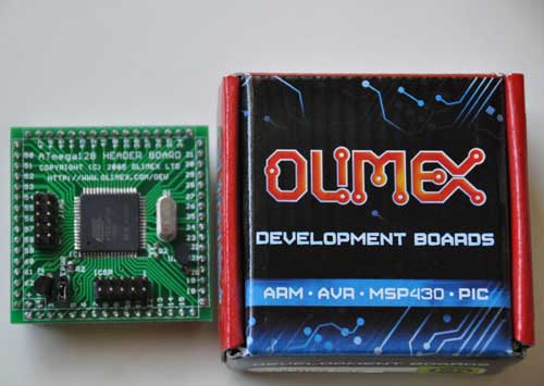
The AT90CAN128 header board is from Olimex, and comes in a cute little box:
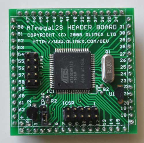
Here’s a closeup of the front:
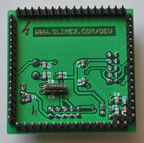
and the back:
I decided to try to get this board working with Arduino, since it’s a lot easier to set up than WinAVR. The first problem to solve is how to adapt the Arduino IDE to work with the AT90CAN128 and my USBtinyISP. After much Googling, I found SuperCow had already done the dirty work and posted it to the Arduino forum. He packaged the core files, bootloader, and a couple of examples into a handy zip file (which has since been taken offline). Since he used an unknown JTAG programmer, I had to adapt his files to work with the USBtinyISP and JTAG ICE mk1. Also, I modified them to work with Arduino 1.x+.
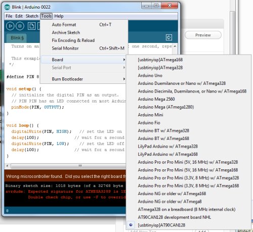
You can download the latest version from github: https://github.com/lincomatic/AT90CAN To install it, simply unzip the atcan90 directory into <your arduino directory>/hardware/at90can. Next time you restart Arduino, you can select it from Tools->Board->[usbtinyisp]AT90CAN128.
If you have a JTAG ICE mk1 programmer instead, select [JTAG ICE mk1]AT90CAN128.
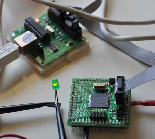
I connected up my USBtinyISP via the 10-pin ICSP header, burned the Blink sketch, hooked up an LED, and bingo! It’s working flawlessly.
In at90can/cores/at90can, I found can_lib.h and can_lib.cpp, which appear to be all we need to interface to the CAN bus. Since I currently know ZERO about CAN bus, I have a lot of reading to do before I can commence programming. SuperCow’s original zip file contains a couple of rudimentary examples.
Before I start programming, I need to build a little interface board containing the MCP2551 CAN bus transceiver, which should arrive next week. I already have an OBD-II cable to tap into the Leaf CAN bus via the OBD-II connector. Currently, obdcables.com is having a special on the 9-ft model.
Downloads: https://github.com/lincomatic/AT90CAN
Next: AVR CAN Bus Project – Step 2: Programming Low Fuse
