LeafCAN v2 Firmware in Alpha Test

I have been working on v2 of the LeafCAN firmware, which adds a whole slew of new screens, selectable via a rotary encoder.  The rotary encoder is connected to the AD0/1/2 pins on the expansion header of the LeafCAN V2 hardware.  The code is currently in alpha testing, and is available in the development branch of the LeafCAN github repository.  Be aware that the development branch is for my bleeding edge code, and at any time, the code there may be broken, as I continually checkpoint my code.  I will move it to the master branch when it’s ready to be released.

While I was developing the LeafCAN v2 firmware, I received a pleasant surprise in the mail from Barbouri (GregC) of the MyNissanLeaf forum.  He designed a PCB with 16×2 OLED display + RGB Led Rotary Encoder support,

v2o

and sent me a completely assembled and tested rig.  I immediately added support for this new hardware variant into my working LeafCAN v2 firmware code.  The RGB knob is cool:
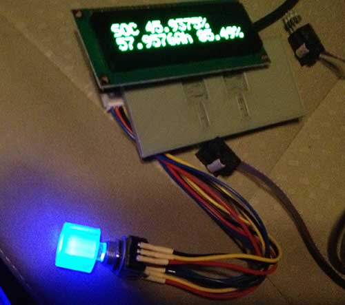
encoderled

but I am still pondering how best to use it. Currently, I have it blue when the car is idle, red when it’s consuming power, and green during regen.
Below is an overview of LeafCAN v2Alpha3. The various screens are selected by rotating the encoder knob. Some of the screens have different modes, selected via a press of the encoder knob. The first screen is the familiar info screen from LeafCAN v1.3:

mainscreen

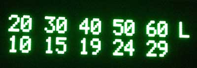
The top line from left to right is: kWh remaining/gids/fixed fuel bars, and the bottom line is: pack voltage/SOC%/instantaneous kW. The next screen is an idea lifted from Turbo3’s WattsLeft, the DTE (distance to event) screen:

dtel

The top line shows various miles/kWh values, 2.0/3.0/4.0/5.0/6.0, and bottom line shows the distance in miles to the event, in this case, Low Battery.  Pressing the encoder button switches it to miles until Very Low Battery:

dtev

and pressing the button a third time shows miles until Turtle:

dtet

Thanks to a breakthrough in active can sampling, spearheaded by GregH and TickTock, I was able to implement the following new screens. The first one has on the top line, High Precision State of Charge (SOC)%.  The bottom line shows State of Charge (Ah), and possibly a Battery Health %.

soccap

The next screen shows the 4 battery pack temperature sensors:

batttemp

The units are selectable between Celcius and Fahrenheit with a press of the button. Finally, the last screen shows the minimum and maximum cell-pair voltages in mV, as well as their difference:

cellvolt

When an OLED is installed, the display now blanks after 5 sec of inactivity on the CAN bus. Pressing and holding the knob for a second wakes the display up for 5 sec.  When an LCD is installed, the press/hold turns on the backlight for 5 sec, instead.

I will be working towards finishing LeafCAN v2.0 in the coming weeks, and will announce its release here.

Barbouri and I are also collaborating on a dual-CAN bus version of the LeafCAN hardware, which will be able to monitor the Car-CAN as well as the EV-CAN on the Nissan Leaf. This will open up access to various information which is accessible only via the Car-CAN, such as friction brake actuation, steering angle, etc.

I would also like to point out that GregH has yet another cool Leaf CAN bus dash display in the works (only $80) that is worth checking out. Also, TickTock and garygid are working on the very fancy dual-touchscreen open-source CANary Project. Turbo3 has also figured out how to extract data from the Leaf Car-CAN using a cheap ELM-327 clone dongle and an Android phone. There is currently a flurry of CAN bus hacking on the Leaf.
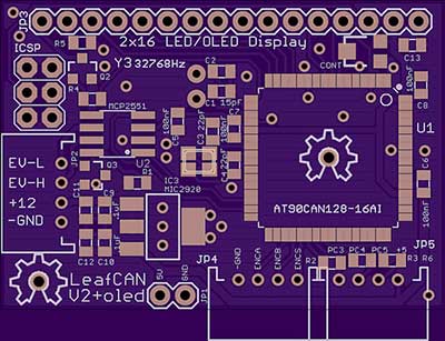
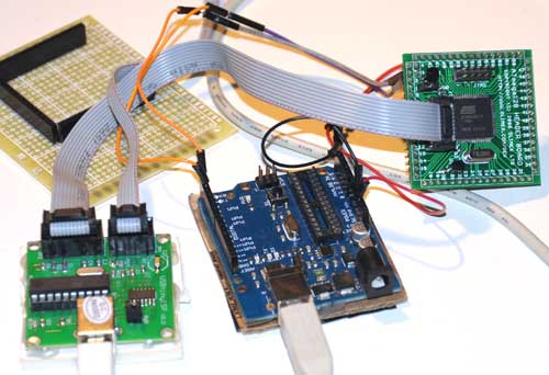
AT90CAN Support for Arduino 1.0+

I have adapted the Arduino AT90CANxx support to work with Arduino 1.0+. Also, I have moved the code to github, so that it will be easier to update.  Note that the Arduino 1.0+ support is currently only alpha quality.  I have compiled a few sketches, but I also have found some which currently can’t compile.

You can always download the latest version at https://github.com/lincomatic/AT90CAN

It is easiest to download the whole repository as a zip file: https://github.com/lincomatic/AT90CAN/zipball/master

Follow the instructions in the README file.  For more information, see the post linked below.

Related Post: AVR CAN Bus Project – Step 1: Programming AT90CAN128 with Arduino

Cheap 16×2 LCD Comparison

HD44780-compatible 16×2 LCD’s are cheap (<$4), and easy to use with Arduino via the LiquidCrystal library. To reduce the pin count considerably, the Adafruit LCD backpack is a nice little add-on that converts them to work via a two-wire I2C or SPI interface.

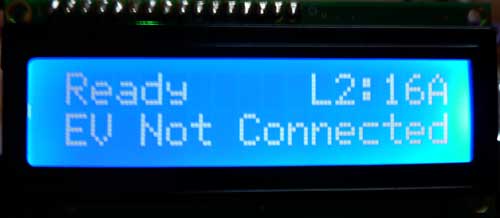
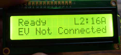
I bought two types to compare for use with OpenEVSE and LeafCAN. One has white lettering over a blue background, and the other one has black lettering over a yellow background. Here is an indoor comparison:

My camera can’t take good photos of the blue LCD indoors. The blue background is actually a good bit darker than in the photo, and the contrast is much better than it appears. Factoring that in, I guess I would still give the yellow LCD a slight edge indoors.

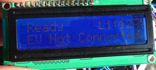
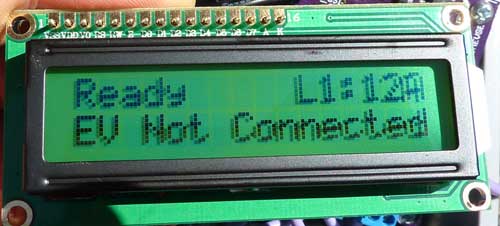
Now, here they are outdoors, in direct sunlight:

Again, the blue LCD didn’t photograph well. It looked slightly better than depicted in the photo. However, it’s a clear win for the yellow LCD. It works as a reflective LCD in direct sunlight, with very high contrast.

Case Protoype for LeafCAN

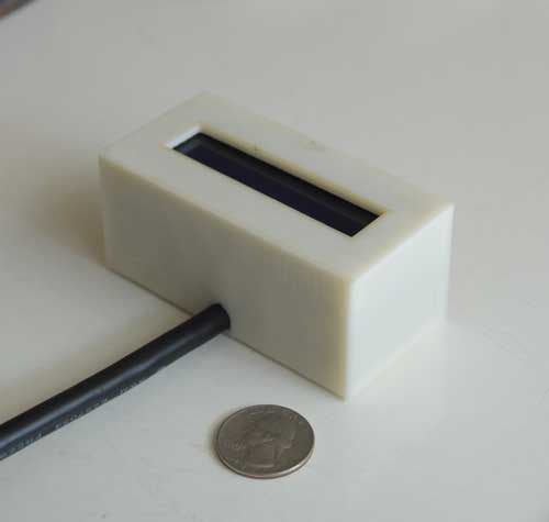
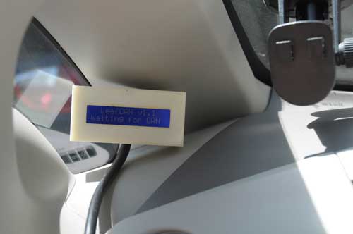
I’ve been having a lot of issues tweaking my latest Reprap design, so I haven’t been able print a case for my LeafCAN SOC meter.  Late last week, the printer was stabilizing, so I took a break to whip up something in OpenSCAD.  It’s just a basic box, which I printed in natural ABS.  I don’t like the sharp corners, so I’ve already redesigned it with rounded corners for the next rev.  This print was just to test out initial fitment.  This case is the absolutely smallest you can go, and still fit in all the electronics.
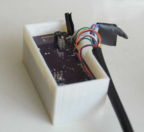
As you can see from the photo below, the header pins add considerable depth.

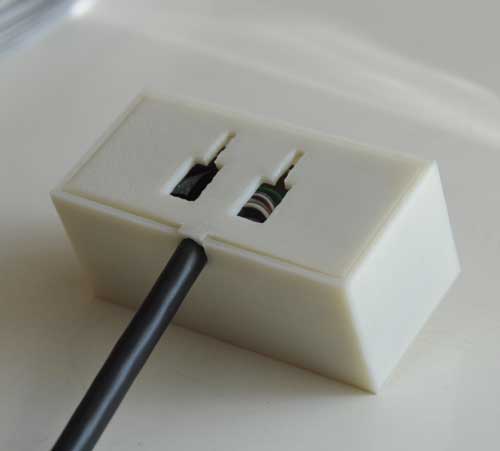
Also, in this build, I used female header pins to make the LCD detachable from the PCB, which added another centimeter to the depth of the case. The back has slots to engage various mounts:

Below, LeafCAN is clipped onto a suction cup mount, using the attachment slots:
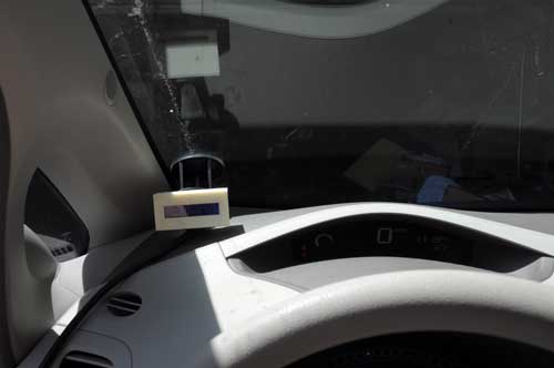
One idea I have is to make vent clips, so allow it to be attached to either the center or left HVAC vents.  But so far, my favorite position is inside the left corner window:

In the location above, it’s up high enough to see easily, without obstructing the view out the windowshield, and the A-pillar helps to shield it from the sun.  The only problem is figuring out the mount.  I’m going to try a print a holder to allow me to suction cup it to the corner window next.

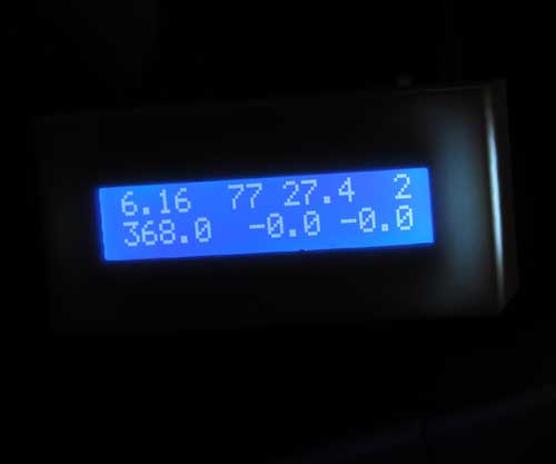
The natural ABS gives it a cool glow at night.  The photo below only shows the glow on the right, but it actually glows all around.

Although my vision is good enough that I can read the LCD comfortably, even in bright sunlight, I can understand how some people would find it hard to read.  I’m going to look into other displays, but at about $8, these 16×2 LCDs are hard to beat.

AVR CAN Bus Project: LeafCAN v1.2 Released

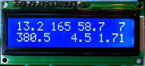
Another tweak today, I added instantaneous battery power consumption in KWh to the second line of the display. In order to make room, I had to do away with the V and A characters after the voltage and current draw. Here is the new display:

The top line, from left to right, contains Battery Pack Remaining KWh, SOC (“GIDs”), SOC % (GIDs/281*100), and Remaining Fuel Bars.
The bottom line now contains Battery Pack Voltage, Battery Pack Current Draw (Amps), and Battery Power Consumption (Pack Voltage * Pack Amps).

For users who prefer the old display, I added:

#define SHOW_KWH
#define SHOW_KW

If you comment out both lines, the display will be the same as v1.0, but with the smoothing that was added in v1.1.

As usual can download the latest release from github: https://github.com/lincomatic/LeafCAN/downloads.

Previous: AVR CAN Bus Project: LeafCAN v1.1 Released

AVR CAN Bus Project: LeafCAN v1.1 Released

I made some minor modifications to LeafCAN firmware today. First, I added display of remaining KWh in the battery pack, based on Phil Sadow’s formula of GIDs * 80 = Wh. Also, the display was a bit blurry when the values were updating rapidly, so I slowed down the refresh rate of the LCD to 250ms.

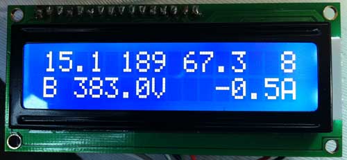
In order to make space for the KWh remaining value, I had to take out the % character in the SOC % display. Here is the new display:

The top line, from left to right, contains Battery Pack Remaining KWh, SOC (“GIDs”), SOC % (GIDs/281*100), and Remaining Fuel Bars.
The bottom line is unchanged, and contains Battery Pack Voltage, Battery Pack Current Draw (Amps).

You can download the latest release from github: https://github.com/lincomatic/LeafCAN/downloads. Note that I have added LeafCAN.hex, a precompiled file, for those who don’t have a working Arduino setup for compiling the code.

Previous: AVR CAN Bus Project: Step 4 – LeafCAN: Nissan Leaf SOC Meter
Next: AVR CAN Bus Project: LeafCAN v1.2 Released

AVR CAN Bus Project: Step 4 – LeafCAN: Nissan Leaf SOC Meter

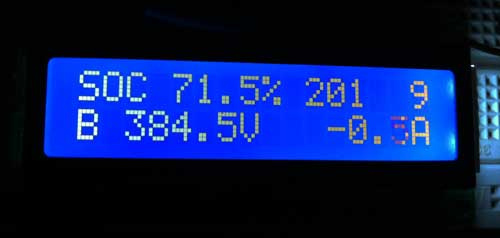
I have implemented a SOC (State of Charge) meter for the Nissan Leaf. Many thanks to garygid and others from the MyNissanLeaf forums, for their help in decoding the Leaf CAN bus messages, and figuring out the pinouts.

The top line shows the SOC%, raw SOC value, and number of charge bars displayed in the dash.
The second line shows battery pack voltage and current in amps.

You can download the Eagle CAD schematic and AVR (Arduino) code from github:  lincomatic / LeafCAN
The Eagle schematic uses the Sparkfun library.

The schematic shows how to implement the entire circuit, without using the Olimex AT90CAN128 breakout board.

My original intent was to make a small PCB that directly attached to the LCD, and put it into a small case, but I never got it past the breadboard stage.  Unfortunately, I have gotten busy with other projects, so I am probably not going to do further development on this device nor finish the PCB layout, unless there is a large amount of interest. However, feel free to adapt it as you wish for your own CAN bus projects. Do bear in mind, however, that the design is licensed via the GPL, so if you use it for a commercial project, you must openly share your design.

Previous: AVR CAN Bus Project – Step 3: CANspy CAN Bus Monitor
Next: LeafCAN v1.1 Released

AVR CAN Bus Project – Step 3: CANspy CAN Bus Monitor

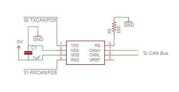
Sorry for the delay in posting the circuit and schematics from my AVR CAN Bus Project – Status Update 1.  The circuit for interfacing the Olimex AT90CAN128 Header Board is incredibly simple, and only requires 3 components.

Parts List
(1) .1uF ceramic capacitor
(1) 10K resistor
(1) Microchip MCP2551 CAN transceiver

Schematic

If you’re going to connect it to a Nissan Leaf, the car has 3 different CAN buses accessible via the OBD-II connector. The pinouts can be found on MyNissanLeaf.com in this thread: Leaf CANbus Decoding (Open Discussion)

To communicate with the AT90CAN128 header board from my PC, I connected a USB to serial converter to USART0: TXD0 (pin 3) and RXD0 (pin 2).

Arduino Sketch

Below is my CANSpy sketch for monitoring the CAN bus via the serial port, as depicted in my Status Update 1.

Download: CANspy.zip

To compile the sketch, follow the instructions in AVR CAN Bus Project – Step 1: Programming AT90CAN128 with Arduino.

In my next update, I’ll show how to implement a SOC (State of Charge) meter for the Leaf using a LCD display.
Previous: AVR CAN Bus Project – Status Update 1
Next: AVR CAN Bus Project: Step 4 – Nissan Leaf SOC Meter

AVR CAN Bus Project – Status Update 1

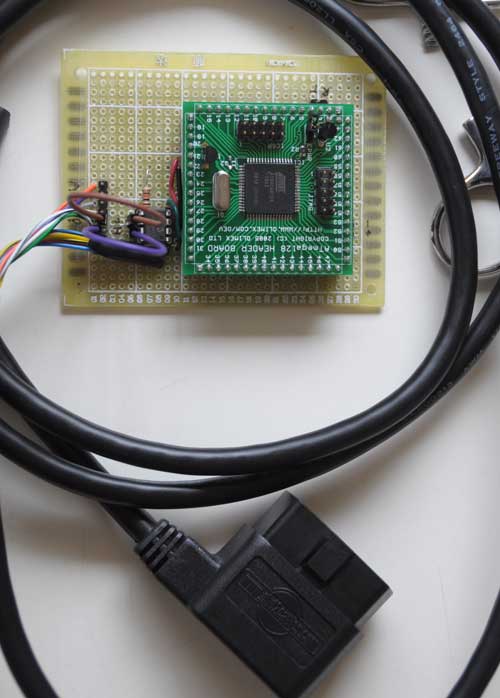
I got the circuit wired up yesterday:

The 6-pin jumper on the left lets me select one of the 3 CAN buses on the Nissan Leaf accessible via the OBD-II connector.

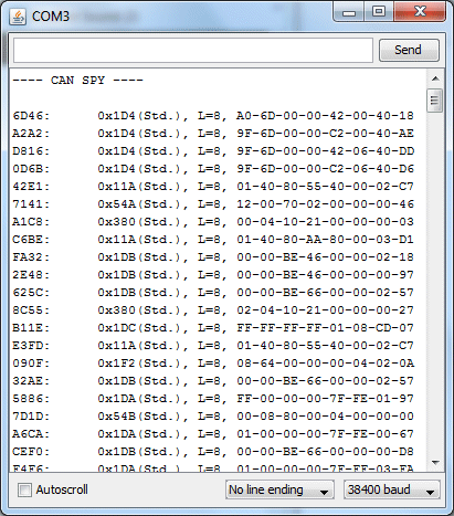
I hacked up some code quickly, and was pleasantly surprised that it actually worked! Woohoo! The part I thought was going to be most difficult – getting the CAN interface firmware working – turned out to be the easiest. Here’s my first capture of live data from the EV CAN bus:

Schematic and source code will follow.

Previous: AVR CAN Bus Project – Step 2: Programming Low Fuse
Next: AVR CAN Bus Project – Step 3: CANSpy CAN Bus Monitor

AVR CAN Bus Project – Step 2: Programming Low Fuse

One of the basic functions that the CAN Bus project needs is to be able to communicate with a PC via a serial port.  For modern PC’s the most straightforward way is to connect the AT90CAN128 header board to the host via a Serial->USB converter.  The most common type is the ubiquitous FTDI Cable, which is a USB cable with an embedded FT232R chip inside. Since I have a couple of spare Arduinos, I like to just use the embedded FT232R in the Arduino, rather than investing in a FTDI cable.  To use an Arduino as a serial cable, simply remove the ATmega328P MCU, and then connect the the TxD, RxD, and GND pins between the Arduino and the external device.

The AT90CAN128 has two USART’s.  The first one, on pins RXD0(2) and TXD0(3), is accessed via the Serial object in Arduino.  The second one, on pins RXD1(27) and TXD1(28), is accessed via the Serial1 object in Arduino.

To test serial communications with the host PC, I connected the first USART to the Arduino board with MCU removed as follows:

AT90CAN128 RXD0 pin 2 -> Arduino Digital 0 (RX)
AT90CAN128 TXD0 pin 3 -> Arduino Digital 1 (TX)
AT90CAN128 GND pin 53 -> Arduino GND

Then I wrote a quick sketch to simply read characters from USART0 and echo them back to the PC:

void setup()
{
Serial.begin(38400);
}

void loop()
{
while (Serial.available()) {
int c = Serial.read();
Serial.write(c);
}

To instead test the 2nd USART, substitute RXD1 for RXD0, TXD1 for TXD0, and Serial1 for Serial.

After burning the sketch, I simply opened the Arduino Serial Monitor, and typed characters to test the connection.  Much to my chagrin, the AT90CAN128 was echoing garbage back to the host.  I spent hours trying various things, checking and rechecking my wiring, to no avail.  I started to suspect that maybe the at90can files I got from SuperCow were inproperly configured.  One thing that raised this suspicion is that I found that the delay() function was running much slower than it should.  User evnow of the MyNissanLeaf forum pointed me to a HEX file of a similar serial echo program that Olimex posted on their site for the AVR-CAN board.  I burned the file into the AT90CAN128 using avrdude:

avrdude -c usbtiny -p at90can128 -U flash:w:avr-can_UART.hex

Once again, the board was corrupting the serial data.  This test showed that the culprit probably wasn’t SuperCow’s at90can files, since this hex file has been tested and working by other users.

Finally, it dawned on me that perhaps the fuses weren’t properly programmed.  I got a crash course on fuses from Adafruit’s avrdude tutorial.  Adfruit’s tutorial also linked to a great AVR fuse calculator.  First, I read out the fuses to 3 files:

avrdude -c usbtiny -p at90can128 -U lfuse:r:lfuse:h
avrdude -c usbtiny -p at90can128 -U hfuse:r:hfuse:h
avrdude -c usbtiny -p at90can128 -U efuse:r:efuse:h

The 3 commands above read the low, high, and extended fuses respectively, and output them as text files lfuse, hfuse, and efuse.  I found that the values were lfuse=0x4f, hfuse=0x19, efuse=0xff.  Using the Embedded Atmel AVR Fuse Calculator, I noticed that when lfuse=0x4f, that CKDIV8 (Clock divide by 8)  is enabled.  This didn’t seem right, and might account for the fact that the delay() function seemed to be running about 8x too slow.  Not knowing much about fuses, I decided to just use the value that Arduino uses for the ATmega328P, lfuse=0xFF, which turns off CKDIV8.

avrdude -c usbtiny -p at90can128 -U lfuse:w:0xFF:m

Bingo!  No more corrupted serial data, and the delay() function now runs at normal speed.  I have a feeling I’ll have to play with the other fuse bits at a later date, but since the board is working OK I’ll leave them be for now.  If you want to copy all of my current fuse settings, use this command:

avrdude -c usbtiny -p at90can128 -U lfuse:w:0xFF:m -Uhfuse:w:0x1F:m -U efuse:w:0xFF:m

Previous:  AVR CAN Bus Project – Step 1: Programming AT90CAN128 with Arduino
Next: AVR CAN Bus Project – Status Update 1