I have a Panasonic EP1004 massage chair that’s about 14.5 years old.
For the past several years, it has had problems getting going. When I tried to use it, the motors would spin for a while, but there would be no motion, and after a while, it would beep 3 times, and then stop. I would then have to power cycle it, and try again over and over. After several tries, it would finally start working. Over time, it took longer and longer to get it working. Finally, it became impossible to get it going. I searched the internet, and found the service manual for it.
Unfortunately, the manual didn’t really help me diagnose the problem, but I figured out that the massage and up/down clutches had gone bad. The clutches were expensive, and were unavailable for purchase anywhere. I figured out how to repair them without spending a cent! The step by step procedure is documented below.
To do the repair, you will need the following:
- Philips screwdriver
- 10mm socket wrench
- x-acto knife
- pliers
- a sheet of plastic
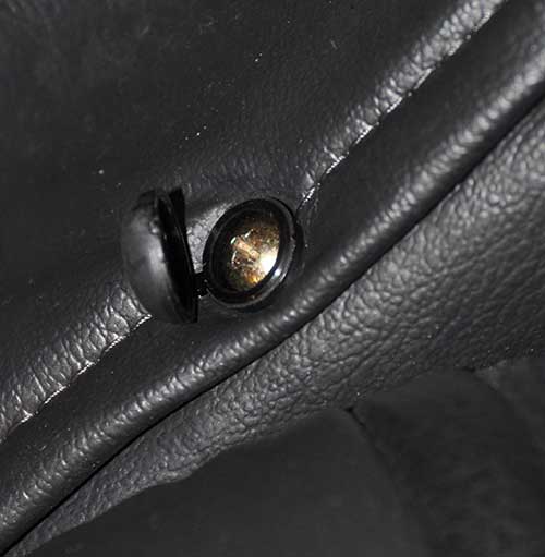
First, remove the screws which hold the back cover on. They are covered by plastic caps, which must be pried open to expose the Philips screw head:
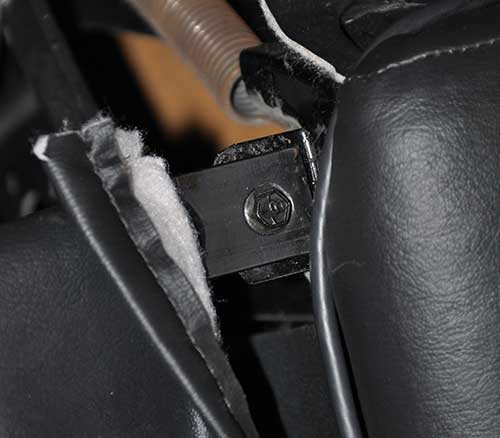
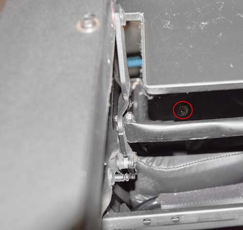
Next, remove the two 10mm bolts attached to the metal bar at the bottom of the cover:
Here is a close-up of one of the bolts:
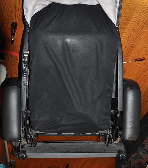
After flipping the outer cover out of the way, you will find a stretchy fabric cover below it.
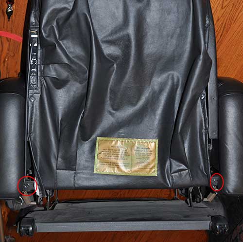
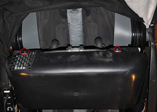
To remove the fabric inner cover, flip the chair over, and look for two Philips screws at the circled positions:
Circled in red below is a close-up of one of them:
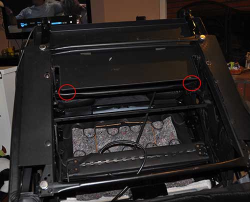
After removing the screws, the inner fabric cover can easily be lifted out of the way, revealing the motor and control assembly. Remove the two Philips screws at the top of the black plastic cover, and remove it:
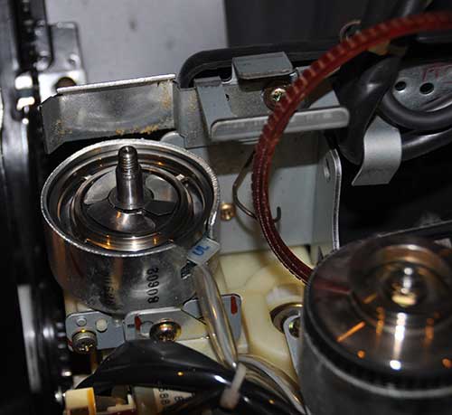
Inside, you will find the controller. I have labeled the clutches which were faulty in my chair:
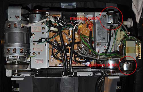
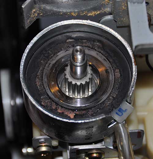
There are 3 other clutches, which you can find by looking at the diagram in the service manual. Fortunately, I was having problems with only two of them. We are not going to remove the clutches. Fortunately, the drive pulleys can be removed without taking the clutches out. First, remove the 10mm nut that secures the pulley:
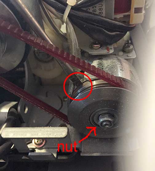
It is difficult to get the nut loose, because turning the nut also rotates the driven shaft. To keep the driven shaft from rotating when you turn the nut, jam a thin flat-bladed screwdriver between the two clutch plates, as shown in the photo above. A commenter below suggests that a bit of WD-40 may help, but be extremely careful if you try that… if it gets on the friction surface of the pulley, it will make your belt slip, or even eat your belt over time.
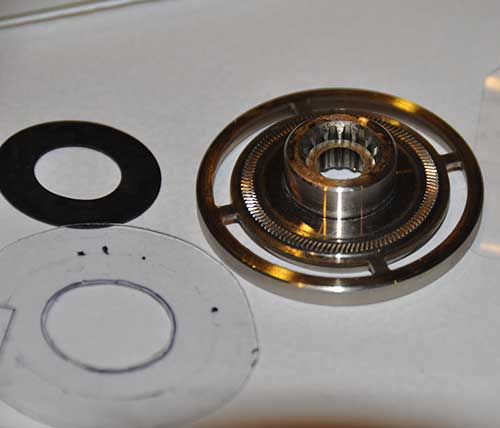
After you remove the pulley, you will find 4 parts: 1) a spring steel disk, 2) a rubber washer under it, 3) a small metal washer under that, and 4) the clutch plate below it. Make note of the layout of the parts as you remove them:
Here is the cuprit:
The clutches suffer from a basic design flaw. The rubber ring which serves as a noise damper for the clutch disintegrates over time, and becomes a sticky mess. It becomes so sticky that the clutch solenoid is too weak to overcome its grip, and can no longer drive the clutch plate into the pulley. Thus, the clutch plate can’t contact the pulley, and it just freewheels. Using the clutch plate as a template, cut out a ring of plastic as pictured below:
I used some hard plastic from some discarded packaging. I used scissors to cut the outline, and an x-acto knife to cut out the hole. Draw an outline around a US nickel to get a nice, round hole. Next, slide the plastic donut over the clutch plate:
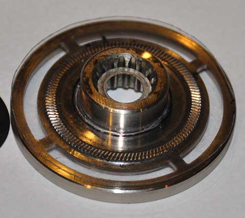
What the plastic does is keep the sticky black goo from touching the clutch plate, so that the solenoid can move it up and down. Note: Even though the clutch plate has teeth in it, these teeth are on the bottom, and they are not deep enough to dig into the plastic disc that we are adding. The friction that the clutch uses to drive the pulley is between the other side of the clutch plate, and the flywheel, which is the inner face of the pulley. The only purpose for the plastic disc we are adding is to keep the black goo from sticking to the bottom of the clutch plate. Try use a thin piece of hard plastic, as I did. Do not try to substitute a thicker piece of rubber… we don’t want any friction on between the bottom side of the clutch plate and the clutch body. Assembly is the reverse of the disassembly process.
When disassembling the massage clutch, you find find that the metal plate that holds the control box cover gets in the way. Carefully bend it out of the way with a pair of large pliers just enough so that the pulley can be removed. After reassembling the massage clutch, bend the metal plate back into the original position.
Another issue which could cause your chair to stop working is loose or broken belts. Check all of the belts for proper tension. My shiatsu massage rollers were also squeaking when I put a lot of pressure on them. This was because the lower left belt was stretched, and was quite loose. Unfortunately, even after loosening the motor mount screws and sliding the motor as far left as the adjustment slots would allow, the belt was still too loose. I ended up using a large screwdriver to just bend the motor mounts outwards a little bit to tighten up the belt. [UPDATE: This eventually failed, and the belt got loose again… see Part 2.]
Reassemble the rest of the chair by following the disassembly steps in reverse. Voila, your Panasonic massage chair is good as new again!
Downloads:
Panasonic EP1004 Service Manual
Panasonic EP578 Service Manual
Panasonic EP1010 Service Manual
EP1005 Operating Instructions
EP1004,1005 Simplified Service Manual
Next related article: How to Repair a Panasonic Massage Chair, Part 2
 The notable differences in the EKitsZone Rev.3 versus the Arduino UNO R3 are: