I bought 100 diffused 5mm RGB LED’s on eBay for my upcoming project, an 8×8 RGB matrix. I was extremely impressed by the fast (free) shipping – 7 days, all the way from China! Much to my chagrin, when I started testing them, I found that the vendor had sent me common cathode, rather than the common anode LED’s that I had been expecting. This is a big setback for me, because I was going to use them with the Colorduino that ITead Studio is graciously sending me for beta testing. The Colorduino expects common anode LED’s, so now I have a pile of 100 useless LED’s. Nevertheless, I decided to test them out to find out their brightness, color mixing, and diffusion characteristics.
Andy Rapp has posted a handy setup for testing RGB LED’s on his blog. He wrote a Java program and Arduino sketch, which allows you to interactively control an RGB LED with a host PC. I downloaded his code, and had it running very quickly.
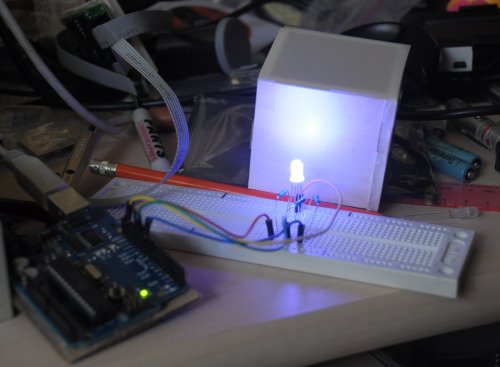
I also built a little 2x2x2 foam box, and put a piece of Grafix .005″ thick matte drafting film on top of it. The LED works fairly well. I’m satisfied with how well the combination diffuses the light.
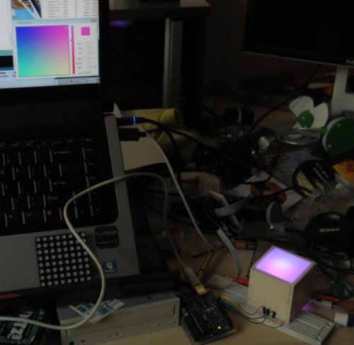
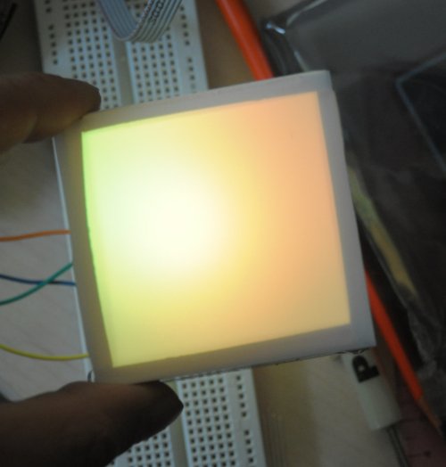
Andy’s Java app puts up a color picker on the host computer screen, which lets you interactively test out different colors in realtime. You can see the color picker in the bottom right corner of my computer screen. The brightness of a single LED is better than I was expecting, but the color mixing is not. It’s hard to see in the photos, but the red/green/blue components don’t mix that well, and the individual colors are brighter in certain areas. In the photo above, notice how one side of the box is more purple, and the other side is more magenta. This makes it impossible to get a decent approximation of white, even when you compensate for the fact that the 3 colors differ quite a bit in brightness when the same current is passed through them. Below are some more shots. In the yellow shot, I’m raising the box up so that the LED is lined up with the bottom of the box. This makes the light noticeably smoother looking. Note how the light is not centered in the box, even though I have the LED pointing perfectly vertical. I may have to make minor adjustments when I build the real matrix.
It looks bright enough that I may be able to get away with just using 1 LED per cell. I’ll have to see when I get the correct common anode LED’s and the Colorduino to play with.
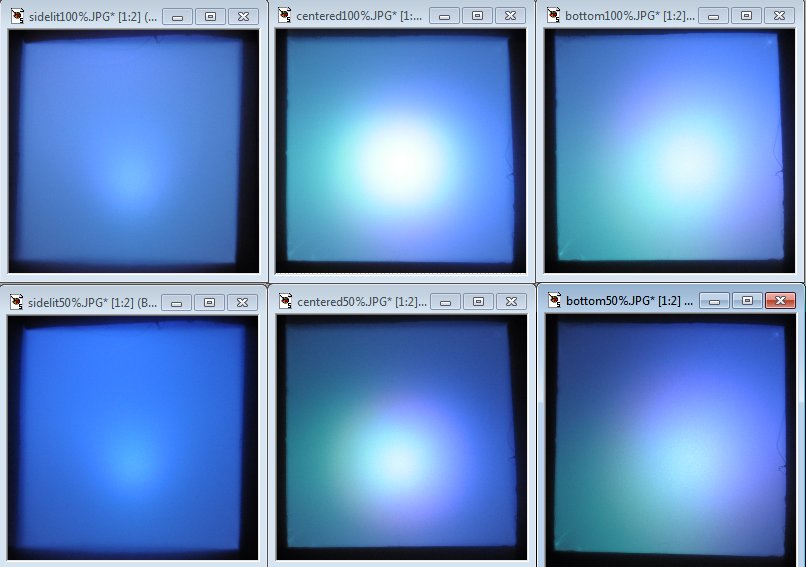
UPDATE: I did some more testing. In the photo below, the top row is @ 100% brightness, and the bottom row is @ 50% brightness. In the left column (“sidelit”), the LED is centered in the box, but pointing to one of the walls (so the view of the LED through the hole is the side of the LED). In the center column (“centered”), the LED is pointing straight at the and is physically centered in the box. In the right column (bottom), the LED is pointing straight at the drafting film, but aligned w/ the bottom of the box. As you can see, the “sidelit” setup has the best color mixing and is the most even in brightness. The “centered” setup is brightest, but has the biggest hot spot, and the colors don’t mix as well. The “bottom” setup is a bit more even in brightness, but still suffers from uneven color mixing. I’m still undecided about which way to go. What I like about the “sidelit” setup is that it enables the option of making a free-standing matrix that lights up two sides instead of just one. I guess I’ll have to put off the decision making until I get the Colorduino and the common anode LED’s. I contacted the eBay vendor this afternoon, and he says he’ll rush out the common anode LED’s tomorrow. Hopefully, they will arrive in a week.


