WS2812B LED (NeoPixel) Control: Part 2 – WiFi Control via Art-Net on ESP8266

INTRODUCTION

For wireless control of WS2812B (NeoPixel) LEDs, I initially played with Bluetooth SPP (Serial Port Profile), due to the simplicity of setting up the host software… from the host’s software’s point of view, the connection just looks like a physical serial port. Unfortunately, the flakiness of my Windows 8.1 PCs’ Bluetooth SPP support caused me to abandon that solution.

WIFI CONTROLLER HARDWARE

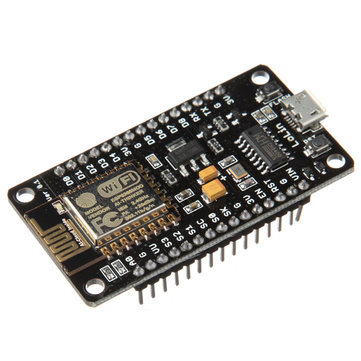
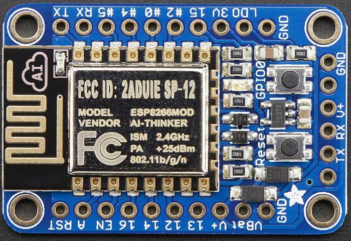
ESP8266 modules provide a very low cost method of interfacing WS2812Bs to WiFi. Adafruit’s Huzzah module costs $9.95, but on eBay, NodeMCU clones, such as the LoLin NodeMCU board can be had for ~$3 shipped from China. This makes it even cheaper than the Arduino/Bluetooth combination!

What’s more, the LoLin board has a CH340G onboard, so it doesn’t require a FTDI cable to connect it to your host computer for programming. I ordered a few of the LoLin boards, but in the meantime, I started playing with the Adafruit Huzzah boards I had on hand.

With the addition of ESP8266 support via the Board Manager, Arduino becomes an easy to use platform for code development. Also, there are easily obtainable libraries for both WiFi configuration and control of the WS2812Bs.

One extra complexity of using an ESP8266 to control WS2812Bs is that the ESP8266 is a 3.3V device, while the WS2812B is a 5V device, (usually) necessitating level shifting. The WS2812B datasheet shows a threshold of >= 0.7VDD for logic HIGH, and <= 0.3VDD for logic LOW. The allowed VDD ranges from +3.5-5.3V. Interestingly, some WS2812Bs can actually work when powered by 3.3V, and driven by 3.3V logic, even though it’s out of spec, but many cannot. On the other hand, it’s totally within spec to be powered by 3.7V and driven by 3.3V logic. So, if you use a 3.7V LiPo battery to power the WS2812B strand, the WS2812B data line can be connected directly to the ESP8266 without any level shifting! If you choose to go this route, power the Huzzah from its VBat terminal, so that the 3.7V will be regulated down to 3.3V to power the ESP8266. More details are available in Adafruit’s NeoPixel Uber Guide.

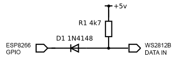
Since I want to be able to drive long strands of LEDs, I elected to go the 5V power with level shifter route. Also, I have lots of 5V power supplies laying around. There are many different ways to do level shifting, either passive or active. The WS2812B has tight timing requirements, and runs at 800KHz, so care has to be taken in order to avoid signal distortion. One of the most reliable methods is to use a 74AHCT125 level shifter IC. I decided to first try a simple diode and pullup resistor circuit (credit: RPi GPIO Interface Circuits):

The circuit is currently working flawlessly for me, driving my 5m long strand of 150 LEDs.

WIFI COMMUNICATION PROTOCOL

In order to send data to our WS2812Bs over WiFi, we need some sort of IP protocol. Art-Net is a royalty-free protocol, which sends DMX data embedded in UDP packets. I decided to go with Art-Net because it is an industry standard that is supported by a variety of Pro software, and Jinx! and Glediator can talk to it.

ARDUINO FIRMWARE

I will not go into how to set up Arduino to compile sketches for the ESP8266, as that is discussed elsewhere. To compile for the Huzzah, select it as the compile target from the Tools pulldown menu:

Tools -> Board -> Adafruit HUZZAH ESP8266

I created a sketch, which is a mashup of a few different projects from github. The code is in my github repo: WS2812ArtNet. I stripped the Adafruit NeoPixel library down to the bare metal, and added a captive portal for configuring the WiFi connection. Also, it supports a hardware pin to erase the WiFi settings. Configuration is done via a few defines in WS2812ArtNet.ino. See the #defines for PIXEL_CNT, PIN_DATA, PIN_LED, and PIN_FACTORY_RESET. At a minimum, PIXEL_CNT must be set to the number of LEDs in your strand.

PIN_DATA is used to select the pin that’s used to drive the data to the LED strand.

PIN_LED is used to select the a pin which blinks an LED every time an Art-Net packet is received. This makes it easy to tell if the board is receiving data. In addition, the LED is initially off at boot-up, and turns solid red when the ESP8266 connects successfully to a WiFi AP. By default, PIN_LED = 0, which makes it control the onboard red LED on the Huzzah.

PIN_FACTORY_RESET wipes out any saved settings and clears the EEPROM when it’s grounded for 2 sec.

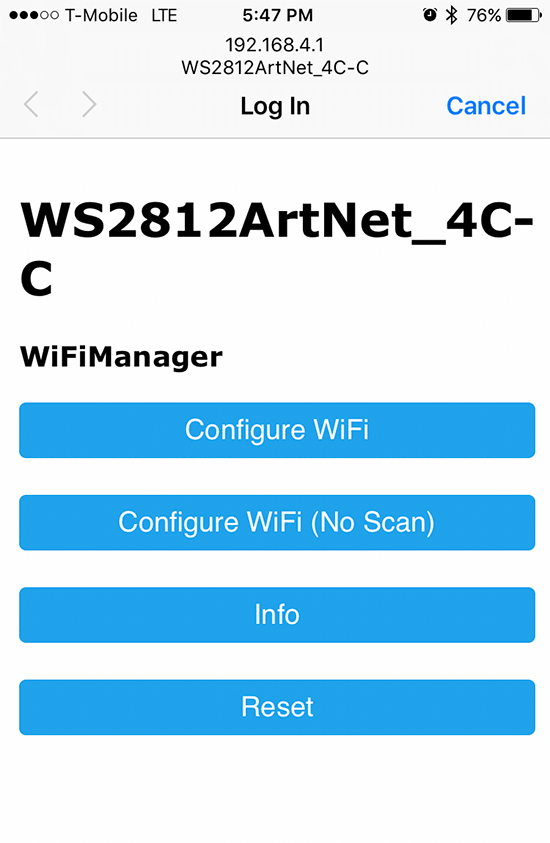
To load the WS2812ArtNet sketch into the ESP8266, first press the GPIO0 and Reset buttons simultaneously, and then let go of the Reset button. The red LED will then glow dimly, indicating that the bootloader is active. Once the sketch is loaded, when the ESP8266 initially boots up, it will create a WiFi AP with SSID WS2812ArtNet_hh-h. Use a computer, phone, etc to connect to the AP. Upon connection, it should automatically present a captive portal for configuration:

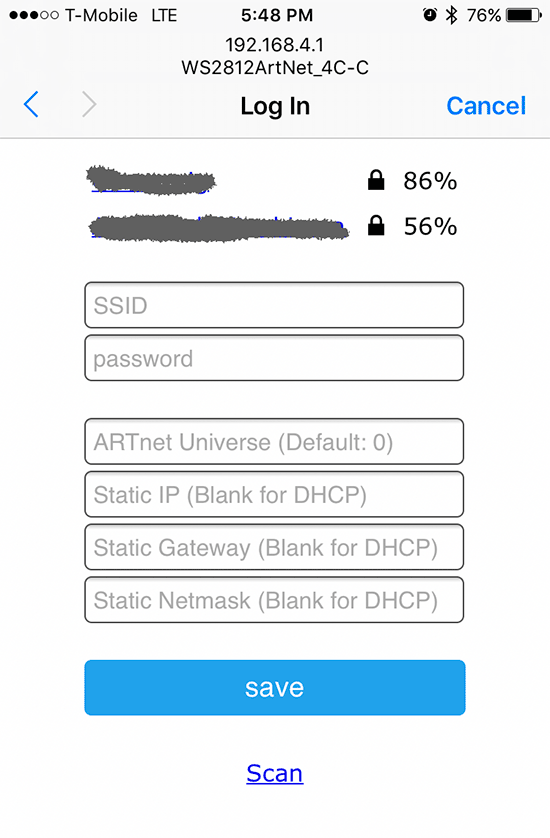
If the captive portal doesn’t automatically launch, open a web browser, and point it to http://192.168.4.1. Tap on Configure WiFi, and the ESP8266 will automatically scan for available APs:

Tap the desired AP’s SSID, and type in the passphrase. Additionally, you can also choose a starting Art-Net universe, and configure a static IP. After you tap save, the ESP8266 will reboot. If it connects successfully to your AP, the onboard red LED will light. Then, the LED strand will go into the startup test sequence of lighting up red, green, and blue, and then turning off. Once Art-Net data is received, the LED still start blinking with every packet it receives.  If you have trouble during setup, you can see debug messages by opening the ESP8266’s serial port in a terminal set to 115200,N,8,1.


When configuring Jinx!/Glediator, select GRB as the pixel data format.


Prev: WS2812B LED (NeoPixel) Control: Part 1 – Serial Control via 8-bit ATmega (Arduino)
WS2812B LED (NeoPixel) Control: Part 1 – Serial Control via 8-bit ATmega (Arduino)
INTRODUCTION

I’ve been laying the groundwork for doing some projects using remote controlled RGB LEDs. My first attempt was Lampduino, which used discrete RGB LEDs, and an ITEAD Colorduino as a controller. In that project, I ran into several pitfalls:

  • though inexpensive, assembly of the LED matrix was very labor intensive
  • the LED’s were rather dim, due to the limited drive capability of the Colorduino
  • the frame rate was slow, due to limited baud rate and RAM
  • while it was scalable, I didn’t like the idea of having to use a separate Colorduino for every 64 LEDs

A few years have passed, and WS2812B LEDs have dropped enough in price enough to get into the range that I feel is affordable. They can be found on eBay and AliExpress very cheaply. Also, they can be controlled without any specialized hardware – all that is needed is one GPIO pin. There are libraries available for many of the popular microcontrollers. Some examples are Arduino, ESP8266, Teensy 3.x, and Raspberry Pi.

HOST SOFTWARE

The other piece of the puzzle is control software. For Lampduino, I hacked uRaNGaTaNG’s mtXcontrol Processing sketch into rgbMtx, but I found Processing to be a very limiting platform, which was hard to debug. This time around, I found a couple of interesting free LED control programs, which are both quite powerful. The first one is Jinx! LED Matrix Control, which runs on Windows only, and the second is Glediator, which is a Java app. Both programs, while free, are not open source. However, they are both powerful enough to do some interesting things.

HARDWARE

I decided to start my experiments with an Arduino Pro Mini clone, because they have a tiny footprint, are cheap (clones are <$2 shipped from China on eBay), and I happened to have some laying around. Also, the Arduino Pro Mini’s ATmega 328P MCU runs at 5V, so no level shifting is required when interfacing to WS2812Bs. Glediator’s creator, Solderlab, has barebones, fast serial client Arduino sketch which can be downloaded at: WS2812-Glediator-Interface. It can run on any 8-bit ATmega-based Arduino such as the Mega, UNO, Deumilanove, etc. The code that outputs the data to the LEDs is written in assembly language, and is thus, very fast & compact. Also, rather than using Arduino’s Serial library, it contains its own very compact serial code. At the expense of a little bit of speed, I decided to generalize it a bit, and add my own packet protocol. My code is on github at: WS2812Remote. The main changes that I made in my version of the code are:

  • Since I didn’t understand the Glediator example’s serial code, I reverted to using Arduino’s built-in Serial library. I’ve tested it with baud rates up to 1000000 and an FTDI cable on a Windows PC, and it works fine
  • I added support for my own packet protocol. Glediator’s serial protocol is extremely simple. Each frame starts with 0x01, followed by the pixel data stream. My simple packet protocol adds an XOR check byte, as well as a few simple commands such as color fill and blanking of the LEDs.

I also wrote a C++ program, called pkt_test, which demonstrates usage of my packet protocol.

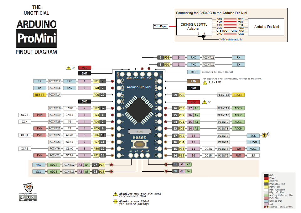
Hookup of the WS2812B LED strand to the Arduino is quite simple. You can use any 8-bit Arduino. First, you must select a data pin to drive the strand. I arbitrarily decided to use pin PD2. For speed and compactness, instead of using Arduino functions to access the data pin, the code refers to the ATmega port and pin numbers, rather than Arduino’s rather arbitrary digital pin numbers. On the Arduino Pro Mini, digital pin 2 = PD2, as can be seen from the following pin mapping diagram:

FIRMWARE CONFIGURATION

So WS2812Remote.h is configured as follows:

#define DATA_PORT PORTD
#define DATA_DDR DDRD
#define DATA_PIN 2

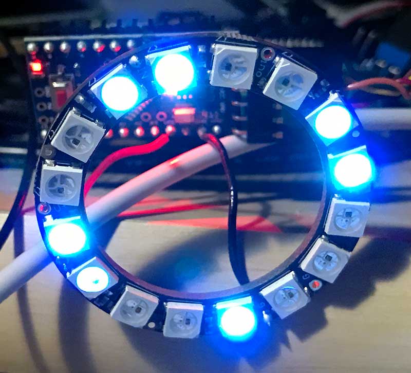
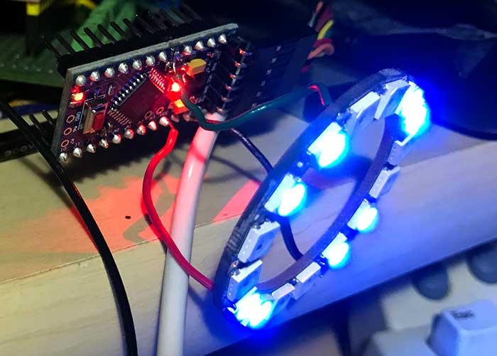
Next, PIXEL_CNT needs to be set to the number of LEDs in your strand. I tested with an Adafruit NeoPixel ring containing 16 LEDs:

#define PIXEL_CNT   16

Connect your the data input pin of the first LED of your WS2812B strand to your selected data pin. Adafruit recommends a 300-500 ohm inline resistor to protect from voltage spikes. The NeoPixel ring I used already has a resistor onboard, so I didn’t need it. I connected the +5V and GND pins directly to the corresponding pins on the Arduino. To protect against current inrush when powering it up, Adafruit also recommends connecting a 100uf capacitor between the +5V and GND pins. However, it’s not necessary if you’re just going to power it from USB, which is what I did, since I was only powering 16 LEDs. For large strands, you will need an external power supply to supply sufficient current, as each LED can draw up to 60mA at full brightness. If using an external power supply, make sure to always apply power to the WS2812B strand before the data pin!

HOST SOFTWARE CONFIGURATION

I used the same FTDI cable that I used for programming the Arduino as a virtual com port for sending data to it. When configuring Jinx! or Glediator, select Glediator protocol. For speed, the sketch just receives raw pixel data, and dumps it out to the LED strand, so the data format is in native GRB order.

When configuring Jinx! or Glediator, select Glediator as the device type (Jinx!) or output mode (Glediator). Make sure that the baud rate of the corresponding com port matches BAUD_RATE as defined in your sketch. I tested 115200 and 1000000 bps with my FTDI cable, and both worked fine with both programs. It failed at 1250000 bps.

If you want to play around with my packet protocol, the pkt_test code is self explanatory. I tested it with Visual Studio 2015 in Windows 8.1, and g++ in Debian linux 8.2.0. Prior to compilation, set COMM_PORT to correspond to your Arduino’s serial port. Also, confirm that BAUD_RATE in ../WS2812Remote.h matches the value that was used when loading the Arduino sketch. To compile and run pkt_test in linux, use:

g++ pkt_test.cpp serialib.cpp -o pkt_test
sudo ./pkt_test

WIRELESS CONTROL

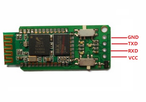
My first inclination for wireless control was to use Bluetooth, due to its simplicity. The Bluetooth SPP (Serial Port Profile) makes it easy to construct a wireless virtual serial interface between a host computer and the Arduino. This allows you to use exactly the same host software configuration that you would for a direct serial connection to the host. I had an Elechouse EHB Serial Bluetooth Module in my parts bin (very similar to the ubiquitous HC-05), so I decided to try it out.

Before using the EHB module can be used, it must be configured with a series of simple AT commands. I hooked it up to my Windows PC with my FTDI cable, and used PuTTY as a serial terminal to configure it. Connecting the EHB module to the Arduino is quite straightforward:

Arduino -> EHB

5v -> VCC
GND -> GND
RXD -> TXD
TXD -> RXD

Pairing the EHB to a host computer creates a virtual serial port for the host software to access. Unfortunately, I was using Windows 8.1 as my host computer, and its handling of Bluetooth SPP clients is rather flaky. Every time I powered down the LED controller, I had to unpair/pair the Bluetooth in order to get the virtual serial port to work properly. While it worked flawlessly when the virtual serial port was functional, ultimately, I abandoned Bluetooth due to the flakiness of Windows’ Bluetooth SPP support. Perhaps Linux can handle it better.

Next: WS2812B LED (NeoPixel) Control: Part 2 – WiFi Control via ARTnet on ESP8266

Lampduino – an 8×8 RGB Matrix Floor Lamp

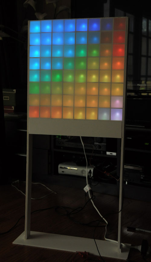
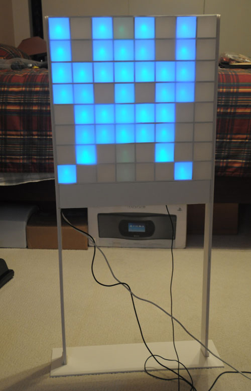
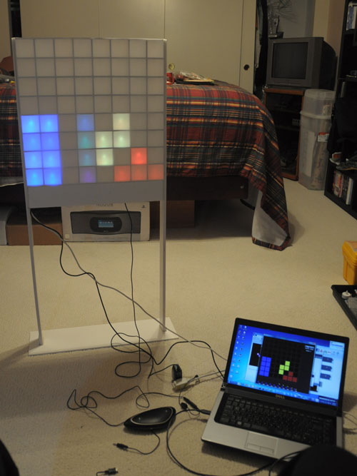
This past weekend, I finally finished building my 8×8 RGB matrix floor lamp.  I call it Lampduino.  A Processing sketch running on a host computer controls Lampduino via a USB connection.  When turned on without a computer, it automatically displays a soothing plasma simulation. If you want to build one of your own, I wrote a step by step Instructable:

Lampduino – an 8×8 RGB Matrix Floor Lamp


Space Invaders

Tetris

Related articles:

8×8 RGB LED Matrix Construction: Step 2 – Wiring

The first step in wiring up the matrix is deciding on the method.  I immediately ruled out soldering, because it’s messy, slow, and smelly.  Also, it incurs the risk of overheating the LED’s as well as being hard to repair.  I also ruled out using crimp-on connectors due to expense.  After pondering it for a while, I decided that wire wrap would be the best approach for several reasons:

  1. it’s cheap
  2. there are no toxic fumes
  3. there is no risk of overheating and destroying LED’s
  4. it’s easy to undo, so repairs are easier
  5. it’s relatively quick to do
  6. it’s as reliable as soldering – perhaps more reliable, since there’s no risk of cold-soldered joints
  7. the wire is so thin that it can be threaded into the gaps between the foam matrix pieces

The downside is the small wire gauge – 30AWG.   I was afraid that it might too small, so I consulted some tables on the Internet, I found that it has a resistance of 105.2 Ω/1000 ft. I estimated an upper bound of 4 ft of wire, so that’s ~.4Ω – probably insignificant for this application.  Next, I found that the current carrying ability (Ampacity) is estimated at .144A by most tables, but one actually had it listed at .86A.  The LED’s I’m using run at a maximum of 20mA per color.  In a column, a maximum of 1 LED at a time is lit, so it’s definitely in spec.  On the other hand, if a whole row is driven w/ the with all 3 colors lit, we can end up with 8 x 3 x 20mA = 480mA.  This is way over the .144A spec, but below the .86A spec.  I decided to just try it, and if I encountered problems, I would put multiple wires in parallel for the rows.

I already had a wire wrapping tool, which ,I bought many many years ago (ouch,they seem to have gotten expensive over the past 30 years! I think I spent $5 on mine), so all I needed was some wire.  Radio Shack carries 50 ft spools of red, white, and blue 30AWG kynar-insulated wire for 3.99 a roll (note:  the price seems to have increased to $4.19 in the 2 weeks since I bought mine).  I bought one roll of each.

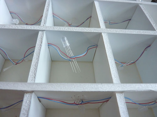
I started out wiring each color in sequence along an 8-LED chain, but later found that it’s more orderly to wrap the 3 wires (R/G/B) between each pair of LED’s at a time.  When I wrapped my first strand of 8 LED’s I didn’t pay attention to the orientation of the leads.  This made a mess.  It’s better if you orient the leads in the same direction as you wrap each chain (e.g. red pin to the left), rather than just doing it haphazardly.  This way, the wires don’t criss-cross each other as much.  After much experimenting, I found that a 4″ length of wire between each pair of LED’s was optimal for my 2″ ID matrix.  This left enough slack between the successive LED’s to work with.

I’m using common anode 5mm diffused RGB LED’s bought on eBay from a Chinese vendor… $25 for 100.  Not particularly cheap as eBay goes, but they use free  trackable EMS shipping, which takes about half the time as regular HK post.  The vendor sent me common cathode LED’s by mistake, so I had to wait for him to send me another batch w/ the right polarity.  The pins go from left to right in the photo, B-G-Anode-R.  The anode lead is longer, which makes it easier to identify.  Note that since the anode is for the rows, while the other R/G/B leads are for the columns, I didn’t wire it yet at this stage.  Here are the completed strands:

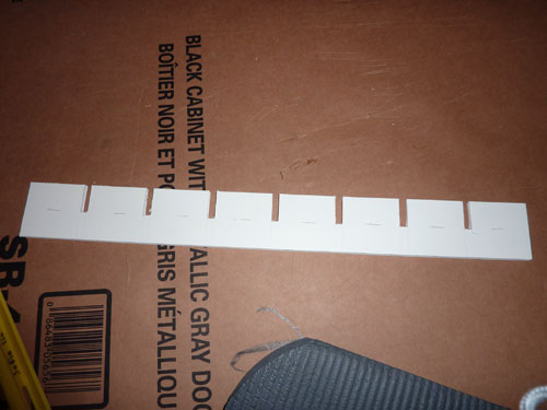
Since the LED’s will be face downwards in my matrix, my idea was to fasten them by simply poking the wires through the cardboard/foam sandwich.  I found that the paper was a bit too thick to do this easily, so I had to cut slots into the matrix pieces to receive each LED.  Be sure to do this before you thread the 8 LED strands into your matrix!

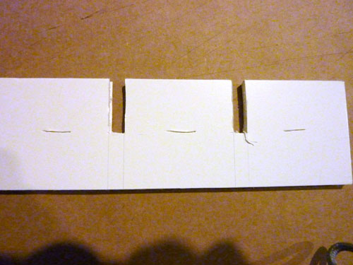
It’s hard to see the slits in the photo above.  Here is a close-up:

Make sure that you cut all the way through the foam sandwich.

After completing the 8 chains of 8 LED’s, the next step was to thread them into my matrix.  The wire wrapping wire is very thin, and easily fits into the interlocking slots of the matrix.

To wire up the rows, you need to flip over the matrix, so that you can wire and thread the row wires perpendicularly to the columns.

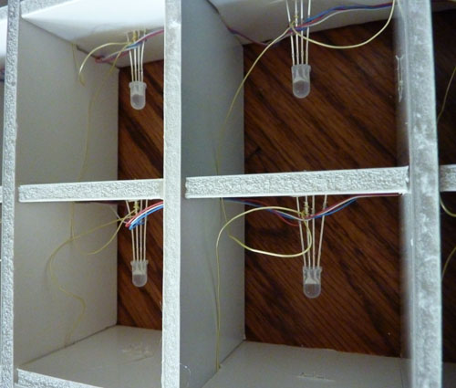
This step requires a bit more dexterity, because you have to work with the LED’s inside the matrix.  Thankfully, there are only 8 rows (as opposed to our 24 (8×3) columns, so there are a lot less wires to deal with.   In the photo above, notice how the I’ve flipped the matrix.  The RGB wires are threaded through the bottom slots, while the yellow anode wires are threaded perpendicularly, through the top slots.  Also, note how I’ve secured the LED by jamming it into the slot that I cut.  The gaps among the 4 leads on each individual LED are rather narrow, so it’s a good idea to spread the leads apart before plugging them into the matrix, to avoid shorts.  You might be wondering why I have the LED’s pointing sideways instead of straight up. This is because I am building a matrix which will stand up vertically, so that the light will come out both sides.  Also, in my previous experiments with LED orientation, I found that the colors didn’t mix very well when the LED’s were pointed directly at the viewer.As you can see, this setup made it considerably more difficult and time consuming to build than if I had wired them pointing upwards on a single sheet of poster board.

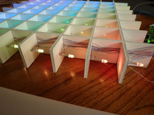
Here is how I routed the column wires:

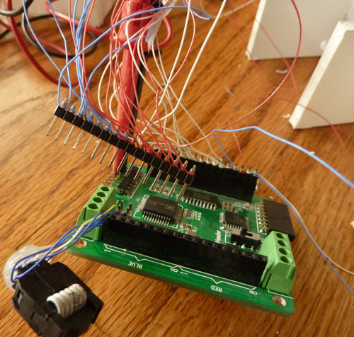
Finally, I wire-wrapped all the leads onto a pair of 16-pin male headers.  The pin groups are conveniently labeled on the Colorduino, so it’s easy to figure out which wires go where.

Even so, I managed to reverse all of the green wires; since I used wire-wrap, it was easy to undo them and hook them up in the correct order.  It’s a good idea to manually test all of the connections before plugging them into the Colorduino.  I used a 5V supply with a 100Ω resistor and test clips to check each individual LED.  Amazingly, I didn’t have any shorts.  After testing was completed, I used small blobs of hot glue to secure each LED, and in each interlocking corner of the matrix.

When I finally powered it up via my USBtinyISP, I found that my PC couldn’t communicate properly with the Colorduino.  The LED’s were drawing more current than the USBtinyISP could output.  Hooking the Colorduino up to my 5V 1A supply fixed that.

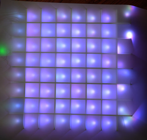
Here’s what it looks like with drafting film laid on top, and all the lights set to maximum brightness:

One very disappointing discovery is that I won’t be able to properly set the white balance on this matrix.  Note the wide range of color variation among the LED’s.  I guess the quality control is not so good when you buy cheap LED’s on eBay.  I had the same problem even with the white LED’s that I used in my 5×5 monochrome matrix.  Also, I don’t understand why the LED’s are making bright dots, since I was getting better diffusion in my initial experiments.  The LED’s I used in the experiments should have been very similar.. they were from the same vendor, but were the common cathode ones that he sent me by mistake.  I guess the new LED’s I received are not as diffuse as the last set he sent me.

Another discovery I made while testing is that the orientation of my wiring is wrong.  I had wanted the wiring to be routed such that the Colorduino would be on the bottom.  In fact, the Colorduino is positioned on the side.  Therefore, I’m going to have to swap the rows and columns in software – an easy fix.  I ran the matrix full brightness for a while, and the row wires aren’t melting or heating up, so the thankfully, the current carrying ability of the row wires is OK.

The wiring task was a grueling and tedious task.  I spent a total of about 16 hours spread across 4 days doing it.  Thank goodness for TV, or I would have gone insane.  Needless to say, I’m all caught up with the recordings on my DVR!  My hands ache, my back aches, my joints ache!  One annoying thing about 30AWG wire is that it’s so thin that it’s hard to get a grip on it, and when it falls on the floor, it’s hard to pinch it between your fingers to pick it up.  Wiring up the matrix required 256 wires (8x8x4), each wire needed to be stripped and wrapped on both ends… 512 joints to wrap!!  I really felt like I was losing my mind, and that I was going to go blind.  It has to have been the most tedious task I’ve ever completed!

The next step will be finishing up the matrix assembly.  I still haven’t gotten the outer frame onto it.

Related articles:

8×8 RGB LED Matrix Construction: Step 1 – Cutting Foam Board

I started building my 8×8 RGB LED matrix this weekend. The first step was mechanical construction of the matrix. Below are the materials I used:

I recycled a piece of foam core poster board. This kind of poster board is composed of two sheets of thick paper, with a piece of foam sandwiched in between. You should be able to find it in an office or art supply store. The dimensions of the board were 45x30x1/4″. The tools needed were just a straight-edge, a ruler, and an x-acto knife. During the course of cutting it, I wore out two blades, so you might want to keep some spares handy.

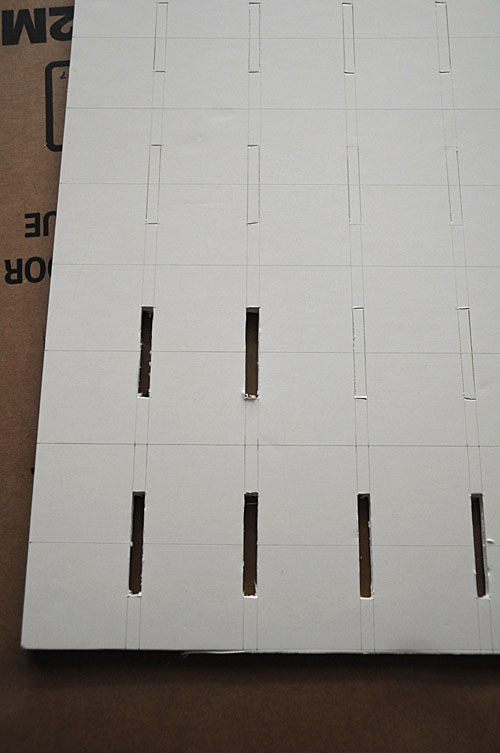
The first step was measuring and drawing out the cutting lines on the board in pencil. After my previous adventures in RGB LED Testing, I’d settled on an inside dimension of 2×2″ for each cell. Since the matrix is composed of 8×8 cells, I needed to cut 14 identical grid pieces. I tried to take a photo of the entire sheet after drawing in all the guide lines, but the lines didn’t show up clearly. Below is a close-up instead:

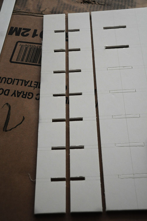
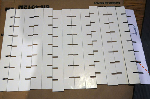
I found that it’s easiest to lay out the cuts so that the grooves on each adjacent pair of grid pieces are facing each other. This way, you can cut 2 slots at once. I first cut the slots, and then I cut out the grids:

Note that you need to use extremely sharp blades when cutting foam-core poster board. Once your blade begins to dull, it won’t cut through the foam smoothly, and instead, it makes it turn into nasty little chunks as the blade drags through. If your blade starts to dull, change to a new one. Also, make sure to avoid putting excessive pressure on the board with your elbows, knees, etc … once the foam compresses, it won’t bounce back. I spent about 5 hours total cutting out the 14 pieces below:

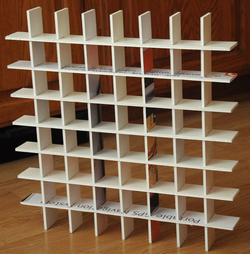
It was a tedious and boring task. Lucky I had a TV set in the room. When it was done, my arms, fingers, and back were all so sore, I had to pop 400mg of ibuprofen! Below are the fruits of my labor:

I bought a can of white gloss spray paint to paint over all of the printed bits, so unlike the photo above, the final product looks entirely white. In retrospect, I’m not sure it was worth using recycled board, because of the labor and cost of the paint. I’m not 100% sure that it was really necessary to paint it white – maybe the dark bits wouldn’t cause reduced brightness – but I didn’t want to take a risk … it would be hard to paint after wiring up the LED’s.

The next step is wiring up the 64 RGB LED’s … 4-wires each means a total of … 256 wires – 512 connections! Another long and grueling task!

Related articles:


Colorduino Library for Arduino

I wrote a Colorduino library for Arduino.  It handles initialization and double-buffered drawing on ITead Studio’s Colorduino.  It is also compatible with Itead’s Arduino RGB Matrix driver shield. Included with the library is a sample sketch to show how to use it, ColorduinoPlasma, which draws a pretty plasma on an 8×8 RGB matrix.

To install the library, download the zip file (see below), and copy libraries/Colorduino to your arduino sketchbook/libraries/Colorduino. If you are already running the Arduino IDE, you must restart it before you can use the library. You can then run load ColorduinoPlasma.pde demo.

To include the Colorduino library in your own sketch, just

#include <Colorduino.h>

Then your setup() function needs to just call two functions for initialization:

void setup()
{
Colorduino.Init();
// compensate for relative intensity differences in R/G/B brightness
// array of 6-bit base values for RGB (0~63)
// whiteBalVal[0]=red
// whiteBalVal[1]=green
// whiteBalVal[2]=blue
unsigned char whiteBalVal[3] = {36,63,63}; // for LEDSEE 6x6cm round matrix
Colorduino.SetWhiteBal(whiteBalVal);
}

Colorduino.SetWhiteBal() is used to adjust the white balance. You can put

ColorFill(255,255,255);

in your sketch to test the white balance by drawing a white screen.  Then adjust whiteBalVal until your screen approximates white.

The origin of the screen, (0,0) is at the bottom left corner. The off screen buffer can be accessed either pixel by pixel:

Colorduino.SetPixel(x,y,r,g,b);

or by direct manipulation.  The screen buffer is arranged by row. For instance to set all of the pixels in the second row to the same color:

PixelRGB *p = GetPixel(0,1);
for (int x=0;x < ColorduinoScreenWidth;x++) {
p->r = red;
p->g = green;
p->b = blue;
p++;
}

After you finish updating your screen, make it live by swapping it with the currently display buffer:

Colorduino.FlipPage();

The latest version of the Colorduino library can always be downloaded from github: https://github.com/lincomatic/Colorduino/archive/master.zip

ITead Studio Colorduino – A Preview

ITead Studio kindly sent me a Colorduino for beta testing. The Colorduino was inspired by SeeedStudio’s Rainbowduino LED Driver Platform. Its form factor is very similar to that of the Rainbowduino, and the layout of the connectors was intentionally designed to mimic the latter. Both boards are based on the ATmega368 MCU, and are Arduino compatible. The principal difference between the platforms is that while the Rainbowduino is based on 3 MBI5168 constant current sink drivers and a M54564 darlington source driver, the Colorduino pairs the M54564 with a single DM163 constant current driver. By using the DM163, the Colorduino gains three 8+6-bit channels of hardware PWM control of the LED’s freeing up the MCU from having to implement it in software. This gives the ATmega more CPU bandwidth for performing other tasks. In contrast, the Rainbowduino implements three 4-bit channels of software PWM. One important limitation, however, is that the DM163 only has 24 channels… this is just enough to buffer one line of 8 RGB LED’s (8×3 = 24), rather than an entire 8×8 RGB matrix. So while the MCU is freed of the software PWM task, it still has to constantly scan line by line to refresh the screen. However, the row scanning takes up considerably less CPU bandwidth than having to also handle software PWM, and ups the bit resolution of each color channel to 8+6 bits.

The extra 6 bits of data in each color channel allows software control of the relative PWM brightness, so that the user may not have to resort to using external resistors to adjust relative channel current (which is also supported by the DM163, but the Colorduino, unlike the Rainbowduino, does not have onboard potentiometers for adjusting individual RGB current).   The Colorduino is quite compact (the same size as the Rainbowduino), being slightly smaller than the 60x60mm common anode RGB LED for which it is designed as a direct plug-in.

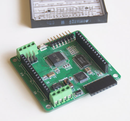
The Colorduino is pictured below:

Behind the Colorduino is my LEDSEE 60x60mm RGB matrix.

Below is a top view:

Keep in mind that this is a beta board, and ITead is still tweaking it.  One problem I found is that the ICSP header doesn’t have enough clearance for me to plug in my USBtinyISP.  The sliding switch is for selecting betwen onboard regulator (for use with 7-12V power supplies) or a regulated 5V input.  As you can see, the board is a bit rough looking, with crooked parts and flux residue.  ITead Studio has assured me that the ICSP header will be moved to a better location, and that the production boards will be cleaner.  Also, although the beta boards have an ATmega168, the production boards will use the ATmega368.  Note the 8-pin headers for easy daisy chaining.  When multiple boards are snapped together, a host can address each one individually via I2C.  The power is also easily interconnected between the boards via the dual 4-pin green screw terminals.  Bottom view below, snapped into the 8×8 RGB matrix:

From the photo above, you can see how compactness of the Colorduino.   It’s slightly smaller than the RGB matrix.  NOTE: The bypass cap yellow added between VDD and GND will be moved to the PCB before production.  One downside of the Colorduino (which is shared by the Rainbowduino), is the dearth of I/O pins left over for the user.  TX/RX/SCL/SDA are all you have to play with, and some or all of them may needed for communication.  If you need more I/O, a likely scenario will be to connect the Colorduino to an Arduino via I2C.  Kind of a shame, given that the hardware PWM frees up considerable CPU bandwidth for other functions.

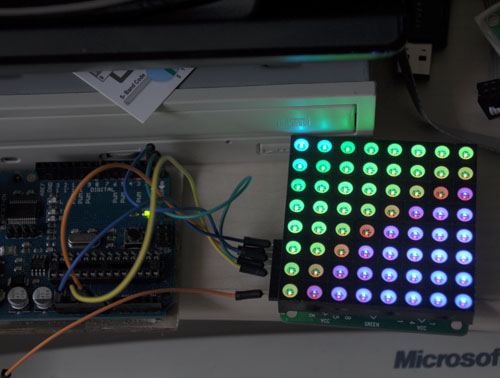
Below is the Colorduino running a plasma demo.  Notice my Arduino Duemilanove attached on the left, supplying power.  Since I can’t use ICSP, I’m using the Duemilanove, which you can see on the left, as a serial programmer.  I would like to get my USBtinyISP connected, so I regain some of the ATmega168’s small memory space by getting rid of the bootloader.

Finally, below is a rather horrible video of it running ITead’s demo code, followed by my plasma demo.  There is absolutely no flicker when viewed with the naked eye, what you see in the video is just an artifact.


The photos and video don’t do it justice.  The Colorduino supplies considerable drive current, making the matrix blindingly bright.  The LEDSEE 8×8 matrix is gorgeous.  I wish I could capture it properly in my photos.  I chose it because it was cheaper than the alternatives I found, while having the brightest output.  However, it took 2 weeks for LEDSEE to ship it out, and in total, it took over a month for me to receive it.  I sent them several inquiries about my order, which they completely ignored.   In light of their bad (nonexistent) customer service, I doubt I will deal with LEDSEE again.  ITead, on the other hand, has been quite responsive in their communications.

Currently, the Colorduino documentation is rather sparse.  ITead has a blog entry where you can download the schematic, DM163 spec, and their sample Arduino sketch.  ITead anticipates that the revisions will be completed and it will be put into their iStore sometime in April.  They are targeting a price of about $27, slightly higher than the Rainbowduino.  ITead Studio also makes an
Arduino RGB LED Matrix driver shield, which is already available for $14.80. When this shield is plugged into an Arduino Uno/Duemilanove, the combination is equivalent to a Colorduino, and uses exactly the same code.

Upon initial testing, the Colorduino appears to be a worthy challenger to the more established Rainbowduino, which has already spawned a dedicated ecosystem of  hackers, as well as a wiki full of detailed information. While the Colorduino has a lot of catching up to do, it seems quite capable, I look forward to running it through its paces in the coming weeks, when I use it to implement a large scale 8×8 RGB matrix.

You can download my plasma sketch, along with my interface library here: Colorduino Library for Arduino

RGB LED Testing

I bought 100 diffused 5mm RGB LED’s on eBay for my upcoming project, an 8×8 RGB matrix. I was extremely impressed by the fast (free) shipping – 7 days, all the way from China! Much to my chagrin, when I started testing them, I found that the vendor had sent me common cathode, rather than the common anode LED’s that I had been expecting. This is a big setback for me, because I was going to use them with the Colorduino that ITead Studio is graciously sending me for beta testing. The Colorduino expects common anode LED’s, so now I have a pile of 100 useless LED’s. Nevertheless, I decided to test them out to find out their brightness, color mixing, and diffusion characteristics.

Andy Rapp has posted a handy setup for testing RGB LED’s on his blog. He wrote a Java program and Arduino sketch, which allows you to interactively control an RGB LED with a host PC. I downloaded his code, and had it running very quickly.

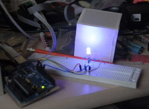
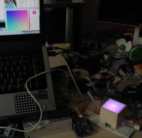
I also built a little 2x2x2 foam box, and put a piece of Grafix .005″ thick matte drafting film on top of it. The LED works fairly well. I’m satisfied with how well the combination diffuses the light.

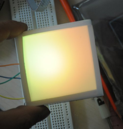
Andy’s Java app puts up a color picker on the host computer screen, which lets you interactively test out different colors in realtime. You can see the color picker in the bottom right corner of my computer screen. The brightness of a single LED is better than I was expecting, but the color mixing is not. It’s hard to see in the photos, but the red/green/blue components don’t mix that well, and the individual colors are brighter in certain areas.   In the photo above, notice how one side of the box is more purple, and the other side is more magenta.  This makes it impossible to get a decent approximation of white, even when you compensate for the fact that the 3 colors differ quite a bit in brightness when the same current is passed through them.  Below are some more shots.  In the yellow shot, I’m raising the box up so that the LED is lined up with the bottom of the box.  This makes the light noticeably smoother looking.   Note how the light is not centered in the box, even though I have the LED pointing perfectly vertical.  I may have to make minor adjustments when I build the real matrix.

It looks bright enough that I may be able to get away with just using 1 LED per cell.  I’ll have to see when I get the correct common anode LED’s and the Colorduino to play with.

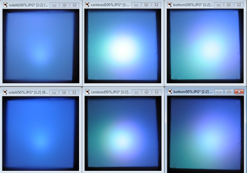
UPDATE: I did some more testing.  In the photo below, the top row is @ 100% brightness, and the bottom row is @ 50% brightness.  In the left column (“sidelit”), the LED is centered in the box, but pointing to one of the walls (so the view of the LED through the hole is the side of the LED).  In the center column (“centered”), the LED is pointing straight at the  and is physically centered in the box.  In the right column (bottom), the LED is pointing straight at the drafting film, but aligned w/ the bottom of the box.  As you can see, the “sidelit” setup has the best color mixing and is the most even in brightness.  The “centered” setup is brightest, but has the biggest hot spot, and the colors don’t mix as well.  The “bottom” setup is a bit more even in brightness, but still suffers from uneven color mixing.  I’m still undecided about which way to go.  What I like about the “sidelit” setup is that it enables the option of making a free-standing matrix that lights up two sides instead of just one.  I guess I’ll have to put off the decision making until I get the Colorduino and the common anode LED’s.  I contacted the eBay vendor this afternoon, and he says he’ll rush out the common anode LED’s tomorrow.  Hopefully, they will arrive in a week.

Comparison of LED placements - click to see full size

Build Your Own Daft Punk Table (5×5 LED Display)

Welcome my blog. This is my first post.

This is a 5×5 LED matrix display I built, using an ATmega368 microcontroller (arduino) and 25 warm white LED’s.  It was inspired by the Daft Punk coffee table, which is no longer sold.
I posted my first Instructable last Sunday.  It got selected by the editors to be Featured, which won me a free 3-month Pro membership.  I entered it into the Sparkfun Microcontroller Contest.  Today is the last day of voting.

http://www.instructables.com/id/Yet-Another-Daft-Punk-Coffee-TableDisplay/

I will be revising it and adding features, such as live music synchronization. I will post the developments on this blog as they happen, with detailed instructions.