ITead Studio kindly sent me a Colorduino for beta testing. The Colorduino was inspired by SeeedStudio’s Rainbowduino LED Driver Platform. Its form factor is very similar to that of the Rainbowduino, and the layout of the connectors was intentionally designed to mimic the latter. Both boards are based on the ATmega368 MCU, and are Arduino compatible. The principal difference between the platforms is that while the Rainbowduino is based on 3 MBI5168 constant current sink drivers and a M54564 darlington source driver, the Colorduino pairs the M54564 with a single DM163 constant current driver. By using the DM163, the Colorduino gains three 8+6-bit channels of hardware PWM control of the LED’s freeing up the MCU from having to implement it in software. This gives the ATmega more CPU bandwidth for performing other tasks. In contrast, the Rainbowduino implements three 4-bit channels of software PWM. One important limitation, however, is that the DM163 only has 24 channels… this is just enough to buffer one line of 8 RGB LED’s (8×3 = 24), rather than an entire 8×8 RGB matrix. So while the MCU is freed of the software PWM task, it still has to constantly scan line by line to refresh the screen. However, the row scanning takes up considerably less CPU bandwidth than having to also handle software PWM, and ups the bit resolution of each color channel to 8+6 bits.
The extra 6 bits of data in each color channel allows software control of the relative PWM brightness, so that the user may not have to resort to using external resistors to adjust relative channel current (which is also supported by the DM163, but the Colorduino, unlike the Rainbowduino, does not have onboard potentiometers for adjusting individual RGB current). The Colorduino is quite compact (the same size as the Rainbowduino), being slightly smaller than the 60x60mm common anode RGB LED for which it is designed as a direct plug-in.
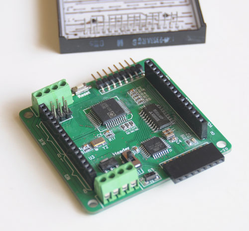
The Colorduino is pictured below:
Behind the Colorduino is my LEDSEE 60x60mm RGB matrix.
Below is a top view:
Keep in mind that this is a beta board, and ITead is still tweaking it. One problem I found is that the ICSP header doesn’t have enough clearance for me to plug in my USBtinyISP. The sliding switch is for selecting betwen onboard regulator (for use with 7-12V power supplies) or a regulated 5V input. As you can see, the board is a bit rough looking, with crooked parts and flux residue. ITead Studio has assured me that the ICSP header will be moved to a better location, and that the production boards will be cleaner. Also, although the beta boards have an ATmega168, the production boards will use the ATmega368. Note the 8-pin headers for easy daisy chaining. When multiple boards are snapped together, a host can address each one individually via I2C. The power is also easily interconnected between the boards via the dual 4-pin green screw terminals. Bottom view below, snapped into the 8×8 RGB matrix:
From the photo above, you can see how compactness of the Colorduino. It’s slightly smaller than the RGB matrix. NOTE: The bypass cap yellow added between VDD and GND will be moved to the PCB before production. One downside of the Colorduino (which is shared by the Rainbowduino), is the dearth of I/O pins left over for the user. TX/RX/SCL/SDA are all you have to play with, and some or all of them may needed for communication. If you need more I/O, a likely scenario will be to connect the Colorduino to an Arduino via I2C. Kind of a shame, given that the hardware PWM frees up considerable CPU bandwidth for other functions.
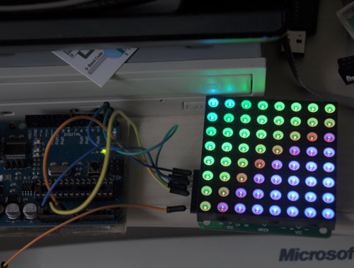
Below is the Colorduino running a plasma demo. Notice my Arduino Duemilanove attached on the left, supplying power. Since I can’t use ICSP, I’m using the Duemilanove, which you can see on the left, as a serial programmer. I would like to get my USBtinyISP connected, so I regain some of the ATmega168’s small memory space by getting rid of the bootloader.
Finally, below is a rather horrible video of it running ITead’s demo code, followed by my plasma demo. There is absolutely no flicker when viewed with the naked eye, what you see in the video is just an artifact.
The photos and video don’t do it justice. The Colorduino supplies considerable drive current, making the matrix blindingly bright. The LEDSEE 8×8 matrix is gorgeous. I wish I could capture it properly in my photos. I chose it because it was cheaper than the alternatives I found, while having the brightest output. However, it took 2 weeks for LEDSEE to ship it out, and in total, it took over a month for me to receive it. I sent them several inquiries about my order, which they completely ignored. In light of their bad (nonexistent) customer service, I doubt I will deal with LEDSEE again. ITead, on the other hand, has been quite responsive in their communications.
Currently, the Colorduino documentation is rather sparse. ITead has a blog entry where you can download the schematic, DM163 spec, and their sample Arduino sketch. ITead anticipates that the revisions will be completed and it will be put into their iStore sometime in April. They are targeting a price of about $27, slightly higher than the Rainbowduino. ITead Studio also makes an
Arduino RGB LED Matrix driver shield, which is already available for $14.80. When this shield is plugged into an Arduino Uno/Duemilanove, the combination is equivalent to a Colorduino, and uses exactly the same code.
Upon initial testing, the Colorduino appears to be a worthy challenger to the more established Rainbowduino, which has already spawned a dedicated ecosystem of hackers, as well as a wiki full of detailed information. While the Colorduino has a lot of catching up to do, it seems quite capable, I look forward to running it through its paces in the coming weeks, when I use it to implement a large scale 8×8 RGB matrix.
You can download my plasma sketch, along with my interface library here: Colorduino Library for Arduino


Because there is no cooling plate on the DM163, so we don’t suggest use more than 7V power supply for it via the terminal side. For the header side, had better use the 5V power supply. We try use the 12V to power it, and the DM163 damaged because of overheating. In finial version, we will add a small cooling plate on the chip to protect it.
I just want to make sure I understand correctly.. so the beta version should be powered by <= 7V on the Vin terminal, but the production version will be OK with 12V?
Hello, I too have a beta board. Just a couple of questions:
Power with 5V ?
Pin 1 of the LED matrix connects to which pin in the board
Thanks. Great review!
5V if through the black header (sliding switch up), or 7V on the green terminal (sliding switch down). You should really check the pinouts on your matrix to make sure it’s compatible… mine uses pin 1 on the top (red/blue header).
Thanks for the info. The matrix came from iTeadStudio. I’ll assume the same as yours?
You are right about the lack of pins. After uploading the program, how do you add a knob? to for example change the color…
No, I’m using LEDSEE’s matrix. I think yours is pin-compatible, but you should check yourself. I’m using pin A4 (SDA) for input
Hello! I love your work! I am very keen to get started on a DP Table project and wondered if you have a full guide as Mr Galletta’s is a little brief!?
I’m determined to do it!
Kind regards
Hi, yes, I built a table top version of the DP display. If you’re going to build a real coffee table you will have to add some transistors to drive extra LED’s… it will be a bit dim if you want to scale it up.
See my instructable for the gory details: http://www.instructables.com/id/Yet-Another-Daft-Punk-Coffee-TableDisplay/
I get the impression, but it’s not clear– that it uses a serial port to control the display? If so it won’t work for me, as my serial ports are tied up doing other things. I want to be sure though, as having some kind of display output capability would be useful…
I’m using the serial port, but they can be controlled via I2C as well. If you want I2C, you can ask if Nick if he will share some code with you.
So this is probably a dumb question, but … I have some ultra-bright LEDs spec’ed at 100 mA nominal current, 120 mA max. Can I tie two of the color channels from the Colorduino together (say R and B), each of which can sink about 58 mA, and connect them to the LED anode to give me 116 mA in total current through the LED? I’ll be putting together an 8×8 matrix of these, but will only have one LED at any one time, with a very short duty cycle (about 5 seconds on, then minutes off).
I don’t think that’s a good idea. You should use transistors to drive the LED’s.
Discrete: http://forum.allaboutcircuits.com/showthread.php?t=70843
IC: http://arduino.cc/forum/index.php?topic=90619.0
Many thanks; points me in a better direction.
As far as the arduino code is concerned, it seems that boards with an LED array, for example 64×16 (bicolor) with the hub08 driver, are easier to find; what do you think?
I like it and a colorful (neat) scrolling text but I can not find it!
Hello Colorduino gurus…
Does anyone know how to adjust the brightness? setting RGB to 255 is ok but the display is really only coasting at about half brightness. How do I know? Coz I can do a random walk through memory and trash the system causing random pixels to really pump and it looks real bright!
Any help would be much appreciated…
As an aside, has anyone got a sample sketch to do a shooting star over the 64 leds using this matrix? would be a great help to me.
cheers
Karl
I think the brightness level is a limitation of the hardware, unfortunately. It multiplexes the LEDs, so they aren’t on continuously
Thanks for the info. I think the panel is fairly useless then alas . Far too dim to drive a fibre optic display :(.
Regards
Karl
Can you please show which pins you conected with Arduino. I cant click on the video. I want to know what you conected with arduino and the Matrix LED
there’s a schematic here: https://www.instructables.com/Lampduino-an-8×8-RGB-Floor-Lamp/