ITEAD Studio IBOX – Part 1: First Look

ITEAD Studio recently contacted me to let me know that they’re going to display my Lampduino project at the Shenzhen Makerfaire. I thought that was a pretty cool idea, and am honored to hear that. They also asked if I wanted to test out their IBOX mini multifunction single board computer, which is currently in its final days of its campaign on Indiegogo, having already raised over 4.5x its funding goal. The IBOX is designed with hackers in mind, and is driven by an Allwinner A20 ARM Cortex-A7 processor. Here are the salient hardware specs:

  • CPU Dual-core ARM Cortex-A7
  • GPU Mali 400 MP
  • DDR3 RAM 1GByte
  • NAND FLASH 4GByte
  • 4x USB
  • 1x HDMI
  • 1x optical S/PDIF
  • 1x 100BT Ethernet
  • 1x 7-24V DC power jack

ITEAD touts the IBOX as a very open hackers platform, capable of running a plethora of OS’s.  Currently, the following distros are available for booting from its onboard NAND flash:

  • Android TV A20 (from ITEAD)
  • Android 4.2 (from Cubietech)
  • Lubuntu (from Cubietech)

The following distros must be booted from the microSD:

  • Android SD bootable image (from LinkSprite)
  • Debian 7.0 (from ITEAD)
  • Cubian (from Liu)
  • Arch Linux (from archlinuxarm.org)

The IBOX comes in an anodized aluminum case that has a glossy plexiglas top:

top

Being a pre-production sample, I’ll excuse the fact that the top had a lot of superficial scratches on it, but I wonder if a matte surface would be better, since it scratches so easily. The left side of the unit contains a plethora of connectivity:

left

The small rectangle on the left labeled Uboot is a switch for entering the U-Boot bootloader. The right side contains a micro SD slot:

right

Behind the rectangular window is a 2-color status LED and an IR receiver for talking to remote controls. The back panel contains a 32-pin expansion interface connector:

back

The expansion connector is what really separates the IBOX from the typical ARM mini PC. It opens up the platform for hardware hackers, containing pins for UART, TWI, SPI, SATA, etc.  You can find the full pinouts on the Indiegogo page. The bottom of the IBOX is held on with 4 Philips screws:

bottom

A set of rubber feet would be a nice addition.  Removing the metal bottom cover reveals the bottom of the baseboard:

botpcb

The baseboard is a very tight fit into the case.  In order to remove it, you must first pry the it away far enough to clear the various ports from their cutouts in left side of the case, and then pry upwards from the front.  The baseboard is a modular backplane which contains all of the I/O connectors, as well as the socketed core board:

pcbtop

The core board is essentially the “brain” of the IBOX, containing the A20 processor, RAM, etc. Since the core board is socketed, it can be swapped out as newer, more powerful ones become available (e.g. A31, etc).  Here is a close-up of the A20 core board:

coreboard

Note that there are two pushbuttons, SW1 and SW2. I’m not sure of their purpose, but they are not accessible when the IBOX is assembled. The plexiglas top was attached to my IBOX with some rather messy clear silicone caulk:

inside

Again, I’ll excuse the mess because it’s a pre-production sample. I hope that the production units will have cleaner assembly.

So far, the IBOX looks like an interesting platform for building an energy efficient media center, file server, http server, etc. I’m looking forward to powering it up and putting it through its paces. Perhaps I will use it to replace my Raspberry PI that’s currently running XBMC. In my next article, I will boot up the IBOX, and test it out.

Resources:

Indiegogo campaign – the most information can currently be found on this page.
ITEAD blog – contains various informative posts on the IBOX
A20 core board schematic
IBOX baseboard schematic
IBOX baseboard design files
Case dimensions
distro downloads

Noritake 24×6 Character VFD Module

I’ve always thought VFDs were pretty cool. They used to be the rage in high end consumer electronics. Back in the mid 70’s, I built a VFD alarm clock. Recently, I got my hands on a modern VFD module to play with. The Noritake-itron SCK-Y100-24063-N14 is a very flexible 24×6 character VFD module in the same form factor of a 20×4 character LCD module. It is a member of Noritake’s CU-Y series VFDs.

vfdardu

Overview

  • 5V supply voltage
  • serial (asynchronous and synchronous) and 8-bit parallel communication
  • CMOS signal and RS-232 (+-15V) voltage compatible
  • jumper-selectable baud rate: 9600, 19200, 38400(default), 115200.
  • extensive built-in character sets: USA, European, Japanese (Katakana only), Multilingual – various fonts and symbols, Canadian and French, Nordic, WPC1252 – european fonts and symbols, Cyrillic, Latin, Portuguese, PC858 – european fonts and symbols
  • adjustable brightness
  • locally selectable brightness for highlighting (useful for implementing menus)
  • double width, and double width & height characters

The video below compares the Noritake 26×6 VFD to a 20×4 LCD. The characters are noticeably smaller on the VFD due to the higher density, but still quite readable.

This page shows some of the versatility of the Noritake VFD: Versatile Character Display CU-Y Series

The VFD comes pre-configured to operate in async serial mode at 38400 baud. It isn’t necessary to use a UART to talk to the VFD; any GPIO pins will suffice. A minimum of 2 pins are needed, for SIN (input) and SBUSY (output). A third GPIO pin can be connected to RESET (input). I hooked mine up to an Arduino UNO as follows:

D2 -> SIN
D3 -> SBUSY
D4 -> RESET

Here’s what it looks like from the front, running Noritake’s Arduino menu demo:

vfdfront

The lower contrast on the left side of the photo is due to my camera’s reflection – the glass is very reflective. Note the highlighting via localized variations in brightness. Here’s what it looks like with a blue filter on top (again, apologies for the reflections – it actually looks a lot better than this photo):

vfdblue

Though my photos are crap, the display is quite easy to read indoors. I wouldn’t recommend it for outdoor use, however, or anywhere that you expect direct sunlight.

Back view:

vfdback

The 10-pin  jumper block on the top center is used for configuration, and the 14-pin jumper block on the bottom right is used only for parallel mode.

The writing speed of this VFD is very fast. Running in async serial mode on an Arduino UNO at 38400 baud, I was able to output 120 characters in a mere 38ms, which is about 3x faster than LiquidTWI2 can muster, even after the I2C bus is tweaked (and over 100x faster than LiquidTWI2 w/o I2C bus frequency tweaking). Unfortunately, Noritake’s Arduino library doesn’t compile on a Teensy 3.x, because it contains AVR assembly code in a timing function, and calls _delay_us(), which isn’t implemented on the Teensy 3.x. On the other hand, it should not be hard to replace these two functions. To use the Noritake VFD with Arduino, first download the Arduino code library. From the Arduino IDE’s pull-down menu, use Sketch->Import Library…->Add Library... to import Arduino_Noritake_VFD_CUY.zip. Include the following headers into your sketch:

[code language=”c”]
#include <CUY_Interface.h>
#include <CUY_Serial_Async.h>
#include <Noritake_VFD_CUY.h>
[/code]

Two classes need to be instantiated:

[code language=”c”]
CUY_Serial_Async interface(38400,2, 3, 4); // SIN,BUSY,RESET
Noritake_VFD_CUY vfd;
[/code]

Here is what initialization looks like:

[code language=”c”]
void setup() {
delay(500); // wait for device to power up
vfd.begin(24, 4); // 24×4 character module
vfd.interface(interface); // select which interface to use
vfd.isModelClass(Y100);
vfd.CUY_init(); // initialize the module
}
[/code]

Note that Noritake chose to implement only partial compatibility with the LiquidCrystal library.  So while vfd.print(s) is supported, vfd.setCursor(x,y) is not; one has to instead call vfd.CUY_setCursor(x,y). The Noritake_VFD_CUY class methods are declared in Noritake_VFD_CUY.h. Noritake includes a few sample sketches, which you can access from Arduino’s menu via File->Examples->CUY.

Noritake also provides a handy host program, which lets you configure and test the display without a microcontroller.

cue-y_373x350

To use the program, connect the VFD to a PC running Microsoft Windows via a Serial->USB adapter, such as an FTDI cable. Using the Serial->USB adapter opens up the possibility of using the VFD  as a USB auxilliary display for a PC.

The Noritake SCK-Y100-24063-N14 is a very cool device, and I’m looking forward to building a project with it.

Resource Links

SCK-Y100-24063-N14 Overview 
CU-Y: Y-Series Evaluation Software
Code Library
Arduino Library with examples
Sample C++ code and configuration/hookup
How to use custom fonts
How to use the built-in font tables
How to use the font magnification command
How to create a menu using the highlight effect

Logging Rainforest RAVEn/EMU-2 Data to ThingSpeak (node.js on Raspberry Pi)

Last year, I bought a Rainforest EMU-2 energy monitor.  It wirelessly talks via zigbee to the smart energy meter that SCE installed at my house a couple of years ago. Unfortunately, its logging capabilities are rather primitive. All it does is give you a crude bar graph of the current and previous day’s usage. SCE actually has fairly detailed logs on their website, which you can access without buying your own energy monitor, but it’s cumbersome to log into their website and navigate down to the pages. Fortunately, a nice feature of the EMU-2 is that it has a USB port which behaves exactly like the Rainforest RAVEn, so you can read out the data into a computer and log it. I decided to hook up the EMU-2 to a Raspberry Pi, and log the data to ThingSpeak with node.js.

Step 1: Install node.js on Raspberry Pi

Unfortunately, the version of node.js that installs via apt-get on the Adafruit Occidentalis distro that I run on my Raspberry Pi is rather old (v 0.6.19), and won’t work with our code. I had to manually install from the nodejs repository:

wget http://nodejs.org/dist/v0.10.22/node-v0.10.22-linux-arm-pi.tar.gz
tar xzf node-v0.10.22-linux-arm-pi.tar.gz
cp -R node-v0.10.22-linux-arm-pi/bin /usr/local
cp -R node-v0.10.22-linux-arm-pi/lib /usr/local
cp -R node-v0.10.22-linux-arm-pi/share /usr/local
echo export NODE_PATH=/usr/local/lib/node_modules:/usr/local/lib/node_modules/npm/node_modules >> ~/.bashrc
source ~/.bashrc

I’m using node.js v0.10.22 because it works, and that’s the version that I’m using on my Debian development machine. I tried to install the latest, v0.11.11, but ran into all sorts of errors.

Step 2: Install node.js libraries

My RAVEn logging script depends on some libraries, serialportthingspeakclient, and xml2js, which we can install via npm:

npm install -g serialport thingspeakclient xml2js

Step 3: node.js code

The RAVEn XML API is fairly simple. To make things even simpler, I found that stormboy had already written a node.js library to decode it and github: stormboy/node-raven. node-raven reads data from RAVEn and uploads it to an MQTT server, so I had to modify the code to upload to ThingSpeak. Below is my script:

[code language=”java”]
/**
* Reads energy data from a smart meter via a RAVEn RFA-Z106 dongle (http://www.rainforestautomation.com/raven) and uploads to ThingSpeak.
hacked from stormboy’s node-raven https://github.com/stormboy/node-raven
by Sam C. Lin
*/

var serialport = require("serialport"),
ThingSpeakClient = require(‘thingspeakclient’),
xml2js = require(‘xml2js’);

process.on(‘uncaughtException’, function(err) {
// handle the error safely
console.log(err);
});

var TRACE = true;

// RAVEn’s serial port
var ravenSerialPath = ‘/dev/ttyUSB0’;

// thingspeak parameters
var channelId = YOUR-THINGSPEAK-CHANNELID;
var apiKey = ‘YOUR-THINGSPEAK-WRITE-API-KEY’;

var tsclient = new ThingSpeakClient();
tsclient.attachChannel(channelId, { writeKey:apiKey});

// date offset for RAVEn which presents timestamp as seconds since 2000-01-01
var dateOffset = Date.UTC(2000, 0, 1);

var dailyNet = 0;
var dailyNetSentDate = 0;

var Raven = function(serialPath) {
var self = this;

// configure the serial port that the RAVEn USB dongle is on.
this.serialPort = new serialport.SerialPort(serialPath, {
baudrate: 115200,
databits: 8,
stopbits: 1,
parity: ‘none’,
parser: serialport.parsers.readline("\r\n")
});

this.serialPort.on("open", function() {
openHandler(self);
});
};

/**
* Get the connection status between the USB device and the power meter
*/
Raven.prototype.getConnectionStatus = function() {
var queryCommand = "<Command><Name>get_connection_status</Name></Command>\r\n";
this.serialPort.write(queryCommand);
};

/**
* Get information about the device
*/
Raven.prototype.getDeviceInfo = function() {
var queryCommand = "<Command><Name>get_device_info</Name></Command>\r\n";
this.serialPort.write(queryCommand);
};

/**
* Query the amount of energy used or fed-in.
*/
Raven.prototype.getSumEnergy = function() {
var queryCommand = "<Command><Name>get_current_summation_delivered</Name></Command>\r\n";
this.serialPort.write(queryCommand);
};

/**
* Get the power currently being used (or fed-in)
*/
Raven.prototype.getSumPower = function() {
var queryCommand = "<Command><Name>get_instantaneous_demand</Name></Command>\r\n";
this.serialPort.write(queryCommand);
};

Raven.prototype.getMessage = function() {
var queryCommand = "<Command><Name>get_message</Name></Command>\r\n";
this.serialPort.write(queryCommand);
};

Raven.prototype.getTime = function() {
var queryCommand = "<Command><Name>get_time</Name></Command>\r\n";
this.serialPort.write(queryCommand);
};

Raven.prototype.getCurrentPrice = function() {
var queryCommand = "<Command><Name>get_current_price</Name></Command>\r\n";
this.serialPort.write(queryCommand);
};

Raven.prototype.close = function() {
this.serialPort.close();
};

// handle serial port open
function openHandler (self) {
var parser = new xml2js.Parser();
var buffer = ""; // read buffer.

if (TRACE) {
console.log(‘serial device open’);
}

// add serial port data handler
self.serialPort.on(‘data’, function(data) {
buffer += data.toString() + "\r\n"; // append to the read buffer
if ( data.toString().indexOf(‘</’) == 0 ) { // check if last part of XML element.

// try to parse buffer
parser.parseString(buffer, function (err, result) {
if (err) {
console.log("err: " + err);
console.log(‘data received: ‘ + buffer);
}
else if (result.InstantaneousDemand) {
var timestamp = parseInt( result.InstantaneousDemand.TimeStamp );
timestamp = new Date(dateOffset+timestamp*1000);
var demand = parseInt( result.InstantaneousDemand.Demand, 16 );
demand = demand < 0x80000000 ? demand : – ~demand – 1;
if (TRACE) {
console.log("demand: " + timestamp.toLocaleString() + " : " + demand);
}
var tsData = new Object();
tsData = { field1: demand };
tsclient.updateChannel(channelId,tsData);
}
else if (result.CurrentSummationDelivered) {
var timestamp = parseInt( result.CurrentSummationDelivered.TimeStamp );
timestamp = new Date(dateOffset+timestamp*1000);
var used = parseInt( result.CurrentSummationDelivered.SummationDelivered, 16 );
var fedin = parseInt( result.CurrentSummationDelivered.SummationReceived, 16 );
var curDate = timestamp.getDate();
var net = used – fedin;

if (dailyNet == 0) {
dailyNet = net;
dailyNetSentDate = curDate;
}

if (TRACE) {
console.log("sum: " + timestamp.toLocaleString() + " : " + used + " – " + fedin);
}

var tsData = new Object();
tsData = { field2: net,field3: used,field4: fedin};

// only send daily net once a day
if (curDate !== dailyNetSentDate) {
tsData.field5 = net – dailyNet;
dailyNet = net;
dailyNetSentDate = curDate;
}

tsclient.updateChannel(channelId,tsData);

}
else if (result.ConnectionStatus) {
if (TRACE) {
console.log("connection status: " + result.ConnectionStatus.Status);
}
}
else {
if (TRACE) {
console.dir(result); // display data read in
}
}
});
buffer = ""; // reset the read buffer
}
});
}

var raven = Raven(ravenSerialPath);
[/code]

Before you can run the script, you must ravenSerialPath, channelId, and apiKey to match your own configuration. Node that the code contains several getters which I don’t use, because by default, my EMU-2 sends out the data via the USB serial port at regular intervals.

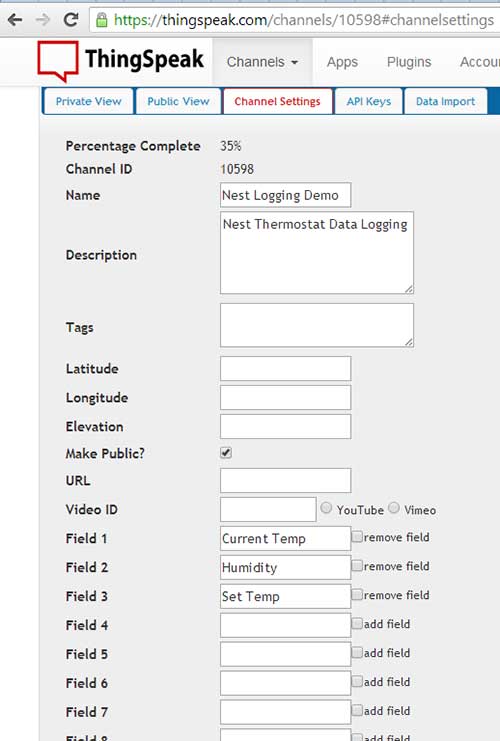
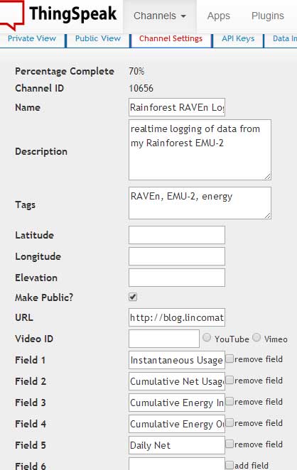
Step 4: ThingSpeak Channel Configuration

Next, you must create a new ThingSpeak channel with 5 fields:
tsraven

Step 5: Run our node.js script

node raven-log.js &

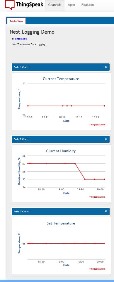
Below are the live data from my ThingSpeak channel: Rainforest RAVEn Logging Demo


I will be updating the code from time to time. You can always get the latest version from github: lincomatic/raven-thingspeak

Logging Nest Thermostat Data: Update 1

I have updated my Nest thermostat data logger. The changes are as follows:

  1. added fan status, heater status, and AC status.
  2. polling interval increased from 15 min to 1 min.
  3. data are pushed to ThingSpeak only if at least one field changes.

The new node.js code:

[code language=”java”]
"option strict";
var util = require(‘util’),
ThingSpeakClient = require(‘thingspeakclient’);
nest = require(‘unofficial-nest-api’); // get from npm

process.on(‘uncaughtException’, function(err) {
// handle the error safely
console.log(err);
});

// nest parameters
var username = ‘YOUR-NEST-LOGIN’;
var password = ‘YOUR NEST PASSWORD’;

// thingspeak parameters
var channelId = YOUR-THINGSPEAK-CHANNEL-ID;
var apiKey = ‘YOUR THINGSPEAK-WRITE-API-KEY’;

// update interval in ms
var updateInterval = 1000*60;

var tsclient = new ThingSpeakClient();
tsclient.attachChannel(channelId, { writeKey:apiKey});

var setTemp = 0;
var curTemp = 0;
var curHum = 0;
var curFanState = -1;
var curHeaterState = -1;
var curACState = -1;

function trimQuotes(s) {
if (!s || s.length === 0) {
return ”;
}
var c = s.charAt(0);
var start = (c === ‘\” || c === ‘"’) ? 1 : 0;
var end = s.length;
c = s.charAt(end – 1);
end -= (c === ‘\” || c === ‘"’) ? 1 : 0;
return s.substring(start, end);
}

function merge(o1, o2) {
o1 = o1 || {};
if (!o2) {
return o1;
}
for (var p in o2) {
o1[p] = o2[p];
}
return o1;
}

function fetchData(data) {
nest.login(username, password, function (err, data) {
if (err) {
console.log(err.message);
//process.exit(1);
return;
}

nest.fetchStatus(function (data) {
for (var deviceId in data.device) {
if (data.device.hasOwnProperty(deviceId)) {
var shared = data.shared[deviceId];
var date = new Date();
var time = date.getFullYear()+’/’+date.getMonth()+’/’+date.getDate()+’-‘+date.getHours()+’:’+date.getMinutes();
var cTemp = nest.ctof(shared.current_temperature);
var sTemp = nest.ctof(shared.target_temperature);
var cHum = data.device[deviceId].current_humidity;
var cFanState = (shared.hvac_fan_state == true) ? 1 : 0;
var cHeaterState = (shared.hvac_heater_state == true) ? 1 : 0;
var cACState = (shared.hvac_ac_state == true) ? 1 : 0;

console.log(util.format("%s %s [%s], cur temp: %d F cur humidity: %d %% set temp: %d fan: %s heat: %s AC: %s",
time,
shared.name, deviceId,
cTemp,
cHum,
sTemp,
cFanState ? ‘on’ : ‘off’,
cHeaterState ? ‘on’ : ‘off’,
cACState ? ‘on’ : ‘off’
));
if ((cTemp !== curTemp) || (cHum !== curHum) ||
(sTemp !== setTemp) || (cFanState !== curFanState) ||
(cHeaterState !== curHeaterState) ||
(cACState !== curACState)) {
var tsData = new Object();
tsData.field1 = cTemp;
tsData.field2 = cHum;
tsData.field3 = sTemp;
tsData.field4 = cFanState;
tsData.field5 = cHeaterState;
tsData.field6 = cACState;
console.log("sending to thingspeak");
tsclient.updateChannel(channelId,tsData);
}
curTemp = cTemp;
curHum = cHum;
setTemp = sTemp;
curFanState = cFanState;
curHeaterState = cHeaterState;
curACState = cACState;
}
}
});
});
}

fetchData();
setInterval(fetchData,updateInterval);
[/code]

The corresponding ThingSpeak Channel also needs to have 3 new fields added to it:

  1. Field 4: Fan State
  2. Field 5: Heater State
  3. Field 6: AC State

I am currently running the demo on a Raspberry Pi. As before, you can view my live channel on ThingSpeak: Nest Logging Demo

I will be updating the code from time to time.  You can always get the latest version from github: lincomatic/nest-thingspeak

Related Articles: Nest

Logging Nest Thermostat Data

I recently had a Nest Thermostat installed at my house for free by my gas company as part of a pilot program that they’re running. It’s a pretty cool device, though I wouldn’t spend $250 to buy one. I like the fact that it’s a lot easier to use than my previous smart thermostat, especially being able to program it from a computer or my smartphone.  One very interesting feature to me is that it tracks the relative humidity of my house. Unfortunately, the Nest app doesn’t let you keep a running log of your data, so I decided to hack together a solution today.

I used node.js to implement a data logger which queries some parameters from my Nest thermostat, and upload it to ThingSpeak at regular intervals. Specifically, my node.js script uploads my Nest’s current temperature, humidity, and the current set temperature to thingspeak every 15 minutes. Below is the node.js script:

[code language=”java”]
"option strict";
var util = require(‘util’),
ThingSpeakClient = require(‘thingspeakclient’);
nest = require(‘unofficial-nest-api’); // get from npm

// nest parameters
var username = ‘YOUR-NEST-USERNAME’;
var password = ‘YOUR-NEST-PASSWORD’;

// thingspeak parameters
var channelId = YOUR-THINGSPEAK-CHANNELID;
var apiKey = ‘YOUR-THINGSPEAK-WRITE-API-KEY’;

// update interval in ms
var updateInterval = 1000*60*15;

var tsclient = new ThingSpeakClient();
tsclient.attachChannel(channelId, { writeKey:apiKey});

function trimQuotes(s) {
if (!s || s.length === 0) {
return ”;
}
var c = s.charAt(0);
var start = (c === ‘\” || c === ‘"’) ? 1 : 0;
var end = s.length;
c = s.charAt(end – 1);
end -= (c === ‘\” || c === ‘"’) ? 1 : 0;
return s.substring(start, end);
}

function merge(o1, o2) {
o1 = o1 || {};
if (!o2) {
return o1;
}
for (var p in o2) {
o1[p] = o2[p];
}
return o1;
}

function fetchData(data) {
nest.login(username, password, function (err, data) {
if (err) {
console.log(err.message);
process.exit(1);
return;
}

nest.fetchStatus(function (data) {
for (var deviceId in data.device) {
if (data.device.hasOwnProperty(deviceId)) {
var shared = data.shared[deviceId];
var date = new Date();
var time = date.getFullYear()+’/’+date.getMonth()+’/’+date.getDate()+’-‘+date.getHours()+’:’+date.getMinutes();

console.log(util.format("%s %s [%s], Current temp: %d F Current Humidity: %d %% Target temp: %d",
time,
shared.name, deviceId,

nest.ctof(shared.current_temperature),
data.device[deviceId].current_humidity,

nest.ctof(shared.target_temperature)));

var fields = { field1: nest.ctof(shared.current_temperature),field2: data.device[deviceId].current_humidity, field3: nest.ctof(shared.target_temperature)};
tsclient.updateChannel(channelId,fields);
}
}
});
});
}

fetchData();
setInterval(fetchData,updateInterval);
[/code]

In order to run my node.js script, you need to first use npm to install unofficial-nest-api and thingspeakclient. My script is actually just a hacked up version of the example that comes with unofficial-nest-api.

Note that you must first update the initialization of username and password with your Nest.com login credentials.

Also, you need to enter your channel id and write api key from thingspeak.com. Below are my thingspeak channel settings:

channel

You can view my channel live on thingspeak here: Nest Logging Demo

channelview

TL-WR703N: Adding Storage Space – EXTROOT

Once you have your TL-WR703N running OpenWrt, you’ll find that it doesn’t have a lot of free space for adding your own files. Here is the output from df from after installing attitude-adjustment:

root@OpenWrt:/# df -h
Filesystem Size Used Available Use% Mounted on
rootfs 1.1M 352.0K 736.0K 32% /
/dev/root 2.0M 2.0M 0 100% /rom
tmpfs 14.3M 56.0K 14.2M 0% /tmp
tmpfs 512.0K 0 512.0K 0% /dev
/dev/mtdblock3 1.1M 352.0K 736.0K 32% /overlay
overlayfs:/overlay 1.1M 352.0K 736.0K 32% /

Note how rootfs has only 736KB free.  Luckily, there’s an easy way to put your rootfs onto external storage (extroot), which lets you easily expand your root file system onto a USB flash drive. In the instructions below, I will illustrate how to implement the pivot overlay flavor of extroot.

First, format your USB flash drive with an ext4 filesystem. I used an old 512MB Crucial USB drive. If you are using Windows, MiniTool Partition Wizard Home Edition can easily create an ext4 filesystem on your USB flash drive.

Before you can mount the USB flash drive on your TL-WR703N, certain packages need to be installed.  ssh into your TL-WR703N, and issue the following commands:

opkg update
opkg install block-mount kmod-fs-ext4 kmod-usb-storage
reboot

After OpenWrt reboots, access it via LuCI in your web browser, and navigate to the System->Mount Points tab. You should see a disabled mount point for /dev/sda1 as below:

mount

Click the Edit button and then check Enable this mount and Use as root filesystem:

extroot

Click Save & Apply, and then reboot OpenWrt.

If you don’t have LuCI installed, you can alternatively directly edit /etc/config/fstab. Add the following lines to the file:

config mount
  option device /dev/sda1
  option fstype ext4
  option is_rootfs 1
  option enabled_fsck 0
  option enabled 1

After your system reboots, if all is well, your USB drive will become your root file system:

root@OpenWrt:/# df -h
Filesystem Size Used Available Use% Mounted on
rootfs 462.3M 2.3M 435.4M 1% /
/dev/root 2.0M 2.0M 0 100% /rom
tmpfs 14.3M 48.0K 14.2M 0% /tmp
tmpfs 512.0K 0 512.0K 0% /dev
/dev/sda1 462.3M 2.3M 435.4M 1% /overlay
overlayfs:/overlay 462.3M 2.3M 435.4M 1% /

Note how rootfs/overlayfs now have 435.4MB free. From LuCI, it looks like this:

overlay


Related Articles: TL-WR703N

Hacking the TP-Link TL-WR703N – Part 2: Bring it back from the dead (How to unbrick it)

This morning, I realized that I actually had a 3.3V UART in my house that I could use to connect to my bricked TL-WR703N‘s serial port .. the Raspberry Pi runs on 3.3v! I dug up the instructions on how to hook it up on the OpenWrt forum. After hooking it up, configuring it, and firing up PuTTY, I found via the serial terminal output that OpenWrt was booting up just fine, but that the ethernet port was disabled. The problem is that mine has the newer bootloader which disables the LAN port:

U-Boot 1.1.4 (Mar 21 2013 – 10:09:10)

In my haste to flash it with OpenWrt, I missed the Gotchas in the OpenWrt wiki.  It turns out that my version of the TL-WR703N boots up with the ethernet port disabled, and the version of OpenWrt that I installed did not enable it. Fortunately, nebbia88 posted a special firmware which enables both the LAN port and WiFi by default, which I downloaded from dropbox (20170927: link is dead. download it here). The next step was to figure out how to get it loaded into my TL-WR703N. Unfortunately, the Raspberry Pi serial port was too flaky. It was printing out gibberish.

Method #1: Failsafe Mode

This is the easiest way to unbrick a TL-WR703N, because it doesn’t require any soldering, or even opening up the case. YOU DON’T NEED TO ACCESS THE TL-WR703N’s SERIAL PORT.  However, it will only work if your TL-WR703N will actually go into failsafe mode.

To get it into failsafe mode, power up the unit. The blue LED will flash once, and then go off for a few seconds. As soon as the LED turns on again, press the reset button. The LED should begin flashing very quickly, indicating that you are in failsafe mode. OpenWrt will always enable the ethernet port, and set its IP number to 192.168.1.1 when in failsafe mode. Next, set your host computer’s ethernet IP number to 192.168.1.2, and connect a CAT-5 cable between the TL-WR703N and the computer.  Instructions for this how to do this in Windows are below.

Step 1: open the Ethernet adapter’s property sheet:

properties

Step 2: double click on Internet Protocol Version 4:

ipv4

Step 3: Set your IP address to 192.168.1.2 and click OK:

ip

Step 4: Telnet to your TL-WR703N, in Windows, you can use PuTTY:

telnet
Step 5: After PuTTY connects, and you hit the enter key, you should be presented with the OpenWrt console:
console

If you cannot telnet into the TL-WR703N and get a console as shown above, then you will have to proceed to Method #2.

Before we can flash our new firmware file, openwrt-ar71xx-generic-tl-wr703n-v1-squashfs-sysupgrade.bin, we need to transfer it to the TL-WR703N.  One way to do it is to use nc, which is documented here, but I found it easier to use wget, which is also available in failsafe mode. First, we need to set up an http server on the host computer to send the file to OpenWrt.  onehttpd is a handy minimalist web server which can handle the task.  In Windows, simply drag and drop the folder containing your firmware file on top of onehttp-0.8.exe to launch the web server.

Step 6: Get the file into the TL-WR703N from the OpenWrt failsafe console, and the flash it in:

root@(none):/# cd /tmp
root@(none):/tmp# wget http://192.168.1.2:8080/openwrt-ar71xx-generic-tl-wr703n-v1-squashfs-sysupgrade.bin
root@(none):/tmp# sysupgrade openwrt-ar71xx-generic-tl-wr703n-v1-squashfs-sysupgrade.bin
root@(none):/tmp# reboot

After the unit reboots, you should be able to ping it at 192.168.1.1 via the ethernet port.

Method #2: Bootloader Mode:

If you are not able to successfully enter OpenWrt failsafe mode, the bootloader is the only way to load the firmware. After hacking your TL-WR703N serial port, Connect your 3.3V UART->USB adapter to your host computer and connect to its virtual serial port using communication parameters: 115200,N,8,1. Open up your terminal program to connect to the virtual serial port. I used PuTTY:

puttyserial

Power up the TL-WR703N, and type “tpl” (without the quotes) and then the enter key immediately after Autobooting in 1 seconds appears. If you do it correctly, you will get the hornet> prompt:

hornet

The timing is a bit tricky. If you fail, just power cycle the TL-WR703N and try again. You don’t need to reset your serial terminal between tries. The bootloader only supports tftp to receive the new firmware file. In Windows, tftp32 is a free server which works well. Download either the 32-bit or 64-bit version according to your version of Windows. Launch tftp32.exe (or tftp64.exe), set the Current Directory to the folder where your firmware file resides, and the Server interfaces to your ethernet adapter:

tftpd

From the hornet prompt in the serial console, issue the following commands:

hornet> setenv serverip 192.168.1.2
hornet> tftpboot 0x81000000 openwrt-ar71xx-generic-tl-wr703n-v1-squashfs-sysupgrade.bin
hornet> erase 0x9f020000 +0x3c0000
hornet> cp.b 0x81000000 0x9f020000 0x3c0000
hornet> bootm 9f020000

After it’s done running the commands, wait a few seconds, and power cycle the unit. After it reboots, you should be able to access the unit via its ethernet port.

Previous: Hacking the TP-Link TL-WR703N – Part 1: Brick it and then hack its serial port

Hacking the TP-Link TL-WR703N – Part 1: Brick it and then hack its serial port

I’m working on an embedded project that needs to be able to run node.js over WiFi. There aren’t too many cheap boards that can run linux. The $25 Raspberry Pi and the discontinued Pogoplug V2, which can be had for about $15 immediately came to mind. However, each of these boards had their shortcomings.  The Pogoplug is discontinued, so it may not be available in the future, and also, the PCB is rather big.  Neither of them has  built-in storage, and while both of them can take cheap <$10 USB WiFi adapters, the usable range is rather short.  Adding a power supply and a better USB WiFi adapter can easily drive the cost up by another $25. I recently discovered that the Arduino Yun, which has built-in WiFi, embeds an AR9331 processor.  The Arduino Yun is much too expensive, so I wondered if AR9331‘s could be bought separately. It turns out the answer is no, but then I discovered the vary hackable TP-Link TL-WR703N. A lot of hardware hackers are loading OpenWrt into this cute little WiFi router, and taking advantage of the many precompiled packages that are available. While node.js isn’t currently officially supported, I found that Giorgio Cefaro had gotten node.js running on an Arduino Yun. The Yun runs linio, which is based on OpenWrt, and since it uses the AR9331, I’m hoping that I can use his precompiled packages on my TL-WR703N.

I put “TL-WR703N” in to Amazon.com, and found it for $19.99 – what a steal, I thought. When it arrived, I found out that I’d ordered a TL-WR702N by mistake (grr.. Amazon for returning the wrong model in my search), which uses the same processor, but has much too little flash memory to load OpenWrt, and doesn’t have a USB port. Oh well, it works very well as a low-power WiFi client. I took it out to my garage, which is very far away from my AP, and was amazed that it worked as well as my Linksys WRT54G, which has dual external antennas! Furthermore, the TL-WR702N is has very flexible firmware, which allows it to act as a portable AP, repeater, etc. A great little device to carry around on trips. But I digress …

I ended up buying a TL-WR703N on eBay for $23. It came with Chinese firmware, but I was able to load OpenWrt following the instructions on the wiki page.  Much to my chagrin, after rebooting into OpenWrt, I was not able to ping or connect to it. The unit is now bricked. The only way to bring it back from the dead is to load new firmware via a serial connection.  [UPDATE: I found a way to unbrick it without any hardware hacking, if it is able to go into OpenWrt failsafe mode. See Method #1] Luckily, the TL-WR703N has a built-in UART for this purpose, but the PCB only has tiny pads for connecting to it. There are lots of instructions on other sites describing how to do this, but I’ll document my experiences here. Here’s what the case looks like with the top lid removed:

opencase

It’s held on by 3 clips. I first tried to use a guitar pick, and several plastic tools to open it up without marring the surface, but the case was just too tight. Finally, I wedged a small screwdriver in the location pictured below:

pryhere

Once the first clip popped loose, I was able to just carefully pry the lid up and off from that edge, popping the other two clips open in the process. To hook up the UART, 3 pins are needed: Tx, Rx, and GND. Most writeups say to solder onto the round gold pads labeled TP IN  (Rx) and TP OUT (Tx). However, from Squonk’s reverse engineering of the PCB, I noticed that C57 connects between TP_IN and GND, and C55 connects between TP_OUT and GND:

uart

It turns out that C57 and C55 are unpopulated on the board. I decided that it would be easier to solder to the pre-tinned pads instead of trying to scrape the solder mask off of the round pads:

serial

It turns out that I was wrong. I managed to solder my 40AWG wire-wrap wire onto one of C55‘s pads, but the rest of them were too tricky due to their small size. So I scraped off the solder mask on TP IN, and soldered there, and I found a relatively large capacitor, C37 to use for my GND connection:

soldered

TIP: Modern machine-assembled PCB’s are typically coated with a solder mask, which is an insulator. Before attempting to solder to one of the copper pads, scrape off the solder mask where you want the solder to stick with an x-acto knife, exposing the bright copper below.  Try not to scrape off the solder mask in adjacent areas, to reduce the chance of creating solder bridges (shorts).

Next, I applied a liberal amount of hot melt glue to secure the connections:

glued

To connect the UART to a PC, the easiest way is to use a USB to 3.3V UART adapter. Unfortunately, the only one I have is 5V, which would fry the AR9331. I ordered this CP2102-based one which I found on eBay:

CP2102_0Connecting the USB UART adapter to the TL-WR703N is easy:

TP_OUT -> RXD
TP_IN -> TXD
GND -> GND

To access the serial console from your PC, you must first install the appropriate drivers for your USB UART adapter. Then, use a serial terminal client program (I like to use PuTTY), and connect to the virtual serial port with parameters: 115200,N,8,1.

To be continued after I receive my USB -> TTL adapter …

Next: Hacking the TP-Link TL-WR703N – Part 2: Bring it back from the dead

LeafCAN v2 Firmware in Alpha Test

I have been working on v2 of the LeafCAN firmware, which adds a whole slew of new screens, selectable via a rotary encoder.  The rotary encoder is connected to the AD0/1/2 pins on the expansion header of the LeafCAN V2 hardware.  The code is currently in alpha testing, and is available in the development branch of the LeafCAN github repository.  Be aware that the development branch is for my bleeding edge code, and at any time, the code there may be broken, as I continually checkpoint my code.  I will move it to the master branch when it’s ready to be released.

While I was developing the LeafCAN v2 firmware, I received a pleasant surprise in the mail from Barbouri (GregC) of the MyNissanLeaf forum.  He designed a PCB with 16×2 OLED display + RGB Led Rotary Encoder support,

v2o

and sent me a completely assembled and tested rig.  I immediately added support for this new hardware variant into my working LeafCAN v2 firmware code.  The RGB knob is cool:

encoderled

but I am still pondering how best to use it. Currently, I have it blue when the car is idle, red when it’s consuming power, and green during regen.
Below is an overview of LeafCAN v2Alpha3. The various screens are selected by rotating the encoder knob. Some of the screens have different modes, selected via a press of the encoder knob. The first screen is the familiar info screen from LeafCAN v1.3:

mainscreen

The top line from left to right is: kWh remaining/gids/fixed fuel bars, and the bottom line is: pack voltage/SOC%/instantaneous kW. The next screen is an idea lifted from Turbo3’s WattsLeft, the DTE (distance to event) screen:

dtel

The top line shows various miles/kWh values, 2.0/3.0/4.0/5.0/6.0, and bottom line shows the distance in miles to the event, in this case, Low Battery.  Pressing the encoder button switches it to miles until Very Low Battery:

dtev

and pressing the button a third time shows miles until Turtle:

dtet

Thanks to a breakthrough in active can sampling, spearheaded by GregH and TickTock, I was able to implement the following new screens. The first one has on the top line, High Precision State of Charge (SOC)%.  The bottom line shows State of Charge (Ah), and possibly a Battery Health %.

soccap

The next screen shows the 4 battery pack temperature sensors:

batttemp

The units are selectable between Celcius and Fahrenheit with a press of the button. Finally, the last screen shows the minimum and maximum cell-pair voltages in mV, as well as their difference:

cellvolt

When an OLED is installed, the display now blanks after 5 sec of inactivity on the CAN bus. Pressing and holding the knob for a second wakes the display up for 5 sec.  When an LCD is installed, the press/hold turns on the backlight for 5 sec, instead.

I will be working towards finishing LeafCAN v2.0 in the coming weeks, and will announce its release here.

Barbouri and I are also collaborating on a dual-CAN bus version of the LeafCAN hardware, which will be able to monitor the Car-CAN as well as the EV-CAN on the Nissan Leaf. This will open up access to various information which is accessible only via the Car-CAN, such as friction brake actuation, steering angle, etc.

I would also like to point out that GregH has yet another cool Leaf CAN bus dash display in the works (only $80) that is worth checking out. Also, TickTock and garygid are working on the very fancy dual-touchscreen open-source CANary Project. Turbo3 has also figured out how to extract data from the Leaf Car-CAN using a cheap ELM-327 clone dongle and an Android phone. There is currently a flurry of CAN bus hacking on the Leaf.

UCTronics 3.2″ TFT LCD Arduino Shield with Touchscreen

Updated 2014-03-14

I’ve been looking for a way to add a touchscreen UI to my projects.  To this end, I purchased a UCTronics 3.2″ TFT LCD Arduino Shield.  Most of the cheap TFT touchscreens that I found need about 38 pins, and therefore, need to interface with an Arduino Mega.  What makes this UCTronics shield unique is that it uses an onboard latch to convert the onboard SSD1289 TFT driver data bus from 16-bits to 8-bits.  This allows it to connect to an Arduino Duemilanove or UNO.  The board I received is a RevB board, and it looks somewhat different from the board pictured in the UCTronics product description.  The resistive touch panel on top of the TFT very similar to the touch panel used in the Nintendo DS.  Below is the board running UTFT’s demo (UTFT_Demo_320x240):

front

When I purchased this display, I had to use a specially modified version of UTFT downloaded from UCTronics: 3inch2_RevB.zip. This is because at the time, UTFT only supported the SSD1289 in 16-bit mode. However, as of 2014/14/03, the shield now works with the official UTFT distribution. The key is to supply the correct parameters to the UTFT constructor:

[code lang=”c”]

UTFT myGLCD(SSD1289_8,A1,A2,A0,A3);

[/code]

SSD1289_8 specifies that we’re using an SSD1289 controller in 8-bit mode. The rest of the parameters are the pin assignments.

When compiling for an Arduino Duemilanove or UNO, the IDE will complain that the sketch is too big, unless you comment out all of the #define DISABLE_xxx except for #define DISABLE_SSD1289 in UTFT’s memorysaver.h.

While UCTronics’ version of UTFT comes preconfigured, it is based on an older version of UTFT, which is slower. On my Duemilanove, the UTFT_Demo_320x240 sketch takes 57.7 sec to execute with UCTronics’ UTFT, and 48.6 sec with the official UTFT library.  This is mainly because the latest UTFT has a new function called _fast_fill_8(), which speeds up certain fills. However, the sketches built with the newer UTFT library are bigger. With UCTronics’ UTFT, UTFT_Demo_320x240 compiles to 27248 bytes, and 30092 bytes with official UTFT.

Here is a bottom view of the shield:

shield

At right is the integrated micro SD card reader, which is handy for storing bitmap data to load into the screen.

UCTronics supplies ArduCAM_Touch to support the touchscreen. However, I decided to just use UTouch, instead. Below is the UTouch_ButtonTest example sketch:

btndemo

To use UTouch, you must configure the following lines in the sketch:

[code lang=”c”]
UTFT myGLCD(SSD1289_8,A1,A2,A0,A3);
UTouch myTouch(13,10,11,12,9);
[/code]

I was able to operate the buttons by pressing firmly with my fingers. Note that the touchscreen is resistive, not capacitive, so it works by pressure. A stylus gives you considerably more control. The touchscreen is very similar to the one found in a Nintendo DS.

At first, I was disappointed by the bitmap display.  This is the output of the UTFT_Read_BMP demo sketch supplied by UCTronics:

bmp

There is severe quantization of the colors. This is the way due to the way that UCTronics implemented the UTFT::dispBitmap() function in their modified UTFT library. I wrote my own function, dispRaw(), to instead display .raw files generated by UTFT’s ImageConverter 565:

[code language=”c”]
// display a raw bitmap that was processed with ImageConverter565

#include <UTFT.h>
#include <SD.h>
#include <Wire.h>

#define SD_CS 8

//UTFT(byte model, int RS, int WR,int CS,int RD)
UTFT myGLCD(SSD1289_8,A1,A2,A0,A3);

void dispRaw(UTFT *utft,File inFile)
{
char VH,VL;
int i,j = 0;
cbi(utft->P_CS, utft->B_CS);
for(i = 0; i < 320; i++)
for(j = 0; j < 240; j++) {
VL = inFile.read();
VH = inFile.read();
utft->LCD_Write_DATA(VL,VH);
}
sbi(utft->P_CS, utft->B_CS);
utft->clrXY();
}

void setup()
{
myGLCD.InitLCD();
if (SD.begin(SD_CS))
{
char VH,VL;
File inFile;
inFile = SD.open("ade.raw",FILE_READ);
if (! inFile)
{
while (1); //if file does not exsit, stop here.
}
dispRaw(&myGLCD,inFile);
inFile.close();
}
}

void loop(){}
[/code]

The output looks a lot better:

ade

The display is actually much higher quality than the photo above.  The photo contains screening and moire patterns that you don’t see with the naked eye.  To create a RAW file, first create a 240×320 pixel jpg,png, or GIF file.  Run it through either imageconverter565.exe or the online ImageConverter 565 make sure to select Convert to .raw file and Target Platform Arduino (AVR). Copy it to a FAT-formatted uSD card, and insert it into the uSD slot.

It takes about 6 seconds to load a fullscreen RAW file. I’m think the bottleneck is the reading of the data from the SD card. Clearing the screen takes almost 1 second. The speed is acceptable when running UTFT_Demo_240x320.  This is board is no speed demon, but the speed seems adequate for implementing a graphic touchscreen control panel. If you need a fast display, look elsewhere.

Resources:

User Guide
UCTronics Customized UTFT library

UTFT
UTouch