8×8 RGB LED Matrix Construction: Step 1 – Cutting Foam Board

I started building my 8×8 RGB LED matrix this weekend. The first step was mechanical construction of the matrix. Below are the materials I used:

I recycled a piece of foam core poster board. This kind of poster board is composed of two sheets of thick paper, with a piece of foam sandwiched in between. You should be able to find it in an office or art supply store. The dimensions of the board were 45x30x1/4″. The tools needed were just a straight-edge, a ruler, and an x-acto knife. During the course of cutting it, I wore out two blades, so you might want to keep some spares handy.

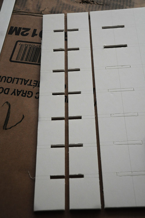
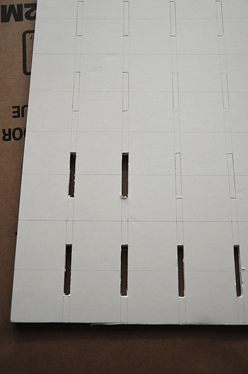
The first step was measuring and drawing out the cutting lines on the board in pencil. After my previous adventures in RGB LED Testing, I’d settled on an inside dimension of 2×2″ for each cell. Since the matrix is composed of 8×8 cells, I needed to cut 14 identical grid pieces. I tried to take a photo of the entire sheet after drawing in all the guide lines, but the lines didn’t show up clearly. Below is a close-up instead:

I found that it’s easiest to lay out the cuts so that the grooves on each adjacent pair of grid pieces are facing each other. This way, you can cut 2 slots at once. I first cut the slots, and then I cut out the grids:

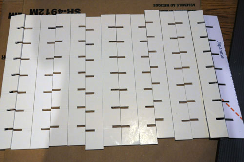
Note that you need to use extremely sharp blades when cutting foam-core poster board. Once your blade begins to dull, it won’t cut through the foam smoothly, and instead, it makes it turn into nasty little chunks as the blade drags through. If your blade starts to dull, change to a new one. Also, make sure to avoid putting excessive pressure on the board with your elbows, knees, etc … once the foam compresses, it won’t bounce back. I spent about 5 hours total cutting out the 14 pieces below:

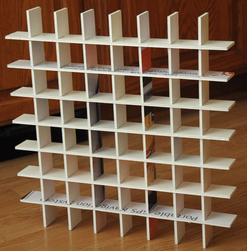
It was a tedious and boring task. Lucky I had a TV set in the room. When it was done, my arms, fingers, and back were all so sore, I had to pop 400mg of ibuprofen! Below are the fruits of my labor:

I bought a can of white gloss spray paint to paint over all of the printed bits, so unlike the photo above, the final product looks entirely white. In retrospect, I’m not sure it was worth using recycled board, because of the labor and cost of the paint. I’m not 100% sure that it was really necessary to paint it white – maybe the dark bits wouldn’t cause reduced brightness – but I didn’t want to take a risk … it would be hard to paint after wiring up the LED’s.

The next step is wiring up the 64 RGB LED’s … 4-wires each means a total of … 256 wires – 512 connections! Another long and grueling task!

Related articles:


Colorduino ICSP At Last

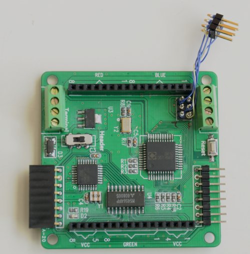
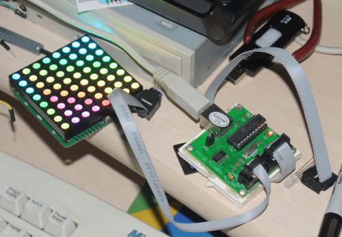
I’ve been pondering how to use my USBtinyISP to program my Colorduino ever since I got it. The problem with the beta board is that the ICSP header is positioned so close to the adjacent connectors that it’s impossible to plug a cable into it. I tried using header extensions to raise it up, but then the matrix had to be removed when programming the board. I didn’t want to do a messy soldering job that would be hard to undo. Finally, I settled on using wire wrap to attach another header. The beauty of wire wrapping is that it’s easy to undo. Here’s what it looks like:

Note that it’s safer to route it through the top, rather than to the right, because it’s too easy to short it against the male header on the right side. After I took the photo, I also potted the bottom pins of the dangling header with hot melt glue to further protect from shorts. Here’s my USBtinyISP connected to it:

What’s convenient about using ICSP to program the Colorduino is that I’m working on a Processing sketch to communicate with it via the serial port from my PC. Since the serial port is no longer shared between the Arduino IDE and my Processing sketch, it’s a lot faster to work on both the Processing and Arduino sketches simultaneously.

Colorduino Library for Arduino

I wrote a Colorduino library for Arduino.  It handles initialization and double-buffered drawing on ITead Studio’s Colorduino.  It is also compatible with Itead’s Arduino RGB Matrix driver shield. Included with the library is a sample sketch to show how to use it, ColorduinoPlasma, which draws a pretty plasma on an 8×8 RGB matrix.

To install the library, download the zip file (see below), and copy libraries/Colorduino to your arduino sketchbook/libraries/Colorduino. If you are already running the Arduino IDE, you must restart it before you can use the library. You can then run load ColorduinoPlasma.pde demo.

To include the Colorduino library in your own sketch, just

#include <Colorduino.h>

Then your setup() function needs to just call two functions for initialization:

void setup()
{
Colorduino.Init();
// compensate for relative intensity differences in R/G/B brightness
// array of 6-bit base values for RGB (0~63)
// whiteBalVal[0]=red
// whiteBalVal[1]=green
// whiteBalVal[2]=blue
unsigned char whiteBalVal[3] = {36,63,63}; // for LEDSEE 6x6cm round matrix
Colorduino.SetWhiteBal(whiteBalVal);
}

Colorduino.SetWhiteBal() is used to adjust the white balance. You can put

ColorFill(255,255,255);

in your sketch to test the white balance by drawing a white screen.  Then adjust whiteBalVal until your screen approximates white.

The origin of the screen, (0,0) is at the bottom left corner. The off screen buffer can be accessed either pixel by pixel:

Colorduino.SetPixel(x,y,r,g,b);

or by direct manipulation.  The screen buffer is arranged by row. For instance to set all of the pixels in the second row to the same color:

PixelRGB *p = GetPixel(0,1);
for (int x=0;x < ColorduinoScreenWidth;x++) {
p->r = red;
p->g = green;
p->b = blue;
p++;
}

After you finish updating your screen, make it live by swapping it with the currently display buffer:

Colorduino.FlipPage();

The latest version of the Colorduino library can always be downloaded from github: https://github.com/lincomatic/Colorduino/archive/master.zip

ITead Studio Colorduino – A Preview

ITead Studio kindly sent me a Colorduino for beta testing. The Colorduino was inspired by SeeedStudio’s Rainbowduino LED Driver Platform. Its form factor is very similar to that of the Rainbowduino, and the layout of the connectors was intentionally designed to mimic the latter. Both boards are based on the ATmega368 MCU, and are Arduino compatible. The principal difference between the platforms is that while the Rainbowduino is based on 3 MBI5168 constant current sink drivers and a M54564 darlington source driver, the Colorduino pairs the M54564 with a single DM163 constant current driver. By using the DM163, the Colorduino gains three 8+6-bit channels of hardware PWM control of the LED’s freeing up the MCU from having to implement it in software. This gives the ATmega more CPU bandwidth for performing other tasks. In contrast, the Rainbowduino implements three 4-bit channels of software PWM. One important limitation, however, is that the DM163 only has 24 channels… this is just enough to buffer one line of 8 RGB LED’s (8×3 = 24), rather than an entire 8×8 RGB matrix. So while the MCU is freed of the software PWM task, it still has to constantly scan line by line to refresh the screen. However, the row scanning takes up considerably less CPU bandwidth than having to also handle software PWM, and ups the bit resolution of each color channel to 8+6 bits.

The extra 6 bits of data in each color channel allows software control of the relative PWM brightness, so that the user may not have to resort to using external resistors to adjust relative channel current (which is also supported by the DM163, but the Colorduino, unlike the Rainbowduino, does not have onboard potentiometers for adjusting individual RGB current).   The Colorduino is quite compact (the same size as the Rainbowduino), being slightly smaller than the 60x60mm common anode RGB LED for which it is designed as a direct plug-in.

The Colorduino is pictured below:
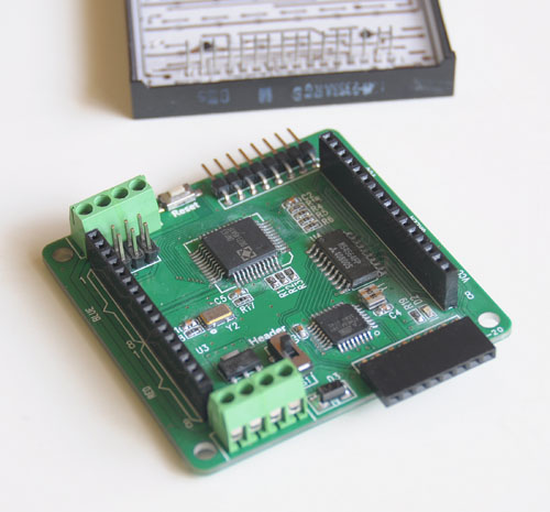
Behind the Colorduino is my LEDSEE 60x60mm RGB matrix.

Below is a top view:

Keep in mind that this is a beta board, and ITead is still tweaking it.  One problem I found is that the ICSP header doesn’t have enough clearance for me to plug in my USBtinyISP.  The sliding switch is for selecting betwen onboard regulator (for use with 7-12V power supplies) or a regulated 5V input.  As you can see, the board is a bit rough looking, with crooked parts and flux residue.  ITead Studio has assured me that the ICSP header will be moved to a better location, and that the production boards will be cleaner.  Also, although the beta boards have an ATmega168, the production boards will use the ATmega368.  Note the 8-pin headers for easy daisy chaining.  When multiple boards are snapped together, a host can address each one individually via I2C.  The power is also easily interconnected between the boards via the dual 4-pin green screw terminals.  Bottom view below, snapped into the 8×8 RGB matrix:

From the photo above, you can see how compactness of the Colorduino.   It’s slightly smaller than the RGB matrix.  NOTE: The bypass cap yellow added between VDD and GND will be moved to the PCB before production.  One downside of the Colorduino (which is shared by the Rainbowduino), is the dearth of I/O pins left over for the user.  TX/RX/SCL/SDA are all you have to play with, and some or all of them may needed for communication.  If you need more I/O, a likely scenario will be to connect the Colorduino to an Arduino via I2C.  Kind of a shame, given that the hardware PWM frees up considerable CPU bandwidth for other functions.

Below is the Colorduino running a plasma demo.  Notice my Arduino Duemilanove attached on the left, supplying power.  Since I can’t use ICSP, I’m using the Duemilanove, which you can see on the left, as a serial programmer.  I would like to get my USBtinyISP connected, so I regain some of the ATmega168’s small memory space by getting rid of the bootloader.
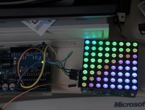
Finally, below is a rather horrible video of it running ITead’s demo code, followed by my plasma demo.  There is absolutely no flicker when viewed with the naked eye, what you see in the video is just an artifact.


The photos and video don’t do it justice.  The Colorduino supplies considerable drive current, making the matrix blindingly bright.  The LEDSEE 8×8 matrix is gorgeous.  I wish I could capture it properly in my photos.  I chose it because it was cheaper than the alternatives I found, while having the brightest output.  However, it took 2 weeks for LEDSEE to ship it out, and in total, it took over a month for me to receive it.  I sent them several inquiries about my order, which they completely ignored.   In light of their bad (nonexistent) customer service, I doubt I will deal with LEDSEE again.  ITead, on the other hand, has been quite responsive in their communications.

Currently, the Colorduino documentation is rather sparse.  ITead has a blog entry where you can download the schematic, DM163 spec, and their sample Arduino sketch.  ITead anticipates that the revisions will be completed and it will be put into their iStore sometime in April.  They are targeting a price of about $27, slightly higher than the Rainbowduino.  ITead Studio also makes an
Arduino RGB LED Matrix driver shield, which is already available for $14.80. When this shield is plugged into an Arduino Uno/Duemilanove, the combination is equivalent to a Colorduino, and uses exactly the same code.

Upon initial testing, the Colorduino appears to be a worthy challenger to the more established Rainbowduino, which has already spawned a dedicated ecosystem of  hackers, as well as a wiki full of detailed information. While the Colorduino has a lot of catching up to do, it seems quite capable, I look forward to running it through its paces in the coming weeks, when I use it to implement a large scale 8×8 RGB matrix.

You can download my plasma sketch, along with my interface library here: Colorduino Library for Arduino
RGB LED Testing

I bought 100 diffused 5mm RGB LED’s on eBay for my upcoming project, an 8×8 RGB matrix. I was extremely impressed by the fast (free) shipping – 7 days, all the way from China! Much to my chagrin, when I started testing them, I found that the vendor had sent me common cathode, rather than the common anode LED’s that I had been expecting. This is a big setback for me, because I was going to use them with the Colorduino that ITead Studio is graciously sending me for beta testing. The Colorduino expects common anode LED’s, so now I have a pile of 100 useless LED’s. Nevertheless, I decided to test them out to find out their brightness, color mixing, and diffusion characteristics.

Andy Rapp has posted a handy setup for testing RGB LED’s on his blog. He wrote a Java program and Arduino sketch, which allows you to interactively control an RGB LED with a host PC. I downloaded his code, and had it running very quickly.

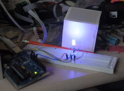
I also built a little 2x2x2 foam box, and put a piece of Grafix .005″ thick matte drafting film on top of it. The LED works fairly well. I’m satisfied with how well the combination diffuses the light.

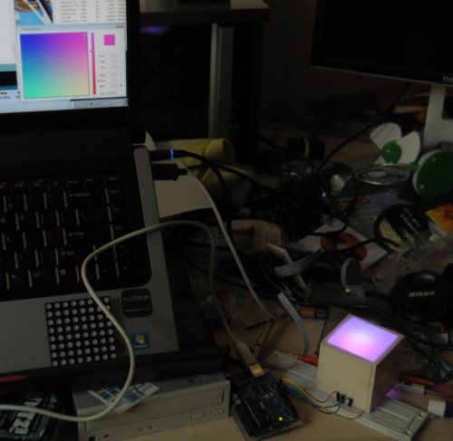
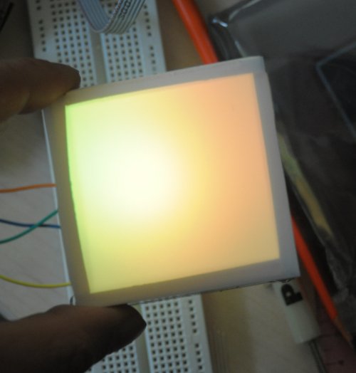
Andy’s Java app puts up a color picker on the host computer screen, which lets you interactively test out different colors in realtime. You can see the color picker in the bottom right corner of my computer screen. The brightness of a single LED is better than I was expecting, but the color mixing is not. It’s hard to see in the photos, but the red/green/blue components don’t mix that well, and the individual colors are brighter in certain areas.   In the photo above, notice how one side of the box is more purple, and the other side is more magenta.  This makes it impossible to get a decent approximation of white, even when you compensate for the fact that the 3 colors differ quite a bit in brightness when the same current is passed through them.  Below are some more shots.  In the yellow shot, I’m raising the box up so that the LED is lined up with the bottom of the box.  This makes the light noticeably smoother looking.   Note how the light is not centered in the box, even though I have the LED pointing perfectly vertical.  I may have to make minor adjustments when I build the real matrix.

It looks bright enough that I may be able to get away with just using 1 LED per cell.  I’ll have to see when I get the correct common anode LED’s and the Colorduino to play with.

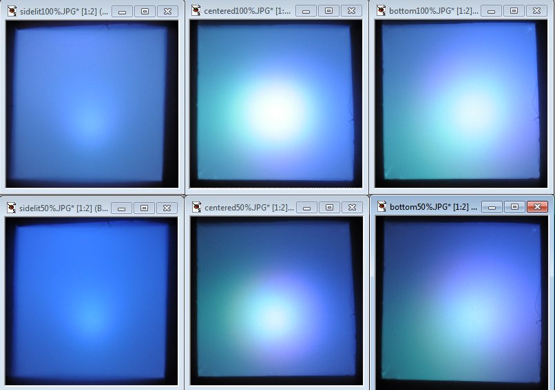
UPDATE: I did some more testing.  In the photo below, the top row is @ 100% brightness, and the bottom row is @ 50% brightness.  In the left column (“sidelit”), the LED is centered in the box, but pointing to one of the walls (so the view of the LED through the hole is the side of the LED).  In the center column (“centered”), the LED is pointing straight at the  and is physically centered in the box.  In the right column (bottom), the LED is pointing straight at the drafting film, but aligned w/ the bottom of the box.  As you can see, the “sidelit” setup has the best color mixing and is the most even in brightness.  The “centered” setup is brightest, but has the biggest hot spot, and the colors don’t mix as well.  The “bottom” setup is a bit more even in brightness, but still suffers from uneven color mixing.  I’m still undecided about which way to go.  What I like about the “sidelit” setup is that it enables the option of making a free-standing matrix that lights up two sides instead of just one.  I guess I’ll have to put off the decision making until I get the Colorduino and the common anode LED’s.  I contacted the eBay vendor this afternoon, and he says he’ll rush out the common anode LED’s tomorrow.  Hopefully, they will arrive in a week.

Comparison of LED placements - click to see full size

How to Use the Arduino IDE with an External Programmer

If you have a hardware AVR programmer, such as the USBtinyISP, you can configure your Arduino IDE to use it for uploading sketches, rather than the standard USB interface.  Why would you want to do this?

  1. it uploads faster
  2. your project will boot faster
  3. you can load bigger sketches, because you don’t need the bootloader anymore.
  4. it’s a lot more convenient when debugging communications between a host computer and the Arduino’s serial port, because you don’t have to share the port with the Arduino IDE and take turns accessing it.
  5. you want to build a project which uses the Rx/Tx pins on the MCU, which conflicts with programming via serial.
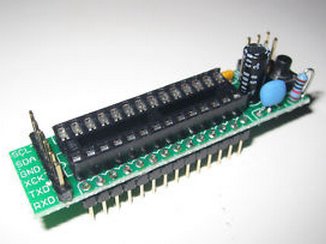
  6. you can use it to program stripped down AVR boards, such as the $2.99 board pictured below:


Windows users only: First, you must install the device driver. Follow the instructions here: http://www.ladyada.net/make/usbtinyisp/drivers.html


First, open your Arduino/hardware/arduino/boards.txt file in a text editor, and add the following lines:

##############################################################

usbtiny328.name=[usbtinyisp]ATmega328

usbtiny328.upload.using=usbtinyisp
usbtiny328.upload.maximum_size=32768

usbtiny328.build.mcu=atmega328p
usbtiny328.build.f_cpu=16000000L
usbtiny328.build.core=arduino
usbtiny328.build.variant=standard

Note:  The …variant=standard line is only needed for Arduino 1.0+. Older versions of Arduino will just ignore it.

If you’re using a programmer other than a USBtinyISP, substitute its identifier where I’ve typed usbtinyisp above. You can see the options in your hardware/arduino/programmers.txt file. In arduino-0022, the options are avrisp, avrispmkii, usbtinyisp, and parallel (beware, it’s case sensitive, so for instance, you must type usbtinyisp, not USBtinyISP). To support a different MCU, substitute it in the usbtiny328.build.mcu= line, e.g. atmega168. If you want to support more than one programmer/MCU combination, just add multiple sections with the different configurations to your boards.txt file.

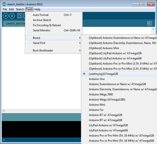
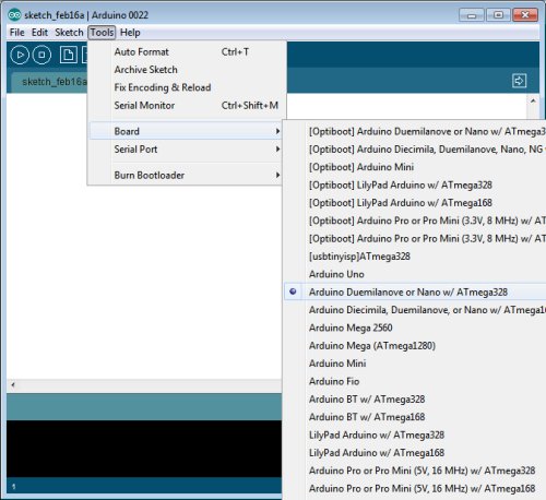
Next, hook up your programmer to the ICSP header on your board, and plug it into your computer. Select your new board configuration from the arduino Tools->Board menu:

Now, you can burn your sketch as usual, via the Upload button. Note that your bootloader will be overwritten, so you won’t be able to burn sketches to the same board without your programmer, unless you follow my instructions for restoring the bootloader below. On the other hand, after configuring your arduino software as described above, you can still burn sketches to arduinos which have the bootloader installed without your programmer. Simply pick the correct board from the Tools->Board menu.

———————————————————
Restoring the Bootloader

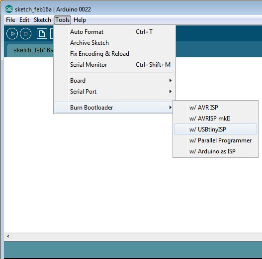
Once you’ve burned a sketch to an arduino via ICSP, the bootloader will be overwritten. If you want to revert to burning your sketch without a programmer, you must first restore the bootloader. With your programmer connected via ICSP, select Tools->Burn Bootloader:

Now, you can disconnect your programmer and hook your arduino directly to the computer via USB. From the Tools->Board menu, select your board:

Now, things are back to normal, and you can burn your sketch via the Upload button.

Build Your Own Daft Punk Table (5×5 LED Display)

Welcome my blog. This is my first post.

This is a 5×5 LED matrix display I built, using an ATmega368 microcontroller (arduino) and 25 warm white LED’s.  It was inspired by the Daft Punk coffee table, which is no longer sold.

I posted my first Instructable last Sunday.  It got selected by the editors to be Featured, which won me a free 3-month Pro membership.  I entered it into the Sparkfun Microcontroller Contest.  Today is the last day of voting.

http://www.instructables.com/id/Yet-Another-Daft-Punk-Coffee-TableDisplay/

I will be revising it and adding features, such as live music synchronization. I will post the developments on this blog as they happen, with detailed instructions.