Teensy 3.0 – First Look

I recently backed Paul Stoffregen’s Teensy 3.0 on Kickstarter.  Paul is a contributor to the Arduino project, and is the creator of the Teensy line of AVR-based Arduino compatible boards.  Of all of the projects on Kickstarter that I have backed, the Teensy 3.0 was the by far the fastest to ship after the close of funding.

Teensy 3.0 is not currently listed on the PRJC website, as Paul is working on first fulfilling all of his Kickstarter pledges.  However, if you are lucky, you might be able to score one via this hidden URL: http://www.pjrc.com/store/teensy3.html.

Unlike the its 8-bit brethren, Teensy 3.0 is based on a 32-bit ARM Cortex-M4 MCU, specifically, Freescale’s “Kinetis” K-series PK20DX128VLH5 (first batch, subsequent batches will be the functionally equivalent MK20DX128VLH5).

Here are Teensy 3.0′ technical specs:

  • 32 bit ARM Cortex-M4 48 MHz CPU (M4 = DSP extensions)
  • 128K Flash Memory, 16K RAM, 2K EEPROM
  • 14* High Resolution Analog Inputs (13 bits usable, 16 bit hardware)
  • 34* Digital I/O Pins (10 shared with analog)
  • 10 PWM outputs
  • 8 Timers for intervals/delays, separate from PWM
  • USB with dedicated DMA memory transfers
  • 3 UARTs (serial ports)
  • SPI, I2C, I2S, IR modulator
  • I2S (for high quality audio interface)
  • Real Time Clock (with user-added 32.768 crystal and battery)
  • 4 general purpose DMA channels (separate from USB)
  • Touch Sensor Inputs

All pins have interrupt capability.

* 14 Digital-only and 10 Analog/Digital pins are accessible around the exterior of Teensy 3.0, and available when used on a breadboard.  10 more Digital-only pins, and 4 more Analog-only pins are accessible at interior and bottom-side pads.

Note that that unlike Arduino, the I/O pins operate at 3.3V. This makes level-shifting a requirement if you want to interface to your existing 5V Arduino peripherals.  On the other hand, 3.3V makes it ideal as a real-time I/O expander for the Raspberry Pi.

Like its other Teensy brethren, USB device support is built in.  Software support for USB host mode is slated to be available in 2013.

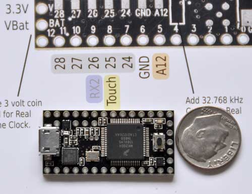
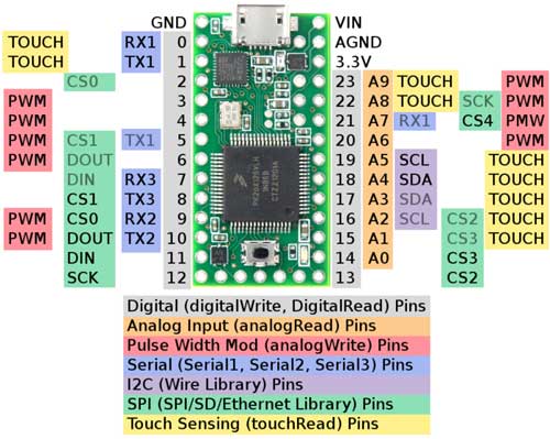
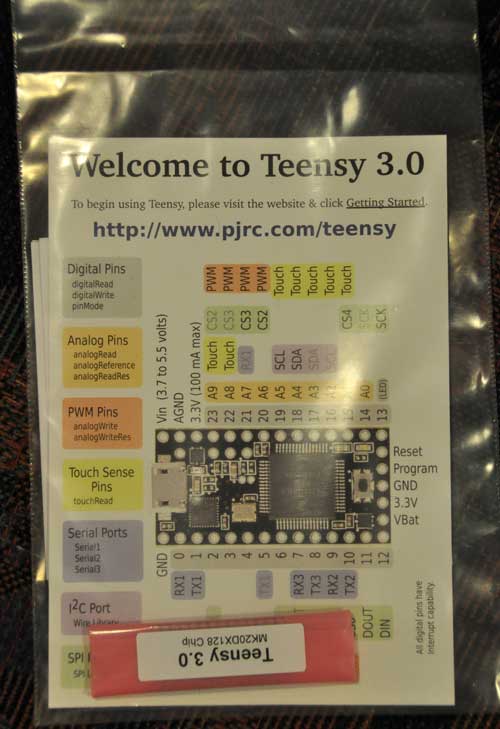
My Teensy 3.0 arrived in a padded envelope via USPS.  It came packaged with a handy pinout reference card, which shows the pinouts and their usages on both the top and bottom of the board.

I knew the reason that it was named Teensy, but didn’t hit me exactly how teensy it was until I unpackaged it:

As of this writing, the the software is in its 5th beta, and is distributed as a pre-configured Arduino 1.0.1 distribution.  The download links are listed in Kickstarter Update #18: Fifth Software Update.  After launching the Arduino IDE, select Tools->Board->Teensy 3.0.  Once  Teensy 3.0 isselected, an interesting menu becomes available at Tools->CPU Speed.  The default setting is overclocked at 96MHz, which PRJC claims will run stably.  You can also select 48 or 24 MHz.

The board is pre-loaded with the standard Arduino LED blink sketch.  All I have tested so far is to verify that I am able to compile and upload the Blink sketch.  Note that in Files->Examples->Teensy, there are a many of standard Teensy example sketches, but I’m not sure how many of them are currently working with the Teensy 3.0.  The File->Examples->Teensy->Tutorial1->Blink sketch has the LED pin set to 11.  In order to blink the onboard LED on the Teensy 3.0, you must change the pin number back to the standard Arduino pin 13.  Like previous Teensy boards, the IDE launches Teensy loader to do the actual transfer to the board, rather than using avrdude.

Normally, it is not necessary to press the button on the board in order to initiate firmware upload, but it is there as a backup. Firmware upload is very fast, since the Teensy 3.0 has a native USB interface, rather than going through an FTDI Serial->USB converter.

I am looking forward to building projects with the Teensy 3.0, once I figure out a use for its extra horsepower.
AT90CAN Support for Arduino 1.0+

I have adapted the Arduino AT90CANxx support to work with Arduino 1.0+. Also, I have moved the code to github, so that it will be easier to update.  Note that the Arduino 1.0+ support is currently only alpha quality.  I have compiled a few sketches, but I also have found some which currently can’t compile.

You can always download the latest version at https://github.com/lincomatic/AT90CAN

It is easiest to download the whole repository as a zip file: https://github.com/lincomatic/AT90CAN/zipball/master

Follow the instructions in the README file.  For more information, see the post linked below.

Related Post: AVR CAN Bus Project – Step 1: Programming AT90CAN128 with Arduino

OpenSprinkler – An Open-source Internet-connected Sprinkler Controller with Web Interface

My house has a crazy amount of sprinklers.  In the front yard alone, there are 14 channels, which have been controlled by two very old Irri-Trol DewBee 7-channel units. I’m sure that they were fancy high-end stuff when they were purchased, but they look like they’re over 20 years old.  Not only were they a pain in the ass to program, but for the past year, they’ve been flaky, watering on the wrong days.  Another irritant is that they use a 9v battery backup which doesn’t last very long, so every time we have a long power outage, I’ve had to spend 1/2 hour reprogramming them.  It was high time for a replacement, but I couldn’t find anything that met my all of requirements at the hardware store:

  • easy to program
  • supports 14 channels
  • non-volatile program storage, so no reprogramming needed after long power outages
  • automatic clock setting after power outage
  • inexpensive

In addition, I thought it would be cool to be able to control it from the Internet, so I could change the settings if necessary, when away from the house.  I recently started playing with my Raspberry Pi, and was looking for a project to do with it, as a way to learn the ropes.  An Internet-connected sprinkler with a web browser interface immediately came to mind.  The RPi seemed perfect for the task, with its built in Internet connectivity, SD card, and tons of RAM.  One thing I’ve found with Arduino is that it’s easy to run low on memory when implementing web interfaces on it. No such problem with the RPi.  The RPi doesn’t have enough GPIO pins to handle my 14 channels + an LCD display, but I figured that I could cook something up with I2C.  The control aspect seemed  relatively easy to handle, but then I started thinking about how much work the web interface would entail.

Before starting on my own DIY sprinkler, I decided to search for existing open source sprinklers and happened upon Ray’s Hobby’s OpenSprinkler.  As soon as I saw it, I knew that I shouldn’t bother reinventing the wheel.  OpenSprinkler is an Arduino-compatible system with:

  • open source hardware and Arduino-compatible firmware
  • ATMega 328 MCU, 16×2 monochrome LCD, Ethernet, and onboard USBtinyISP
  • web-browser-based interface + direct HTTP interface for writing your own scripts
  • 8 channels, extensible in increments of 8 channels with extension boards
  • completely solid state, using 8 triacs instead of relays

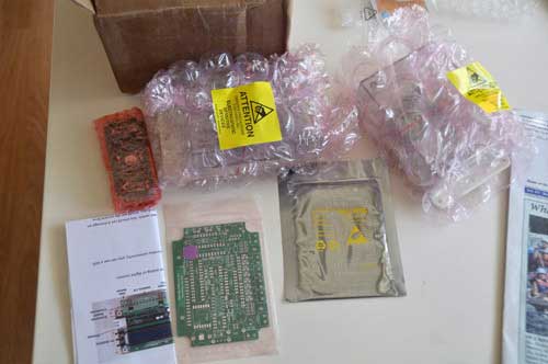
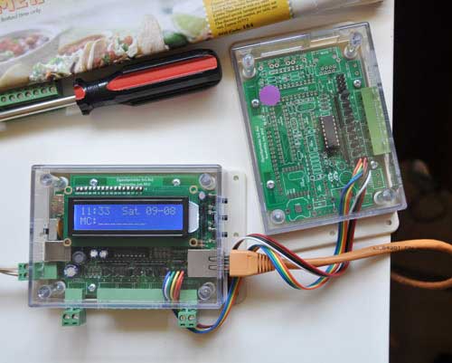
Since I needed 14 channels, I ordered a DIY OpenSprinkler 1.4u kit ($89.99) and an extension board ($25.99).  Pre-assembled SMT boards are also available at higher cost. Shipping was very fast, and I received a box a few days after I placed the order.  The kit came nicely packaged, with bubble wrap protecting all of the delicate parts:

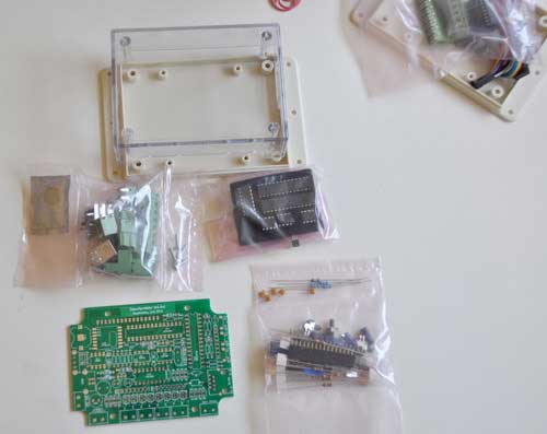
The components were also bagged in separate groups, which made finding the parts easier:

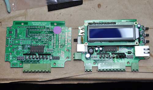
Ray’s Hobby has great documentation on their website.  The step-by-step assembly instructions are very clearly written, with lots of photos, and easy enough for even a noob to follow.  It took me about 3.5 hours to assemble both the main board and extension board, and one hour of that was spent undoing a careless error on my part.  I inadvertently soldered 4 of the triacs on the main controller board backwards, and had to clip the leads and solder them onto the top of the PCB in order to reverse the connections.  You can see in the photo below that the rightmost 4 triacs are all askew due to my messy rework:

The kit doesn’t come with a 24V transformer, so I salvaged one from one of my DewBees.  The firmware is completely open source Arduino code, and is hosted on github.  The controller has a built-in USBtinyISP, so you don’t need an FTDI cable or programmer to load the firmware.  It comes preloaded with the latest release, so I didn’t test uploading new firmware yet.

Ray takes the cautious approach, walking the user through inserting only the switching regulator and testing the power supply voltages before inserting the remaining IC’s.  After verifying the 5V and 3.3V supply voltages, I inserted the rest of the IC’s and to my delight, the unit powered up flawlessly on the first try:

The unit has a test mode that is entered by pressing and holding the top button while powering up.  In test mode, it cycles through the channels, turning each one on for 5 seconds.  I tested the triacs with a voltmeter, and was happy to find that I hadn’t fried any of them or messed up any PCB traces while doing my rework.

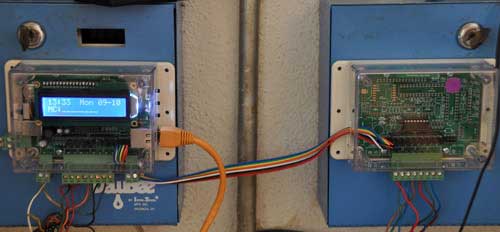
I mounted the units on top of my existing controllers by simply sticking them on with double-sided foam tape:

This way, I can revert to the old controllers when I sell my house.  I’m not sure if the new owners will be savvy enough to figure how to connect it up to the Internet, figure out the IP number mapping to the unit, and then pull it up on a web browser.

For Internet connectivity, I’m using an old Linksys WRT54G in running DD-WRT in wireless repeater bridge mode.  An added benefit is that I can now use my house’s WiFi from my driveway, where the signal was previously too weak.    I have my router set up to assign a fixed IP to the OpenSprinkler.  If you forget the IP number, pressing the 2nd button displays the current IP number and TCP port.

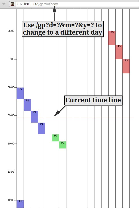
The web interface is a bit quirky, but it’s easy to use once you figure it out, and has  a terrific graphical preview screen.  The preview screen is actually one of the features that really sold me on OpenSprinkler, because it makes it very easy to check your programming for errors:

Ray cleverly gets around the limited memory of the ATMega328 MCU, and avoids having to have an onboard SD card by hosting a bunch of javascripts on his own webserver.  This means that in order for the web interface to function, the unit must have Internet connectivity.  You can host the scripts on your own LAN if you wish, but then you need to have a webserver running at all times.

I’ve only OpenSprinkler running for a couple of days, but so far, it’s running flawlessly.  I am very impressed with the quality of Ray’s Hobby’s products and detailed documentation, and would definitely recommend them to my friends.  Ray is actively working on improvements to the firmware, and since it’s open source, I’m able to hack it any way that I please.

Teensy 3.0

I just backed the Teensy 3.0 on Kickstarter.  It’s designed by Paul Stoffregen, the same wizard behind the Arduino-compatible Teensy boards.  It sports a 32-bit ARM Cortex-M4 chip, and is programmable via Arduino and C.  This looks like it’s going to be a great platform for building embedded projects that need more power than the typical Arduino.  The board is tiny compared to Raspberry Pi.

Technical Specs:

  • 32 bit ARM Cortex-M4 48 MHz CPU (M4 = DSP extensions)
  • 128K Flash Memory, 16K RAM, 2K EEPROM
  • 14* High Resolution Analog Inputs (13 bits usable, 16 bit hardware)
  • 34* Digital I/O Pins (10 shared with analog)
  • 10 PWM outputs
  • 8 Timers for intervals/delays, separate from PWM
  • USB with dedicated DMA memory transfers
  • 3 UARTs (serial ports)
  • SPI, I2C, I2S, IR modulator
  • I2S (for high quality audio interface)
  • Real Time Clock (with user-added 32.768 crystal and battery)
  • 4 general purpose DMA channels (separate from USB)
  • Touch Sensor Inputs

At $22, it’s a bargain.  The campaign ends on Sept 16, so get them while they’re hot!

Cheap 16×2 LCD Comparison

HD44780-compatible 16×2 LCD’s are cheap (<$4), and easy to use with Arduino via the LiquidCrystal library. To reduce the pin count considerably, the Adafruit LCD backpack is a nice little add-on that converts them to work via a two-wire I2C or SPI interface.

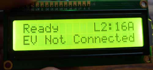
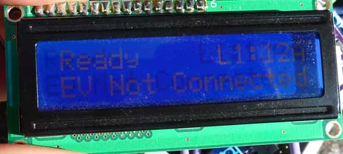
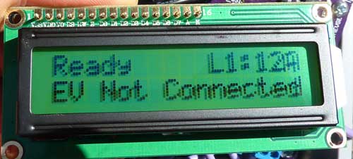
I bought two types to compare for use with OpenEVSE and LeafCAN. One has white lettering over a blue background, and the other one has black lettering over a yellow background. Here is an indoor comparison:

My camera can’t take good photos of the blue LCD indoors. The blue background is actually a good bit darker than in the photo, and the contrast is much better than it appears. Factoring that in, I guess I would still give the yellow LCD a slight edge indoors.

Now, here they are outdoors, in direct sunlight:

Again, the blue LCD didn’t photograph well. It looked slightly better than depicted in the photo. However, it’s a clear win for the yellow LCD. It works as a reflective LCD in direct sunlight, with very high contrast.

Colorduino Library v1.2.3 Released

Thanks to wiltwong and Markus Lange, I have added support for Arduino Mega and Leonardo to the Colorduino Library.  Markus also helped to clean up the code a bit for Arduino 1.x.  I have added the ColorFill() function to the ColorduinoObject class, as well, so you don’t have to copy it from ColorduinoPlasma.pde.

You can download it from github: https://github.com/lincomatic/Colorduino/downloads

AVR CAN Bus Project: LeafCAN v1.2 Released

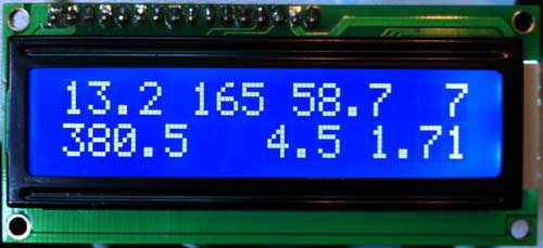
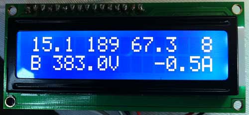
Another tweak today, I added instantaneous battery power consumption in KWh to the second line of the display. In order to make room, I had to do away with the V and A characters after the voltage and current draw. Here is the new display:

The top line, from left to right, contains Battery Pack Remaining KWh, SOC (“GIDs”), SOC % (GIDs/281*100), and Remaining Fuel Bars.
The bottom line now contains Battery Pack Voltage, Battery Pack Current Draw (Amps), and Battery Power Consumption (Pack Voltage * Pack Amps).

For users who prefer the old display, I added:

#define SHOW_KWH
#define SHOW_KW

If you comment out both lines, the display will be the same as v1.0, but with the smoothing that was added in v1.1.

As usual can download the latest release from github: https://github.com/lincomatic/LeafCAN/downloads.

Previous: AVR CAN Bus Project: LeafCAN v1.1 Released

AVR CAN Bus Project: LeafCAN v1.1 Released

I made some minor modifications to LeafCAN firmware today. First, I added display of remaining KWh in the battery pack, based on Phil Sadow’s formula of GIDs * 80 = Wh. Also, the display was a bit blurry when the values were updating rapidly, so I slowed down the refresh rate of the LCD to 250ms.

In order to make space for the KWh remaining value, I had to take out the % character in the SOC % display. Here is the new display:

The top line, from left to right, contains Battery Pack Remaining KWh, SOC (“GIDs”), SOC % (GIDs/281*100), and Remaining Fuel Bars.
The bottom line is unchanged, and contains Battery Pack Voltage, Battery Pack Current Draw (Amps).

You can download the latest release from github: https://github.com/lincomatic/LeafCAN/downloads. Note that I have added LeafCAN.hex, a precompiled file, for those who don’t have a working Arduino setup for compiling the code.

Previous: AVR CAN Bus Project: Step 4 – LeafCAN: Nissan Leaf SOC Meter
Next: AVR CAN Bus Project: LeafCAN v1.2 Released

How to Program an AT90USB1286/Teensylu/Printrboard with Arduino and USBtinyISP

My first step in loading Marlin RepRap firmware into the Printrboard is to get Arduino to play nicely with it.  The method I am going to describe in this article for programming a Printrboard with Arduino will work with the Teensylu or any other device that uses the AT90USB1286 and has an ICSP connector.   The programmer we are going to use is a USBtinyISP or compatible. Since the AT90USB1286 isn’t officially supported by Arduino, it takes a bit of setting up to get things working properly.

I first looked at the instructions on Teensylu’s page in the RepRap wiki, but found them very confusing, and I didn’t like the idea of having to send the HEX file to the MCU using an external utility instead of doing everything within the Arduino IDE. So, I set out to streamline the process and document it as I went.  If you follow my method below, you’ll be able to compile and download your firmware all within the Arduino IDE.

Step 1: Download and install Teensyduino

Teensyduino was created by PJRC for their Teensy line of boards.  Teensy is a great alternative to Arduino if you want an ultra compact board with built in USB.  The Teensy++ happens to also use the AT90USB1286, so it’s compatible w/ Printrboard/Teensylu.  Follow PJRC’s instructions for installation from the download link.

If you only plan to program for RepRap, you don’t need to install any of the libraries.  On Windows, you will be prompted to install the serial driver. Select yes.  You don’t have to worry when Windows complains that the driver is unsigned… it’s just an INF file to tell Windows to use one of its own built-in drivers.

Step 2: Modify Teensyduino Configuration for use with USBtinyISP

Download at90usb1286txt.zip.

Navigate to where your Arduino files are located.  On my computer, I have them in d:\arduino-0022.  We will call this <arduinofolder>.  Now, find the subfolder where the Teensyduino library was installed:

<arduinofolder>\hardware\teensy

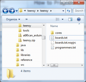
If you are in the correct folder, you should already see a boards.txt and a subfolder called core in there.  Drop the files from at90usb1286txt.zip into that folder, overwriting the existing boards.txt.  You should see something like this:

If you don’t plan to develop with any of PJRC’s Teensy or Teensy++ boards, you can keep them from showing up in your Arduino menu by copying boards.txt.nopjrc over boards.txt.

Now, when you start Arduino, you should see some new configurations in the Tools->Board menu.  The important ones are:

[usbtinyisp]AT90USB1286
[usbtinyisp]Teensylu/Printrboard
[BootloaderCDC]AT90USB1286
[BootloaderCDC]Teensylu/Printrboard

To use a USBtinyISP programmer, select either [usbtinyisp]AT90USB1286 or [usbtinyisp]Teensylu/Printrboard. The only difference between the two configurations is that I took the extra useless options out to make things simpler when programming Teensylu/Printrboard.  The Teensylu/Printrboard option is the same as the AT90USB1286 option with USB Type = Serial and CPU Speed = 16MHz.

At this point, you can plug in your USBtinyISP and into your AT90USB1286/Teensylu/Printrboard and start programming!

So what are the [BootloaderCDC] configurations for?  They allow you to download sketches into your target board directly through a USB connection to your host, without the USBtinyISP programmer.  See my next article for details on how to do that.

Update 20140909: I have uploaded a copy of Arduino 1.0.5-r2 for Windows to github, which is already modified to work with the AT90usb1286, so you don’t have to modify it as above. Simply go to https://github.com/lincomatic/arduino-1.0.5-r2-at90usb1286 and click the Download Zip button, and then extract the contents to your PC. My distribution also supports the USBasp in addition to the USBtinyISP.